Curtain control via RS-485 interface
About the benefits of curtain control via rs-485
Some time ago I had an electric curtain rod for AKKO AM72E sliding curtains. It's not that I am too lazy to move the curtains with my hands, but progress is moving forward and I am trying to mince next. The electric motor can be controlled by dry contacts and from the radio remote control. But who needs this commonplace, if the motor supports the RS485 interface, which allows not only to give commands, but also to read the state of the curtain. And in general, the ultimate goal is to manage the cornice from your phone, and why not.
The easiest way would be to find the USB-RS485 adapter and start testing. But there was no such adapter nearby. If ordered, would have to wait a while. Faster to do. I have several USB-UART adapters on all popular chips, but I mainly use a pair of adapters on CP2103. They look something like this:

Approximately, because the connectors are installed and additional signals are output. All you need to do is a UART-RS485 adapter. Several MAX485s were bought at the store. Perhaps it would be easier to use something like the MAX13487 with automatic transmission and reception shifting. But in a local store I did not find such (maybe I just looked badly). Honestly, I was too lazy to go to the store for the MAX485. At first, there was a desire to make reception on the op-amp, and the transmitter on transistors - it's just so easy to test whether the AM72E electric curtain works according to this protocol or not.
Back to Modern Electronics
It is up to the scheme. As a basis, I took the scheme from the journal "Modern Electronics" No. 1 for 2007. Everything looked rosy. The article says that “The GPIO pins of the CP2103 microcontroller are programmed as control outputs by default and correspond to their use in the USB-RS485 adapter circuit.” It turned out that this is not my case. I have adapters for a long time. The rare thing that fell into my hands is not subject to "improvement." Firmware in the adapters was not an exception, and even if they could have pushed RS485 as a girl, now these skills were completely bent off.
The evening ceased to be languid. Something was needed that would switch the MAX485 from transmit to receive. By the way, the adapter worked perfectly for transmission. In general, this could be enough, because there is nothing to read from the AM72E.
There were many options. The MAX485 on the board is mounted on a socket, and can easily be replaced by a microcircuit, with automatic transmission-reception switching. But this is not an option at all, because you have to go to the store. I also have adapters on the FT232, and these chips can switch the MAX485. Too easy. And I have already matured a plan, how can I have fun with the AM72E and for FT232 there was no place in it. It is necessary to supplement the scheme so that when the start bit appears on the TX UART, the MAX485 switches from reception to transmission and is in this state for the duration of the transmission of the entire byte, and then switches back to reception. Turning to my experience through google, I found out that this problem is being solved with the help of the NE555 timer. Indeed, why be smart. But I didn’t have any of the NE555 family timers. Then you know: the store is laziness.
One-shot for bummer ... not needed
You can make a single vibrator in a million ways. I even wanted to quickly remake the board and put the STM8S003 for these purposes. At first glance, this may look like a gun on sparrows, but if you compare the circuitry on the NE555 and STM8S003, the circuitry on the MK will be even simpler because only one capacitor is needed from the external elements. The program is literally a few lines in assembler. Everything is not bad with the price either - it is cheaper than the MAX485 in our store. There is one problem with the hardware timer (on the NE555). It will work perfectly at one speed. As soon as you need to change the exchange rate, you have to rebuild the timer. I often come across devices that, at startup, give out debugging information to the UART at one speed, and after loading go into exchange mode for another. And you never know why you may need to change the speed! At the same time, you won’t want to go into the circuit every time. Here the timer on STM8 can help - the program can be written so that the necessary timings are set on signal and do not require intervention. It is not very difficult. I don’t understand why I need to know something about the UART exchange rate. Many years ago, I came across UART devices that automatically determined the speed at which another device was connected and tuned to it on the fly.
I know that you would like to see a circuit without STM8S003. Okay, I'll meet you. And without this, I will be able to do something interesting out of a simple test. The scheme will not have a single vibrator at all:

I won’t explain what and how it works here - everything is standard and obvious. I can only say that I did not set jumpers near the resistors R5 and R7, that is, the circuit can be made simpler by removing all jumpers and these two resistors. The maximum you may need is R5. There are devices that, when answered, simply release the line when transmitting the last bits, if they are units. Then, without R5, the last byte may be distorted. In our case, this is not important since the last byte of the response checksum is transmitted. The circuit will work without R1, but we will need it later.
It looks like this for me:

Do not be discouraged if you do not see all the elements that are on the diagram. At first I made a circuit board according to the scheme from the article, and then I experimented with the receive-transmit switching circuit. The transistor (DTC143 in SOT23, immediately with the base resistor) and SMD resistors are soldered directly to the tracks on the back of the board.
If you put MAX13487, then nothing will remain of the circuit at all. Better yet, grab a standard USB-RS485 adapter. But then you will be tied with wires to the curtains. Stupid sight. Would I bother with the UART-RS485 adapter if I didn’t have an insidious plan?
Lua to help us
With iron on this finish. It is necessary to write a program. The program is only for the test. Nothing complicated. You need to send commands for AM72E to the serial port. Well, you can still read that he answers us there. For experiments, take a computer with Windows. We must choose the language in which we will write. The first thing that came to mind was powershell. No, I won’t torment you with powershell. Then python. Python is good for everyone - the code on it is portable to any OS, it’s clear, you can immediately screw the graphical interface, and for Windows you can also pack it as an executable so that few people understand that the program is in python. And still not python. There are many examples of working with a serial port on python, and without it there are many who wish to find it on their own. We will write the program on Lua. Yeah, a strange choice. Actually, I had no big choice. Either C or Lua. Why - more on that later. It’s possible in C. But no, not this time. Just because in C I write code so that after a couple of months I myself can’t understand it without taking substances that expand consciousness. Just kidding. So I write in any language.
Lua needs to be installed. We take from here: https://code.google.com/p/luaforwindows/downloads/list . It is installed in almost one click. A sufficient number of modules are included. There is everything you need. Including for the graphical interface - iup. If you decide that you need it - use it on health. But we will manage the command line. We are only for testing. And we need a module to work with the serial port. If we decided to test under Linux or Mac OS, then we could work with a serial port without an additional module - just like with a file. To access UART under Windows, we need the luars232 module. It is already in the assembly. Additionally, you do not need to search and install anything.
The file with the program - curtain.lua - is only a few dozen lines. If desired, you can still reduce. How to use, I will not explain. I will show the picture:
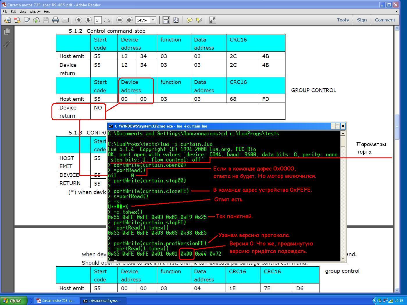
I will make only one explanation. This is already obvious, but if the line starts with the character ">", then this line is entered from the keyboard. If this character is not at the beginning of the line, then the line is received from the program.
I did not expect everyone to understand everything. The command line, like the wires, we do not need. Now all that matters is that the RS485 on the AM72E works great. No, I had a moment when I collected and checked everything, I started sending commands to AM72E, but he didn’t react at all. The thought that the RS485 still did not work flashed through my mind. But then I looked under the table, to where I have a power strip, and saw that the AM72E should also be connected to the network. After that, when sending the “Close” command, I heard a funny buzzing engine - everything works.
I’ll take a little rest and move on to implementing my “insidious plan” - I will teach my electric curtain rod to receive commands via WiFi. What I will report in the next article.









