Temperature control via SMS (Arduino Nano + Neoway M660)
In my opinion, SMS is a great way to turn something on / off from a distance.
Especially the heater.
Especially in the winter.
When you want it quickly to warm!
So, our characters:
As a GSM modem, the debug board of the Neoway M660 GSM module was used .

This is the path of least resistance, since you do not need to think about connecting an antenna and a SIM card, but it is inexpensive.

In general, the Neoway M660 is noteworthy in that it has few leads located at the edges (a “postage stamp” type case) at a great distance from each other, so for prototyping - that’s it.
The module is controlled by UART using AT commands ( description of AT commands of the M660 ).
Arduino Nano will be powered from a small 12 V power supply through the Vin pin.

After some thought, it was decided to power the GSM board from the Nano board via a USB connector.
The manual Neoway_M660_Module_Hardware_User_Guide says that if there is a capacitor with a capacity of 1000 μF in the power circuit, the current supply requirement is 0.6 A (at a voltage of 3.9 V).
On the M660 debug board and its USB tail, the total cost is 940 uF. The AMS1117 chip on the Arduino Nano board gives 5 V and 1 A output, the consumption of the Nano board with all the guts and the temperature sensor connected with Vin equal to 12V is about 24 mA. So we believe that everything is OK with the power circuit.
The Nano signal level is 5 V, the UART M660 interface is 2.8 V (voltage should not exceed 3.1 V). To coordinate the levels, we use the scheme from this article.
Pin 13 (lucky number!) Of the module - 2.8 V output (maximum current 5 mA), is specifically designed to power level matching devices. Just solder to pin 13 of the module, the other end to the level converter circuit.
To send SMS in text mode we need:
To receive SMS in text mode we need:
When a received SMS is sent to UART in text mode, it consists of two lines:
First we look at what number the message came from, then what exactly it came from. Conveniently.
To measure the temperature, an LM35 sensor was used. The sensor outputs a voltage proportional to degrees Celsius, 10mV / ºC. Simple and convenient. The sensor supply voltage is from 4 to 30 V.
If you include an internal 1.1 V reference source in Arduino (for this you need to set analogReference (INTERNAL); in setup (), then degrees Celsius can be calculated using a simple formula:
DEGREES Celsius = COUNTED VALUE x 0.107.
The read value is the one obtained from the analogRead () function:
val = analogRead (analogPin);
English-language reasoning on the topic of LM35 and Arduino: http://playground.arduino.cc/Main/LM35HigherResolution
At the beginning of testing, the temperature sensor was placed on long legs above the Arduino board and showed 28 - 29 ° С at an ambient temperature of 25 ° С. I already started to panic that I did something wrong, but as soon as the sensor was taken away from the board, the readings began to correspond to reality.
By the way, as it turned out, near the floor the air temperature is 1.5 - 2 degrees lower than on the table.
When unfolded, it all looks something like this:

In a simple version, you can send SMS commands to turn on / off the heating, receive reports on the status of the heater (on / off) and the measured temperature.
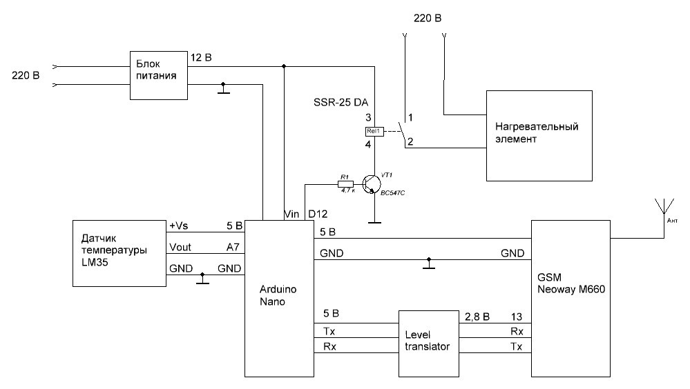
By the way, although the relay says that it starts to work when the voltage at the input is 3V, it didn’t work reliably from five volts (it might not work right away, turn off and turn on again). Therefore, the relay power was redone from an input source of 12V - in this case, there were no problems.
Especially the heater.
Especially in the winter.
When you want it quickly to warm!
So, our characters:
- Arduino Nano Board
- debug board with GSM module Neoway M660
- temperature sensor LM35
- power supply 12 v
- solid state relay
- wires, discrete components
As a GSM modem, the debug board of the Neoway M660 GSM module was used .
This is the path of least resistance, since you do not need to think about connecting an antenna and a SIM card, but it is inexpensive.
In general, the Neoway M660 is noteworthy in that it has few leads located at the edges (a “postage stamp” type case) at a great distance from each other, so for prototyping - that’s it.
The module is controlled by UART using AT commands ( description of AT commands of the M660 ).
Power Arduino Nano
Arduino Nano will be powered from a small 12 V power supply through the Vin pin.
GSM module power
After some thought, it was decided to power the GSM board from the Nano board via a USB connector.
The manual Neoway_M660_Module_Hardware_User_Guide says that if there is a capacitor with a capacity of 1000 μF in the power circuit, the current supply requirement is 0.6 A (at a voltage of 3.9 V).
On the M660 debug board and its USB tail, the total cost is 940 uF. The AMS1117 chip on the Arduino Nano board gives 5 V and 1 A output, the consumption of the Nano board with all the guts and the temperature sensor connected with Vin equal to 12V is about 24 mA. So we believe that everything is OK with the power circuit.
UART Level Matching
The Nano signal level is 5 V, the UART M660 interface is 2.8 V (voltage should not exceed 3.1 V). To coordinate the levels, we use the scheme from this article.
Pin 13 (lucky number!) Of the module - 2.8 V output (maximum current 5 mA), is specifically designed to power level matching devices. Just solder to pin 13 of the module, the other end to the level converter circuit.
SMS sending
To send SMS in text mode we need:
- AT + CMGS = \ "80123456789 \" \ r - enter a command with a phone number (80123456789 in this example).
- After that, the module should prompt “>” to enter the SMS text, which we should do.
- Text input must end with byte 0x1A.
- Neoway M660 replies OK - message sent !!!
Receive SMS
To receive SMS in text mode we need:
- AT + CMGF = 1 \ r - enable text mode if in doubt that it is enabled.
- Decide whether we need to save SMS on the SIM card or in the module’s memory, or just send them to UART. There is an AT + CNMI command for this. Since we did not want to save SMS in memory, we used this command with the following parameters: AT + CNMI = 3,2,2,0,1 \ r
When a received SMS is sent to UART in text mode, it consists of two lines:
- + CMT: "70123456789" \ r \ n - the first line contains the sender's number
- Text of the message \ r \ n - in the second - the text of the message.
First we look at what number the message came from, then what exactly it came from. Conveniently.
Temperature measurement
To measure the temperature, an LM35 sensor was used. The sensor outputs a voltage proportional to degrees Celsius, 10mV / ºC. Simple and convenient. The sensor supply voltage is from 4 to 30 V.
If you include an internal 1.1 V reference source in Arduino (for this you need to set analogReference (INTERNAL); in setup (), then degrees Celsius can be calculated using a simple formula:
DEGREES Celsius = COUNTED VALUE x 0.107.
The read value is the one obtained from the analogRead () function:
val = analogRead (analogPin);
English-language reasoning on the topic of LM35 and Arduino: http://playground.arduino.cc/Main/LM35HigherResolution
At the beginning of testing, the temperature sensor was placed on long legs above the Arduino board and showed 28 - 29 ° С at an ambient temperature of 25 ° С. I already started to panic that I did something wrong, but as soon as the sensor was taken away from the board, the readings began to correspond to reality.
By the way, as it turned out, near the floor the air temperature is 1.5 - 2 degrees lower than on the table.
What does it look like
When unfolded, it all looks something like this:
In a simple version, you can send SMS commands to turn on / off the heating, receive reports on the status of the heater (on / off) and the measured temperature.
By the way, although the relay says that it starts to work when the voltage at the input is 3V, it didn’t work reliably from five volts (it might not work right away, turn off and turn on again). Therefore, the relay power was redone from an input source of 12V - in this case, there were no problems.
What else can be done?
- you can program, for example, sending messages when there is an abnormal increase or decrease in temperature or a suspicious rate of change
- you can connect via GPRS to some server that will store data on temperature changes over the past 20 years, build beautiful graphs and reveal hidden patterns
- finally, for village houses with wood-burning stoves, it is recommended to connect the device to a robot that throws firewood into the stove
- waiting for your options)