May 18, 2018 at 19:18
Inverse kinematics in two-dimensional space
- Transfer
Part 1. Mathematics

Introduction
We are so used to interacting with the world around us that we do not think about how difficult our arms and legs move. In the academic literature, the task of controlling a robot arm is called inverse kinematics. Kinematics means " movements ", and the concept of " inverse " is due to the fact that we usually do not control the hand itself. We control the “engines” turning each individual part. Inverse kinematics is the task of determining how to move these engines to move your hand to a specific point. And in its general form, this task is extremely difficult. So that you understand how difficult it is, you can recall games such as QWOP , GIRP, or evenLunar Lander , in which you choose not where to move, but which muscles (or accelerators) to drive.
The task of controlling mobile drives extends even to the field of robotics. You should not be surprised that for centuries mathematicians and engineers have been able to develop many solutions. Most 3D editors and game engines (including Unity) have toolkits that allow you to rig humanoid and beastlike creatures. For various schemes (robotic arms, tails, tentacles, wings, etc.), embedded solutions usually do not exist.
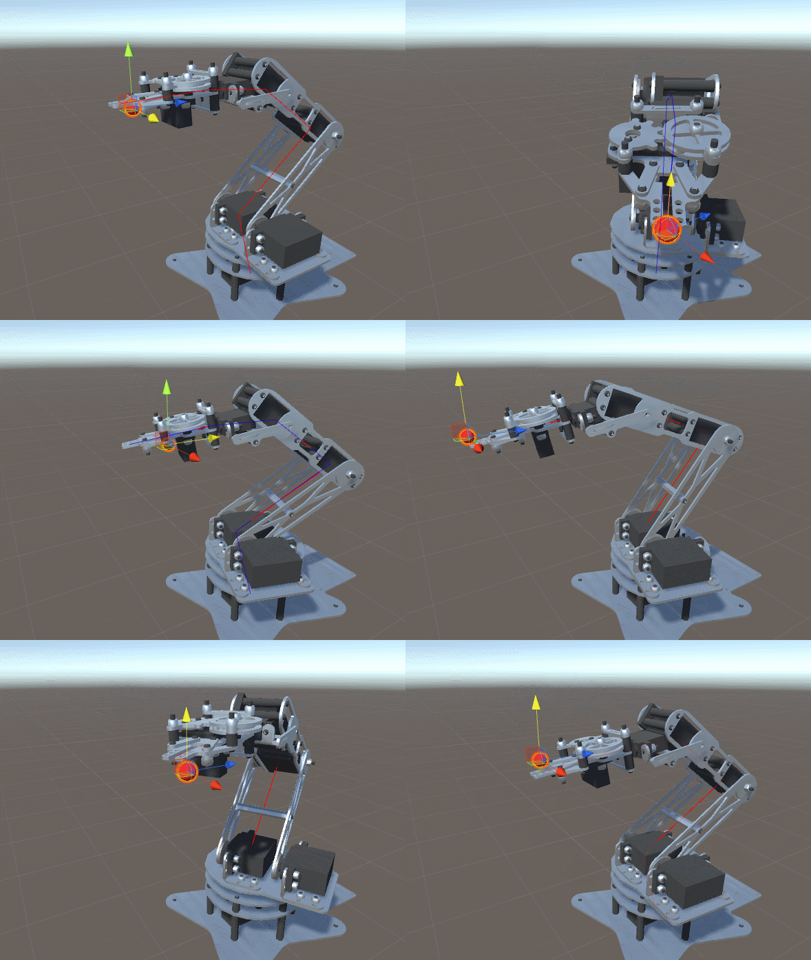
That is why in the previous series of articles on procedural animations and inverse kinematics, I proposed a very general and effective solution that can work with any scheme. But such power has its own compromise: efficiency. One of the most important reasons for criticizing my article was that the method turned out to be too long and costly while used for hundreds of characters. Therefore, I decided to write a new article on the inverse kinematics of the manipulator in two degrees of freedom. The technique described in this tutorial is extremely effective and can be used for dozens (if not hundreds!) Of characters at the same time.
Inverse kinematics
Let's imagine a robot arm with two segments and two hinges, similar to the diagram below. At the end of the manipulator there is a final link that we want to control. We have no direct control over the position of the final link and can only rotate the hinges. The task of inverse kinematics is to find the best way to rotate the joints to move the final link to the desired position.
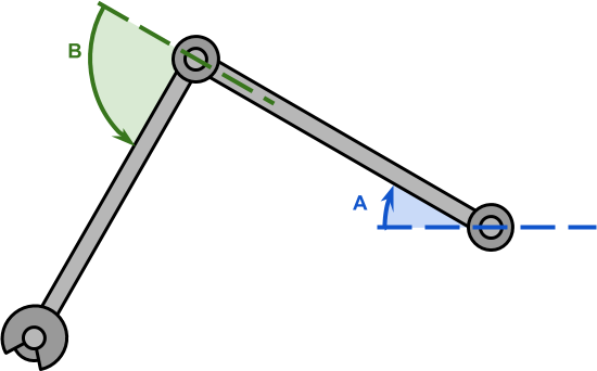
The solution proposed in this tutorial will only work for double-handed manipulators. In the academic literature, it is often written that such manipulators have two degrees of freedom . And the reason for this is perfectly clear from the diagram below. A robot manipulator with two degrees of freedom can be modeled as a triangle, which is one of the most well-studied figures in geometry.
Let's start by formalizing the task a bit. Two hinges
 and
and  (both are highlighted in black) can be rotated by corners (blue) and (green). This will force the end link to move to a position.
 .
.Inside corners
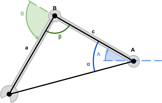
We can use three points
, and to build a triangle with internal angles  ,
,  and
and  as in the example below.
Although all three angles are unknown to us, we know the length of all the edges.
- Section
 denotes a hand and has a length
 ;
; - Section
 denotes the forearm and has a length
 ;
; - Section
 denotes the distance between the hinge of the shoulder and the brush, and has a length
 .
.
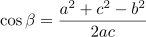
Knowing the three sides of the triangle is enough to find all three angles. This is possible thanks to the cosine theorem , which is a generalization of the Pythagorean theorem for triangles, which are not necessarily regular.
The two angles required to control the manipulator are and . Let's start with, which can be calculated using the cosine theorem:
We can transform the equation to transfer
 :
:
Now we need to apply the inverse cosine function
 (also known as arccosine ) to find:
Using the same procedure, we can again apply the cosine theorem to find
:
Derivation of the cosine theorem
Section divides the triangle
  into two regular triangles:
  and
and  . This proof is a natural consequence of the application of the Pythagorean theorem to both triangles:
Both equations are now presented relative to . We can equate both of them to get the following:
what can be converted to:
In this form, the cosine theorem is presented in the "Beginnings" of Euclid.
To get the modern look of the equation, we need to apply trigonometry. Since (5) is a regular triangle, we can express the segment as:
as:
Where can be found by remembering that the sum of the angles of the triangle is
  (or, similarly,
  radians):
Substituting, we get:
The final step will be the well-known property:
Now we can substitute this, which gives us a modern view of the cosine theorem :
Section
divides the triangle into two regular triangles: and . This proof is a natural consequence of the application of the Pythagorean theorem to both triangles:Both equations are now presented relative to
. We can equate both of them to get the following:
what can be converted to:
In this form, the cosine theorem is presented in the "Beginnings" of Euclid.
To get the modern look of the equation, we need to apply trigonometry. Since (5) is a regular triangle, we can express the segment
as:Where
can be found by remembering that the sum of the angles of the triangle is (or, similarly, radians):
Substituting
, we get:The final step will be the well-known property:

Now we can substitute this, which gives us a modern view of the cosine theorem :
Hinge angles
Using the cosine theorem, we calculated the values
and  which are the inner corners of the triangle formed by the manipulator. However, we actually need angles (blue) and (green).
Let's start by calculating
that will be easier. From the figure above it is obvious that and in total give (which is equal radians). It means that:Calculation
not much different. The only difference here is that we need to consider (purple) which is the angle of the cut
  . It can be calculated using the arc tangent function.
 :
:What gives us:
Sign of corners
, and basically arbitrary and depends on the way each hinge moves.Multiple Solutions?
The inverse kinematics problem usually involves several solutions. Even in our case, with only two degrees of freedom, we have two different solutions.
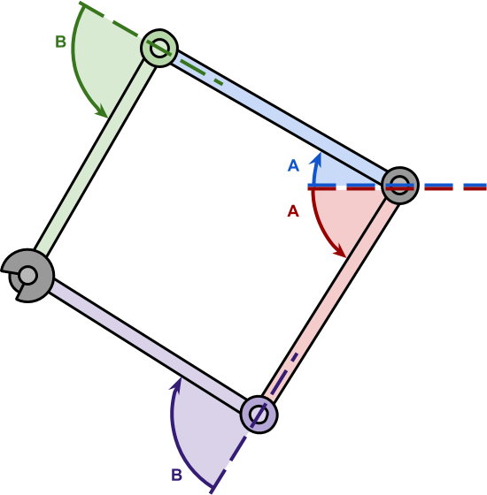
Although the corners and actually different, the conclusion essentially remains the same, with a few exceptions.
Although the corners
and actually different, the conclusion essentially remains the same, with a few exceptions.Part 2. Code

Introduction
In the previous part, we examined the inverse kinematics problem for a robot manipulator with two degrees of freedom.
In this case, the length of the manipulator is usually known
 and . If the point we want to reach is, then the configuration becomes a triangle, all sides of which are known.
Then we derived the equations for the angles
and that control the rotation of the joints of the manipulators:At first glance, they can look quite intimidating; on the other hand, their geometric interpretation is quite intuitive from the figure above.
Creating a robot arm
The first step in implementing this solution is to create a robot arm. The concept of “hinges” is unknown to the Unity engine. However, the system of parent elements available in the engine can be used to create a hierarchy of components that will behave exactly like a robot manipulator.
The idea is to use for each hinge
GameObject, so that turning its transform makes the manipulator attached to it turn. Having made the second hinge a child of the first hinge, we make them rotate as in the first figure. As a result, we get the following hierarchy:
- Root
- Hinge A
- Bone A
- Hinge B
- Bone B
- Arm
- Hinge A
Then we can add a script to the root object with a name
SimpleIKthat will rotate the hinges to reach the desired point.using System.Collections;
using UnityEngine;
namespace AlanZucconi.IK
{
public class SimpleIK : MonoBehaviour
{
[Header("Joints")]
public Transform Joint0;
public Transform Joint1;
public Transform Hand;
[Header("Target")]
public Transform Target;
...
}
}The equations derived in the previous part of the tutorial require knowing the length of the first two bones (called respectively
and ) Since the length of the bones should not change, they can be calculated in a function Start. However, this requires that the manipulator be in a good configuration when the game starts .private length0;
private length1;
void Start ()
{
length0 = Vector2.Distance(Joint0.position, Joint1.position);
length1 = Vector2.Distance(Joint1.position, Hand.position );
}Hinges
Before showing the finished version of the code, let's start with a simplified one. If we transfer equations (1) and (2) directly to the code, we will end up with something like this:
void Update ()
{
    // Расстояние от Joint0 до Target
    float length2 = Vector2.Distance(Joint0.position, Target.position);
    // Внутренний угол альфа
    float cosAngle0 = ((length2 * length2) + (length0 * length0) - (length1 * length1)) / (2 * length2 * length0);
    float angle0 = Mathf.Acos(cosAngle0) * Mathf.Rad2Deg;
    // Внутренний угол бета
    float cosAngle1 = ((length1 * length1) + (length0 * length0) - (length2 * length2)) / (2 * length1 * length0);
    float angle1 = Mathf.Acos(cosAngle1) * Mathf.Rad2Deg;
    // Угол между Joint0 и Target
    Vector2 diff = Target.position - Joint0.position;
    float atan = Mathf.Atan2(diff.y, diff.x) * Mathf.Rad2Deg;
    // Вот как они получаются в системе отсчёта Unity
    float jointAngle0 = atan - angle0;	// Угол A
    float jointAngle1 = 180f - angle1;	// Угол B
    ...
}
Math functions
 and
and  are called in Unity
 Mathf.Acosand Mathf.Atan2. In addition, the final angles are converted to degrees using Mathf.Rad2Deg, because the component Transformshould receive angles, not radians.We aim for unattainable goals
Although the code above seems to work, there is a condition under which it fails. What happens if the goal is unattainable? This is not taken into account in the current implementation, which leads to undesirable behaviors.
The usual solution is to fully stretch the manipulator towards the target. This behavior corresponds to the reach movement, which we seek to simulate.
The code shown below recognizes unattainable targets by checking whether the distance from the root to it is greater than the total length of the manipulator.
void Update ()
{
    float jointAngle0;
    float jointAngle1;
    float length2 = Vector2.Distance(Joint0.position, Target.position);
    // Угол между Joint0 и Target
    Vector2 diff = Target.position - Joint0.position;
    float atan = Mathf.Atan2(diff.y, diff.x) * Mathf.Rad2Deg;
    // Достижима ли цель?
    // Если нет, то мы растягиваемся как можно дальше
    if (length0 + length1 < length2)
    {
        jointAngle0 = atan;
        jointAngle1 = 0f;
    }
    else
    {
        float cosAngle0 = ((length2 * length2) + (length0 * length0) - (length1 * length1)) / (2 * length2 * length0);
        float angle0 = Mathf.Acos(cosAngle0) * Mathf.Rad2Deg;
        float cosAngle1 = ((length1 * length1) + (length0 * length0) - (length2 * length2)) / (2 * length1 * length0);
        float angle1 = Mathf.Acos(cosAngle1) * Mathf.Rad2Deg;
        // Вот как определяются углы в системе отсчёта Unity
        jointAngle0 = atan - angle0;
        jointAngle1 = 180f - angle1;
    }
    ...
}
Hinges
Now we have to learn how to turn the hinges. This is done by accessing the property
localEulerAnglesof the Transformhinge component . Unfortunately, we cannot change the angle zdirectly, so the vector must be copied, modified and pasted.Vector3 Euler0 = Joint0.transform.localEulerAngles;
Euler0.z = jointAngle0;
Joint0.transform.localEulerAngles = Euler0;
Vector3 Euler1 = Joint1.transform.localEulerAngles;
Euler1.z = jointAngle1;
Joint1.transform.localEulerAngles = Euler1;This completes the tutorial on inverse kinematics for two-dimensional manipulators.