Working with problematic * .dwg files in nanoCAD environment

The * .dwg format is the most popular format for storing electronic drawings. Often * .dwg files are stored for years, stored on various systems, used by different users, and because of this they can accumulate various errors. To protect yourself and your documents, before you start working with files in nanoCAD, it is recommended to perform a number of actions to check, clean and optimize them. Below we will look at the main tools and methods for working with * .dwg files.
How to find out the version of a * .dwg file?
Open the * .dwg file through a text editor such as Notepad . The first characters will indicate the version, the rest of the file will be displayed in encrypted form.
It may take extra time to open large files in Notepad.

You can find out the version of dwg in which the file is saved from the list:
AC1015 - dwg 2000
AC1018 - dwg 2004
AC1021 - dwg 2007
AC1024 - dwg 2010
AC1027 - dwg 2013
AC1032 - dwg 2018
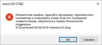
* .dwg file does not open
If for some reason the file does not open, do not panic. Let's try to restore it using utilities. When you open a drawing of this type, you will most likely see a message:
Restart the nanoCAD program and use the Document Recovery utility .
- Menu: File> Utilities> Document Recovery ...
- Command line: RECOVER
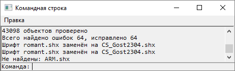
This command allows you to restore damaged documents that do not open in nanoCAD , as well as check them for errors and correct individual errors. Upon completion of the recovery, the program will provide a command line report on the corrected errors.
If the file still cannot be opened, send it to the technical support specialists, accompanying the letter with a detailed description of the problem.
How to clean * .dwg file?
Before you start working with cleaning utilities, be sure to unlock, enable and unfreeze all layers of your document, otherwise you will not be able to fix all file defects.

1. Verification of the document
- Menu: File> Utilities> Document Check
- Command line: CHECK (AUDIT)
The command is designed to identify and correct problematic drawing objects that lie outside the range. There are two modes:
- Check_Z_coordinates - check the coordinates along the Z axis of all drawing objects;
- Hatch_Check - checking the correct display of hatching within the boundaries of contours.
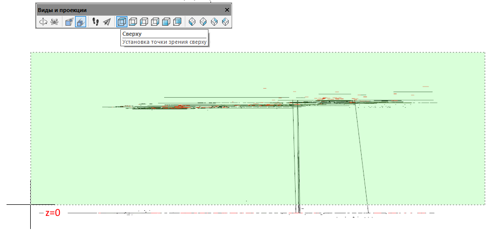
Broken Z-coordinates, in my opinion, is one of the most common ailments of the * .dwg format. They can be in the drawing for years, remaining undetected, since most often users work in the plane. To identify this problem, you need to look at the drawing from a different view. Hold Shift and use the mouse wheel to rotate the drawing in 3D space. If your drawing is flat - everything is fine, if not - it's time to fix it. You can return to the top view by clicking Top View in the <View> Views and Projections> Top menu .

Symptoms of this problem are different. Bindings work poorly, some of the objects are not displayed, the cursor disappears in the model, or the drawing works slowly. The problem is very relevant when working with large files: master plans, substrates, etc.Starting from version 7, the nanoCAD platform automatically checks the Z-coordinates when starting * .dwg files, and if a problem is found in your file, you will see the following window:
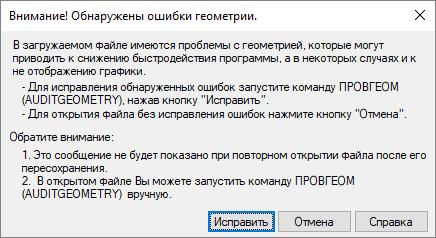
Just click Fix and the utility will transfer all the objects that have flown away. It is important to note that this function does not make your drawing completely flat, but simply transfers objects with a flying away Z coordinate closer to the zero value. If you have three-dimensional objects, they will not be destroyed. After checking the geometry, inspect your drawing in 3D - if there are any defects, it is recommended to use the Convert to 2D function .
3. Convert to 2D
- Menu: File> Utilities> Convert to 2D
- Command line: CONB2D (FLATTEN)
This function allows you to make all objects in the drawing completely flat. Therefore, if you are working with 3D polylines, you should use it with extreme caution. Here are a couple of ways that I use when working with such files:
Method number 1
In this case, you need to select all objects that lie outside the zero plane. To do this, we need:
- Turn on the side view and select all objects that are above or below zero.
- After selecting all the objects that are outside the zero plane, we switch to the top view (this is important, otherwise the function will flatten the drawing to the wrong plane for us) and, without removing the selection of objects, we call the Convert to 2D function.

Method number 2
The method is more time-consuming, but also safer.
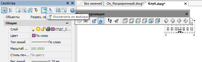
The fact is that converting to 2D destroys SPDS design objects (callouts, axes, level marks, etc.), therefore, before starting the conversion, we need to exclude these objects from the selection.
- Select all drawing objects (Ctrl + A). Go to the Properties functional panel, select design objects from the drop-down list and exclude them from the selection. We repeat this operation until there are no SPDS design objects in the selection.
- Without dropping the selection from the objects, we call the Convert to 2D function . Then the file can be checked again for errors. After checking, save the file under a different name - for example, A architecture_audit_flatten.dwg . When saving, I use versioning so that in case of any error I can return to the previous version of the file and not do all the cleaning operations from scratch.
4. Cleaning the document (purge)
- Menu: File> Utilities> Document Cleanup ...
- Command line: CLEAR, OCH, DELETE (PURGE, PU)
After starting the command, the dialog box Cleanup Document A appears, which lists the items available for deletion and a list of items that cannot be removed from the document. Select the items to be deleted from the list, or click Delete All.
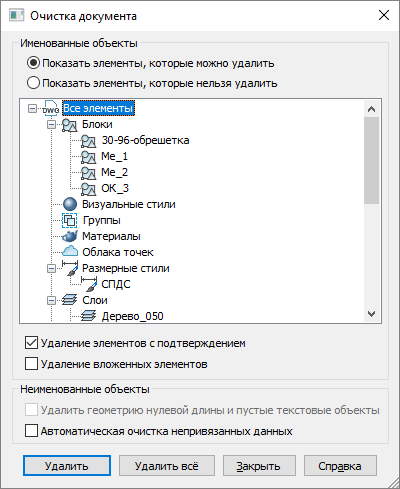
- Deleting nested items — Enables deletion of all unused named objects contained within other unused named objects.
- Automatic clearing of non-attached data - removal of outdated styles of vector data in DGN format.
Files with DGN styles weigh more than usual, although they contain little graphics. Such files may run slowly and cause a hang when saving.
- Delete zero-length geometry and empty text objects - activates the mode of removing graphic garbage. The checkbox is unavailable if there is no corresponding geometry in the document.
Such objects are hard to find in the model. Texts are visually displayed only after selection, as they have no content.
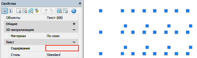
It is convenient to find them through the Drawing Manager ( Tools> Drawing Manager ). In this function panel, empty single-line and multi-line texts will be displayed as “EMPTY TEXT”.

After cleaning, save the file under a different name. I save the drawings with the postfix of the utility that I tested it with. Therefore, the name of our file will now look like this: Architecture_audit_flatten_purge.dwg.
5. Transcoding text
- Menu: File> Utilities> Text Encoding
- Command line: DECODE (TEXTDECODER)
Probably, any Russian user has at least once encountered encoding problems when, for example, file names in Explorer or text in a browser are displayed as incomprehensible icons. This problem is also familiar to users of CAD systems.

The text transcoding utility is presented as a separate drop-down window. The first thing we need to choose is the type of objects that we will recode. Such objects can be layers, styles, texts, etc.
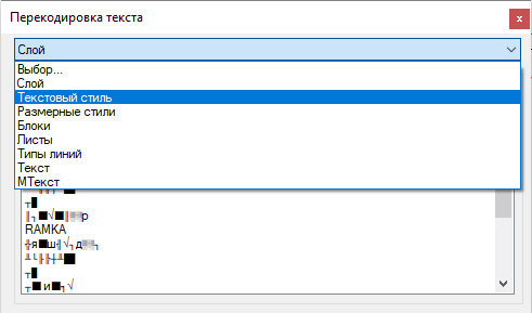
There are two decoding modes: manual and auto-selection . The first is the most accurate and very labor-intensive, the second is fast, but associated with the risk of errors. Let's take a closer look at each of them.
Manually
We select the text from the list and assign it the final encoding. Next, click Decode and look at the result in the Decoding Result window . If you have not guessed with the encoding, select another and recode again.

Auto-selection
In this mode, the program selects the final encoding on its own. Select an item from the list with the problem encoding, set the Auto -decoding decoding mode and click the Decode button . The program is not always able to correctly determine the final encoding, so the user is presented with a list of results with different encoding. From the drop-down list, select the correct representation.
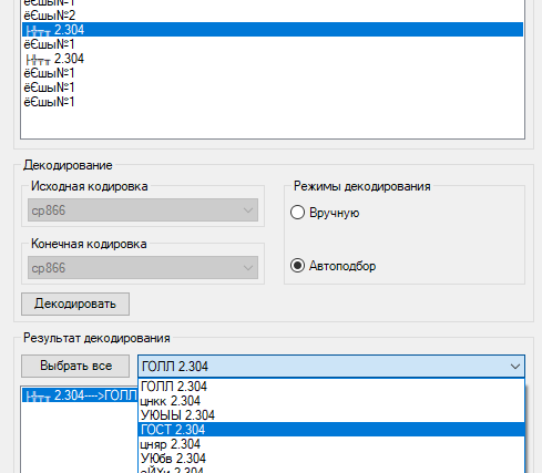
Recoding all objects
You can transcode the entire data array. To do this, we need to click the Select All button , set the decoding mode to AutoSet and click on the Recode button .

If you have to transcode a large array of objects, try to exclude from the transcoding those that are displayed correctly. You can do this by clicking on the list item with the left mouse button while holding down the Ctrl key (Ctrl + LMB).

After correcting the encoding, save the file under a different name - for example, Architecture_audit_flatten_purge_decod.dwg
6. Insert a drawing into a new file
There is another good method that can fix even the most ugly files. CAD users have been using this method for a long time, I just want to remind you about it again.
It is worth resorting to this method if cleaning and checking do not help to fix a particular defect. Attention! All drawn sheets will disappear in the drawing.
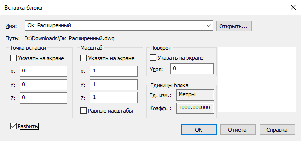
Create a new file in nanoCAD (menu File> New ). Next, you need to insert the problematic drawing into this open file as a block ( Insert menu > Block ). In the Insert block window , uncheck the box Show on the screen to insert the drawing immediately into zero coordinates. You also need to check the box next to the Split item so that the inserted drawing does not have to be broken after insertion.
After inserting the drawing in this way, the entire database of the * .dwg file will be regenerated. This way you can fix a number of errors that were in your old files. When you insert, you will also lose all the proxy objects in your drawing, so be careful when using this method. After inserting the drawing, save the file under a different name, for example, Architecture_insert.dwg.
7. Breakdown and removal of proxy objects
- Menu: Editing> Additional Tools> Removing Proxy Objects
- Menu: Editing> Additional Tools> Proxy Object Breakdown
* .dwg files may contain third-party objects created in other applications. All unidentified objects are called proxy objects (they may or may not have a graphical representation). Proxy objects create specialized applications under various CAD platforms. Probably every designer came across such objects. They cannot be edited, they do not have “pens”.
Proxy is a transit storage technology. In simple human language, it allows an application to save its object and protect it from destruction, even if you open it in another CAD system that does not have this application. Therefore, before breaking and deleting proxies, think about it: suddenly the object of a third-party application is still useful to you and you should not rush with its division into primitives.
Some specialized application developers protect their objects by not allowing them to be broken by the EXPLODE command. For such cases, nanoCAD implements special proxy breakdown and removal utilities. They work quite simply, you just need to select proxy objects and call the necessary command (breakdown and deletion). These commands are also available in the context menu of the Drawing Manager , a special tool that displays the entire structure of a * .dwg file.

Conclusion
After working with all the utilities, carefully read the final file. Sometimes complex files may require 2-3 passes with utilities. If all the necessary design data is intact and the current result suits you completely, delete the intermediate files and leave the source file architecture.dw g, and assign the name architecture_rec.dwg to the final one .
Using this marking, you will know which files you have already processed and which still need to be checked. Always work in files marked _rec.I hope the above information will help you clean up your files, simplify and speed up work in the * .dwg environment, and also avoid critical errors and data loss.
Have a good design!
Sergey Spirin, mahbak
Nanosoft CJSC