Decrease cooler noise and speed
Hello, today I will tell you how to simply reduce the speed and noise of the cooler.
We can do without wood and flash drives. This is my first post, in the following I will talk about how to make video surveillance, a liquid cooling system, automated (programmable) lighting and much more delicious, we will solder, drill and flash the chips, but for now, let's start with the simplest, but nonetheless Highly efficient reception: mounting a variable resistor. The noise from the cooler depends on the number of revolutions, the shape of the blades, the type of bearings and other things. The higher the number of revolutions, the more efficient the cooling, and the more noise. 1600 rpm are not always and not always needed. and if we lower them, the temperature will rise by several degrees, which is not critical, but the noise can disappear altogether!
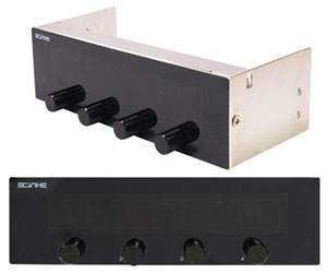
On modern motherboards, integrated control of the speed of coolers that are powered by it is integrated. In BIOS, you can set a “reasonable” cut, which will change the speed of coolers depending on the temperature of the cooled chipset. But on old and budget boards there is no such option, and what about other coolers, for example, a PSU cooler or a case cooler? To do this, you can mount a variable resistor in the cooler power circuit, such systems are sold, but they cost incredible money, given that the cost of such a system is about 1.5 - 2 dollars! Such a system sells for $ 40: you can make it yourself by using a dongle from your system unit as a socket (a dummy in the basket where DVD / CD drives are inserted), and you will learn about other things from this post.
Next, I will describe the process using the PSU as an example, but it is identical in all cases.
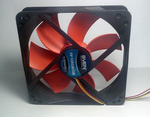
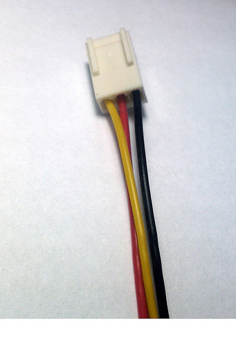
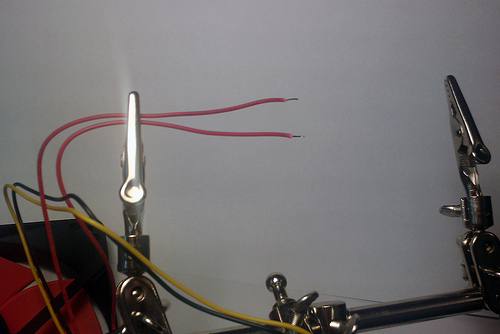
Because I broke off 1 blade from the cooler on the PSU, I bought a new one on ball bearings, it is much quieter than usual: Now we need to find a power cable, into the gap of which we mount a resistor. This cooler has 3 wires: black (GND), red (+ 12V) and yellow (tachometric contact). Cut red, strip and tin. Now we need a variable resistor with a resistance of 100 - 300 Ohms and a power of 2-5 watts . My cooler is rated at 0.18 A and 1.7 watts. If the resistor is designed for less power than the power in the circuit, it will heat up and eventually burn out. As exdeniz suggests, PPB-3A 3W 220 Ohm is perfect for our purposes
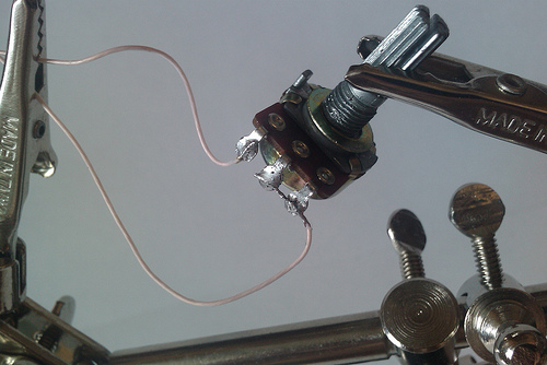
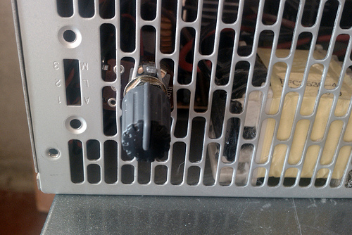
. Such as I have a variable resistor, 3 pins. I will not go into details, just solder 1 wire to the middle pin and one extreme, and the second to the remaining extreme (You can find out the details with a multimeter / ohmmeter. Thanks to guessss_who for comment ). Now we mount the fan in the case and find a suitable place for mounting the resistor. I decided to insert it like this: The resistor has a nut for fastening to the plane. Please note that the case is metal and can close the contacts of the resistor and it will not work, so cut out the insulator gasket from plastic or cardboard. My contacts do not close, fortunately, so there are no gaskets in the photo.

Now the most important thing is a field test.
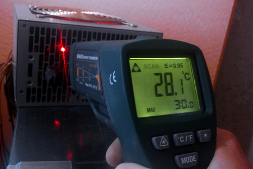
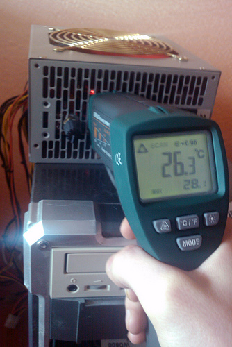
I turned on the system, opened the PSU case and found the hottest part with a pyrometer (this is an element, it looks like a transistor that is cooled by a radiator). Then he closed it, unscrewed the resistor to maximum speed and waited 20-30 minutes ... The element warmed up to 26.3 ° C. Then I set the resistor to half, I can no longer hear the noise, I waited 30 minutes again ... The element warmed up to 26.7 ° C. Again I lower the revs to a minimum (~ 100 Ohm), wait 30 minutes, I don’t hear any noise from the cooler at all ... The element has warmed up to 28.1 ° C.
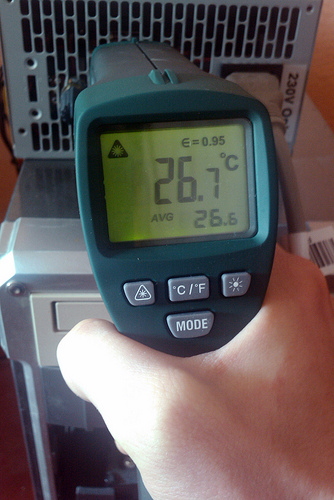

I do not know what this element is and what its working temperature is, but I think that it will withstand another 5-10 degrees. But if we take into account that there was no noise on the “half” of the resistor, then we don’t need anything else! =)
Now you can make a panel like I cited at the beginning of the article and it will cost you a penny.
Thanks.
UPD: Thanks to the gentlemen from the comments, for the reminder of the watts.
UPD: If you are interested in the topic and you know what a soldering iron is, then you can easily assemble an analog reobass. As fleshy tells us , in the article Analog Reobas , this wonderful device is described. Even if you never soldered the boards, you can collect reobas. The article has a lot of text, which I don’t understand, but the main thing: Composition, Scheme, Motazh (in this section there are links to all the necessary articles on soldering ).
We can do without wood and flash drives. This is my first post, in the following I will talk about how to make video surveillance, a liquid cooling system, automated (programmable) lighting and much more delicious, we will solder, drill and flash the chips, but for now, let's start with the simplest, but nonetheless Highly efficient reception: mounting a variable resistor. The noise from the cooler depends on the number of revolutions, the shape of the blades, the type of bearings and other things. The higher the number of revolutions, the more efficient the cooling, and the more noise. 1600 rpm are not always and not always needed. and if we lower them, the temperature will rise by several degrees, which is not critical, but the noise can disappear altogether!

On modern motherboards, integrated control of the speed of coolers that are powered by it is integrated. In BIOS, you can set a “reasonable” cut, which will change the speed of coolers depending on the temperature of the cooled chipset. But on old and budget boards there is no such option, and what about other coolers, for example, a PSU cooler or a case cooler? To do this, you can mount a variable resistor in the cooler power circuit, such systems are sold, but they cost incredible money, given that the cost of such a system is about 1.5 - 2 dollars! Such a system sells for $ 40: you can make it yourself by using a dongle from your system unit as a socket (a dummy in the basket where DVD / CD drives are inserted), and you will learn about other things from this post.

Next, I will describe the process using the PSU as an example, but it is identical in all cases.
Because I broke off 1 blade from the cooler on the PSU, I bought a new one on ball bearings, it is much quieter than usual: Now we need to find a power cable, into the gap of which we mount a resistor. This cooler has 3 wires: black (GND), red (+ 12V) and yellow (tachometric contact). Cut red, strip and tin. Now we need a variable resistor with a resistance of 100 - 300 Ohms and a power of 2-5 watts . My cooler is rated at 0.18 A and 1.7 watts. If the resistor is designed for less power than the power in the circuit, it will heat up and eventually burn out. As exdeniz suggests, PPB-3A 3W 220 Ohm is perfect for our purposes


. Such as I have a variable resistor, 3 pins. I will not go into details, just solder 1 wire to the middle pin and one extreme, and the second to the remaining extreme (You can find out the details with a multimeter / ohmmeter. Thanks to guessss_who for comment ). Now we mount the fan in the case and find a suitable place for mounting the resistor. I decided to insert it like this: The resistor has a nut for fastening to the plane. Please note that the case is metal and can close the contacts of the resistor and it will not work, so cut out the insulator gasket from plastic or cardboard. My contacts do not close, fortunately, so there are no gaskets in the photo.


Now the most important thing is a field test.
I turned on the system, opened the PSU case and found the hottest part with a pyrometer (this is an element, it looks like a transistor that is cooled by a radiator). Then he closed it, unscrewed the resistor to maximum speed and waited 20-30 minutes ... The element warmed up to 26.3 ° C. Then I set the resistor to half, I can no longer hear the noise, I waited 30 minutes again ... The element warmed up to 26.7 ° C. Again I lower the revs to a minimum (~ 100 Ohm), wait 30 minutes, I don’t hear any noise from the cooler at all ... The element has warmed up to 28.1 ° C.


I do not know what this element is and what its working temperature is, but I think that it will withstand another 5-10 degrees. But if we take into account that there was no noise on the “half” of the resistor, then we don’t need anything else! =)
Now you can make a panel like I cited at the beginning of the article and it will cost you a penny.
Thanks.
UPD: Thanks to the gentlemen from the comments, for the reminder of the watts.
UPD: If you are interested in the topic and you know what a soldering iron is, then you can easily assemble an analog reobass. As fleshy tells us , in the article Analog Reobas , this wonderful device is described. Even if you never soldered the boards, you can collect reobas. The article has a lot of text, which I don’t understand, but the main thing: Composition, Scheme, Motazh (in this section there are links to all the necessary articles on soldering ).
