Learn OpenGL. Lesson 4.3 - Mixing Colors
- Transfer
- Tutorial

Color mixing
Mixing in OpenGL (and other graphical APIs, approx. Per. ) Is the technique that is usually associated with the implementation of object transparency. The translucency of an object implies that it is not flooded with one solid color, but combines the shade of its material in various proportions with the colors of objects behind. As an example, you can take colored glass in a window: glass has its own shade, but in the end we observe a mixture of the shade of glass and all that is visible behind the glass. Actually, from this behavior the term blending arises, since we observe the resulting color, which is a mixture of the colors of individual objects. Thanks to this, we can see through translucent objects.
Content
Part 1. Getting Started
Part 2. Basic lighting
Part 3. Download 3D models
Part 4. Advanced OpenGL Features
Part 5. Advanced Lighting
Part 6. PBR
- Opengl
- Window creation
- Hello window
- Hello triangle
- Shaders
- Textures
- Transformations
- Coordinate systems
- Camera
Part 2. Basic lighting
Part 3. Download 3D models
Part 4. Advanced OpenGL Features
- Depth test
- Stencil test
- Color mixing
- Clipping faces
- Frame buffer
- Cubic cards
- Advanced data handling
- Advanced GLSL
- Geometric shader
- Instancing
- Smoothing
Part 5. Advanced Lighting
- Advanced lighting. Blinn-Fong model.
- Gamma correction
- Shadow cards
- Omnidirectional shadow maps
- Normal mapping
- Parallax mapping
- HDR
- Bloom
- Deferred rendering
- SSAO
Part 6. PBR
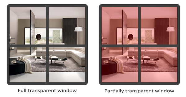
Translucent objects can be completely transparent (all colors pass through) or partially transparent (transmits light, but also adds its own shade). In computer graphics, it is customary to indicate the degree of opacity of the so-called alpha component of the color vector. The alpha component is the fourth element of the color vector, and you must have noticed it more than once in previous lessons. However, until that moment, we always kept this value equal to 1.0, which is equivalent to full opacity. By setting the alpha component to 0.0, we would achieve full transparency. A value of 0.5 would imply that the final color of the object is 50% set by its material, and 50% is set by the objects behind.
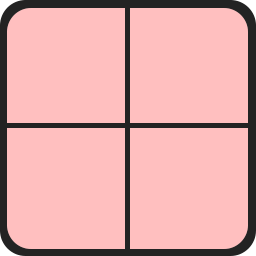
All the textures we used so far contained 3 color components: red, blue and green. Some texture formats also allow you to save the fourth alpha component for each texel. This value indicates which parts of the texture are translucent and how much. For example, this window glass texture has an alpha component set to 0.25 for glass areas and 0.0 for the frame. In other circumstances, the glass parts would be completely red, but due to 75% transparency, the color is mostly determined by the background of the current web page.
Soon we will add this texture to a new scene, but, for starters, we will discuss a simpler technique for achieving transparency in cases where either full transparency or full opacity is needed.
Discarding Fragments
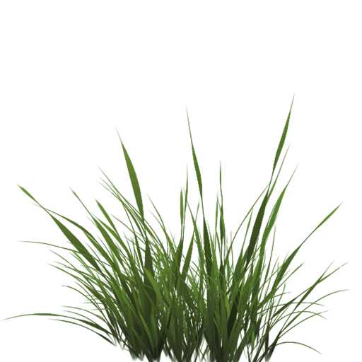
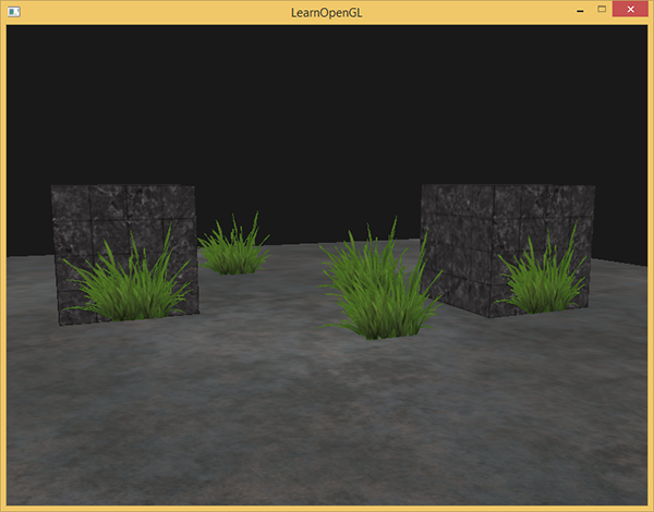
In some cases, partial transparency is not required: you must either display something or nothing based on the color value of the texture. Imagine a bunch of grass: the simplest implementation of the bunch would require a grass texture on a 2D quad located in your scene. However, the quad form does not help much in the task of simulating a grass beam - it would not hurt us to hide parts of the superimposed texture, leaving some others.
The texture presented below exactly represents the described case: its sections are either completely opaque (alpha component = 1.0) or completely transparent (alpha component = 0.0) - no average values. You may notice that where there is no image of blades of grass, the site background is visible, and not the color of the texture:
Thus, when placing vegetation in our scene, we would like to see only parts of the texture that correspond to parts of the plant, and discard the rest of the texture filling the polygon. That is, discard fragments containing transparent parts of the texture without saving them in the color buffer. But before we get our hands dirty with fragments, we need to learn how to load textures with an alpha channel.
To do this, we don’t have to change much in the familiar code. The loader function from stb_image.h automatically loads the alpha channel of the image, if one is available. But you need to explicitly indicate to OpenGL when creating the texture that it uses the alpha channel:
glTexImage2D(GL_TEXTURE_2D, 0, GL_RGBA, width, height, 0, GL_RGBA, GL_UNSIGNED_BYTE, data); Also make sure that in the fragment shader you select into a vector with 4 components, so as not to be left with only RGB values:
void main()
{
    // FragColor = vec4(vec3(texture(texture1, TexCoords)), 1.0);
    FragColor = texture(texture1, TexCoords);
}
Now that we’ve figured out loading textures with transparency, it's time to throw a few tufts of grass around the scene used in the depth test tutorial .
Let's create a small vector storing the position of grass bunches in the form of glm :: vec3 :
vector vegetation;
vegetation.push_back(glm::vec3(-1.5f,  0.0f, -0.48f));
vegetation.push_back(glm::vec3( 1.5f,  0.0f,  0.51f));
vegetation.push_back(glm::vec3( 0.0f,  0.0f,  0.7f));
vegetation.push_back(glm::vec3(-0.3f,  0.0f, -2.3f));
vegetation.push_back(glm::vec3( 0.5f,  0.0f, -0.6f));
Each grass object is rendered as a single quad with the grass texture assigned to it. Not the most exciting method of simulating grass in 3D, but much more effective than using polygonal models. With the help of small tricks, such as adding another pair of rotated quads with the same texture in the same position, good results can be achieved.
Since we assign the grass texture to quad, we need a new VAO (vertex array object), fill in the VBO (vertex buffer object) and set the corresponding pointers to the vertex attributes. Next, after rendering the surface of the floor and cubes, we display our grass:
glBindVertexArray(vegetationVAO);
glBindTexture(GL_TEXTURE_2D, grassTexture);
for(unsigned int i = 0; i < vegetation.size(); i++)
{
    model = glm::mat4(1.0f);
    model = glm::translate(model, vegetation[i]);
    shader.setMat4("model", model);
    glDrawArrays(GL_TRIANGLES, 0, 6);
}
Running the program will produce this result:
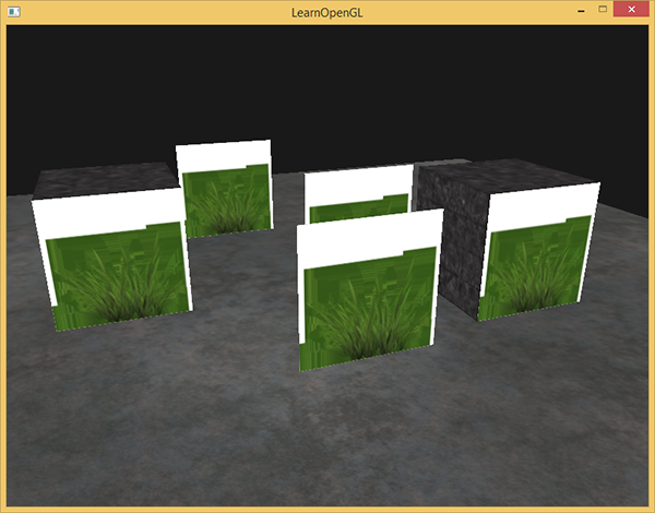
This happened because OpenGL itself does not know what to do with the values of the alpha channel, nor when to use fragment dropping. All this we must specify manually. Fortunately, with the help of shaders, everything is done quite simply. There is a built-in discard directive in GLSL , the call of which leads to the cessation of further processing of the current fragment without falling into the color buffer. From here a solution emerges: we check the value of the alpha component of the texture element and, if it is less than a certain threshold, discard it:
#version 330 core
out vec4 FragColor;
in vec2 TexCoords;
uniform sampler2D texture1;
void main()
{
    vec4 texColor = texture(texture1, TexCoords);
    if(texColor.a < 0.1)
        discard;
    FragColor = texColor;
}
In this code, we discard the fragment if the alpha component of the texture sample is less than 0.1. Such a shader will provide us with the output of only those fragments that turned out to be quite opaque:
I note that when fetching texture boundaries at OpenGL, it interpolates the value on the border with the value from the next value obtained by repeating the texture (since we set the texture repeat option to GL_REPEAT ). For normal texture applications, this is normal, but for our texture with transparency it is not good: the completely transparent texel value at the upper border is mixed with the fully opaque lower border texels. As a result, a translucent colored frame may appear around a quad with our texture. To avoid this artifact, you need to set the repeat parameter to GL_CLAMP_TO_EDGE when using textures with transparency.glTexParameteri( GL_TEXTURE_2D, GL_TEXTURE_WRAP_S, GL_CLAMP_TO_EDGE); glTexParameteri( GL_TEXTURE_2D, GL_TEXTURE_WRAP_T, GL_CLAMP_TO_EDGE);
An example code is here .
Mixing
Despite the fact that discarding fragments is a convenient and simple method, it does not make it possible to apply partial mixing of translucent colors. For rendering images with objects with different degrees of opacity, we must enable the blending mode. This is done, as for most OpenGL modes:
glEnable(GL_BLEND); Now, turning on mixing, it's worth figuring out how exactly this works.
OpenGL mixing is performed using the following formula
Where
 Is the color vector of the source. This is the color value obtained from the texture.
 Is the color vector of the receiver. This is the color value currently stored in the color buffer.
 - source multiplier. Specifies the degree to which the alpha component affects the color of the source.
 - receiver multiplier. Specifies the degree to which the alpha component affects the color of the receiver.
 After the execution phase of the fragment shader and other tests (stencil and depth tests, approx. Per. ), This mixing formula is free to do anything with the colors of the processed fragments and the colors stored in the buffer at the moment (color values of the fragments from the previous frame). OpenGL automatically assigns source and receiver roles, but we can set the factors for them ourselves. To get started, consider the following example:
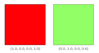
There are two squares and translucent green we would like to draw on top of opaque red. In this case, the color of the receiver will be the color of the red square, which means that it must be entered in the color buffer first.
The question arises: how to choose the values of the factors in the mixing formula? Well, at least we should multiply the green color of the second square by its alpha component value, therefore
we take equal to the alpha component of the color vector of the source, i.e. 0.6. Based on this, it would be reasonable to assume that the receiver will provide a contribution to the result proportional to the degree of transparency that remains available. If the green square provides 60% of the total, then the red square should get 40% (1. - 0.6). So the multiplierset equal to the difference of unity and the alpha component of the source color vector. As a result, the mixing expression takes the following form:The result of mixing will be a 60% color consisting of the original green and 40% of the original red - this is a slurred brown color:
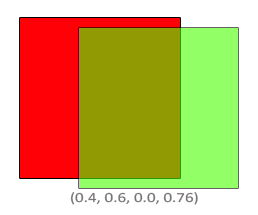
The result will be buffered, replacing the old values.
Well, how do we let OpenGL understand what mixing coefficient values we want to use? Fortunately for us, there is a special function:
glBlendFunc(GLenum sfactor, GLenum dfactor)It takes two parameters that determine the values of the coefficients of the source and receiver. The OpenGL API defines an exhaustive list of values for these parameters, which allows you to configure the mixing mode as you like. Here I will give the most “running” parameter values. I note that a constant color vector
 set separately by glBlendColor .
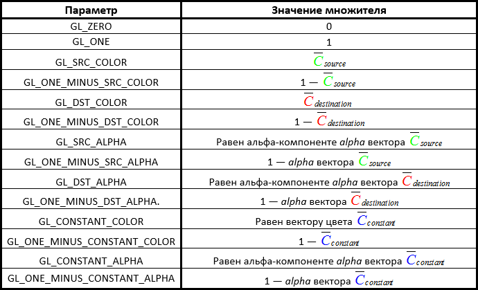
To get the result described in the two-squares example, we should choose such parameters that the source coefficient is equal to alpha (alpha component value) of the source color, and the receiver coefficient is equal to 1 - alpha . Which is tantamount to a call:
glBlendFunc(GL_SRC_ALPHA, GL_ONE_MINUS_SRC_ALPHA); Separate adjustment of coefficients for RGB and alpha components is also possible through the glBlendFuncSeparate function :
glBlendFuncSeparate(GL_SRC_ALPHA, GL_ONE_MINUS_SRC_ALPHA, GL_ONE, GL_ZERO);Such a call adjusts the mixing of the RGB component as in the previous example, additionally indicating that the alpha component of the result will be equal to the alpha component of the source.
OpenGL also allows for even more flexible customization of the mixing formula, allowing the choice of the operation to be performed between the components of the formula. By default, the source and receiver components are added up, but subtraction can be selected, if this is the intention. Defines the behavior of a function
glBlendEquation(GLenum mode)And there are three options for the parameter value:
- GL_FUNC_ADD : default, add components:
 .
. - GL_FUNC_SUBTRACT : subtracts the receiver component from the source component:
 .
. - GL_FUNC_REVERSE_SUBTRACT : subtracts the source component from the receiver component:
 .
.
Normally, glBlendEquation is not required, since the default mode is GL_FUNC_ADD and so is suitable for most applications. But for non-standard approaches and attempts to create an unusual visual solution, other modes of calculating the mixing formula may well come in handy.
Translucent Texture Render
So, we got acquainted with how the library performs mixing. It's time to put this knowledge into practice by creating a couple of transparent windows. We use the same scene as at the beginning of the lesson, but instead of grass bunches we will place objects with the window texture already mentioned at the beginning of the lesson .
To begin, turn on the mixing mode and select its parameters:
glEnable(GL_BLEND);
glBlendFunc(GL_SRC_ALPHA, GL_ONE_MINUS_SRC_ALPHA);
Since we turned on blending, we no longer need to discard transparent fragments. The fragment shader code will return to its previous state:
#version 330 core
out vec4 FragColor;
in vec2 TexCoords;
uniform sampler2D texture1;
void main()
{
    FragColor = texture(texture1, TexCoords);
}
Now, when processing each fragment, OpenGL mixes the color of the fragment being processed and the color stored in the buffer according to the value of the alpha component of the first. Since the glass part of the window is translucent, we should see the rest of the scene behind the window:
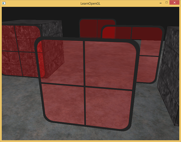
However, looking closely, you can see that the render is incorrect. For some reason, the translucent parts of the closest window to us overlap other windows in the background!
The reason is that the depth test does not take into account the transparent fragment or not when processing. As a result, all fragments of a quad with a window texture pass the depth test in one way, whether they belong to the glass part or not. Despite the fact that old fragments should remain behind the glass parts, the depth test will reject them.
Bottom line: you can not display translucent objects anyway, as well as hoping that the depth test and mixing themselves will decide how to do everything correctly. To ensure the correct rendering of windows that are blocked by other windows, we first need to display the windows that are far away. Thus, we ourselves need to sort the windows by position from the farthest to the closest and display in accordance with this order.
I note that for cases with full transparency (the case with grass), the operation of dropping fragments does not cause the described problem, since mixing does not occur.
Preserving Render
For the mixing to work correctly when rendering multiple objects, it is necessary to start the output from the farthest and end with the closest. Opaque objects that do not require mixing can be displayed in the usual manner using a depth buffer, sorting is not required here. But the opaque part of the scene must be rendered before the output of elements using blending. As a result, the procedure for rendering a scene containing both opaque and transparent objects is as follows:
- Print all opaque objects.
- Sort transparent objects by deletion.
- Draw transparent objects in sorted order.
One way to sort is by arranging based on the distance from the object to the observer. This value is determined as the distance between the position vectors of the camera and the object itself. Next, we will save this distance along with the position vector of the object in the map container of the C ++ standard library. The associative container map will automatically ensure the ordering of stored elements based on the key values, so that we only need to enter all the distance-position pairs of objects:
std::map sorted;
for (unsigned int i = 0; i < windows.size(); i++)
{
    float distance = glm::length(camera.Position - windows[i]);
    sorted[distance] = windows[i];
}
As a result, we will have a container with the positions of the window objects sorted by distance from the smallest to the largest.
At the time of rendering, we need to go through the container in the reverse order (from the largest to the smallest) and draw the windows in the appropriate positions:
for(std::map::reverse_iterator it = sorted.rbegin(); it != sorted.rend(); ++it)
{
    model = glm::mat4(1.0f);
    model = glm::translate(model, it->second);
    shader.setMat4("model", model);
    glDrawArrays(GL_TRIANGLES, 0, 6);
}
Here we use a reverse iterator for the container to ensure that it goes through it in the reverse order. Each window object is shifted to the corresponding position and drawn. A relatively simple code modification led to a complete resolution of the previously identified problem:
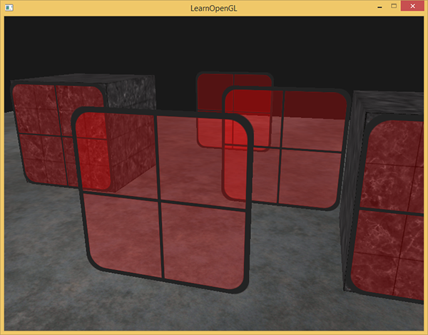
As you can see, the scene is now displayed correctly. The source code for the example is here .
It is worth noting that a simple sorting by range, although it worked well in this case, does not take into account such features as rotations, scaling, and other transformations of objects. Also, objects of complex shape would require a more sophisticated sorting metric than just the distance from the camera.
In addition, sorting is not given for free: the complexity of this task is determined by the type and composition of the scene, and the process itself requires additional computational costs. There are also more advanced methods for outputting scenes containing both transparent and opaque objects: for example, the Order Independent Transparency (OIT) algorithm) But coverage of this topic is beyond the scope of the lesson. And you have to do with the usual implementation of mixing. But there is no reason for sadness, knowing the limitations of the technology and being careful, you can achieve quite impressive results!
PS : And again in the comments a useful link . You can see live how the choice of blending modes affects the outcome.
PPS : Eanmos and I have a telegram conf for coordinating transfers. If you have a serious desire to help with the translation, then you are welcome!