November 22, 2017 at 11:06
Programming for ARM TrustZone. Secure monitor
We continue our series of articles dedicated to the centenary of the Great October ... ARM TrustZone.
Today we will understand what Secure World, Normal World are, and how two OSs interact at the software level - trusted (TEE) and guest. We will find out what is needed and how Secure Monitor works, how interrupts from devices are handled.
If you are ready - welcome to cat.
In a previous article, I talked about hardware implementation. There is everything about the hardware division of the worlds, how to prevent the guest OS from trusted memory and peripherals, and so on. Let’s take one thought from there as a binding:
From a software implementation point of view, that's all we need. The hardware is on the other side of the abstraction, observing only NS, and the software is not only executed differently at NS = 0 and 1, but it can also change this bit.
In both modes (NS = 0 and NS = 1), the processor can fully work, so much so that in each mode there can be its own OS:
Each OS will have its own virtual memory card, its own applications, interrupts, drivers, and so on.
Of course, we do not always have two OSes running on ARM. The trusted code may not be a full-fledged OS, but some kind of small security monitor. Or may be completely absent. But in smartphones and tablets, the absence of a trusted OS is rare, there are mainly TEE (trusted OS) and a regular OS (for example, Android).
Just do not take the name TEE, Trusted Execution Environment, at face value. If TEE is called trusted, it means that someone trusts its code, because the code leads to the achievement of its goals. Maybe his goal is to destroy the universe, who knows? You do not see source codes.
Processors always start in Secure mode. There are many ARMv7A processors where Security Extensions are disabled. And then they always work as Secure. For example, everyone’s favorite Sitara.
But in any case - processors always start in Secure mode.
The boot loader is the first to participate in the boot process, and in the case of TrustZone, one of the implementations of the Trusted Boot idea is used - a mechanism that verifies the signature of an image before it is launched. The general algorithm here is this:
The public key to verify the signature in the processor is flashed once, and after that only the primary bootloader, signed by the private part of this key, can be started. There is also a field for abuse by large manufacturers.
Read more about ARM loading in this article .
Next, the bootloader will verify the signature of the trusted OS (TEE) and run TEE. That initializes everything that is needed in TrustZone, leaves Secure mode and transfers control to the guest OS (for example, Linux).
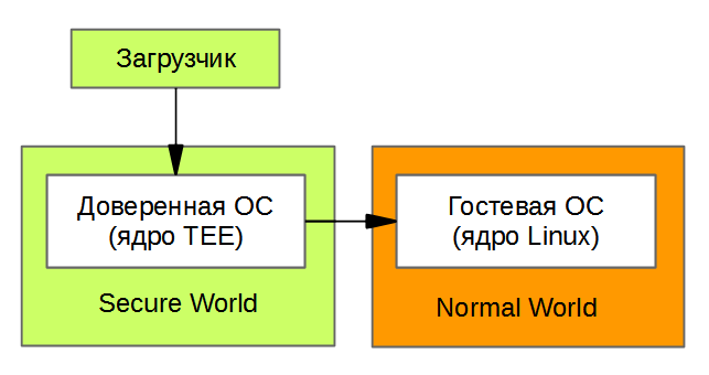
If no TEE is used, and control is transferred directly from the bootloader to Linux, then Linux works in Secure mode. This, however, does not make it a safe OS: without a barrier between Secure World and Normal World, there is no trusted OS.
Note that without Trusted Boot, TEE security would be compromised, since it could be replaced by changing the bootloader. The entire authentication chain provided by the binary signatures is important.
The picture shows the two OSs that we just downloaded. The guest OS can call TEE functions, for this it uses Secure Monitor.
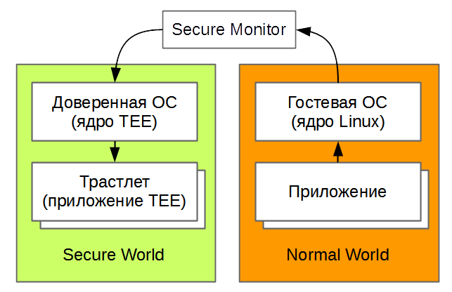
In this article we will understand what kind of Secure Monitor is, how it is used and how it works.
ARMv7A has quite a few modes of operation. In the picture, they are divided into levels PL0, PL1, PL2 and some of the levels of Secure, and some - Non-secure.
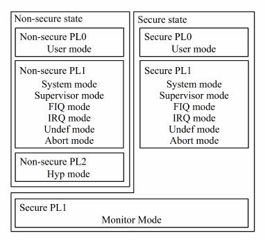
PL0 is an unprivileged mode in which regular programs are executed on the OS. Each program is launched with its own memory card configured through the MMU, so it cannot get into other programs like that. But she can’t get into the OS either, because the OS itself is configured that way. To access the OS, the application makes a system call (Supervisor Call, SVC command), and the processor jumps to Supervisor mode, PL1.
All main OS code is executed in Supervisor (SVC) mode, at the PL1 level. Here, the OS kernel also has its own MMU table, and the kernel sees the memory differently from applications. By the way, the kernel does not have to see all the pages of the application’s memory, it will be less secure.
Another important kernel mode is IRQ. They get there when interrupts are triggered. IRQ is at the PL1 level, and that's why all the normal Linux device drivers work at the kernel level. Paired IRQ FIQ mode is a quick interrupt. It is not used at all in Linux, but they found a use for it in the TrustZone implementation - we will talk about this later.
There are still modes Undef, Abort - these are exceptions when the program is running. If the OS application (or kernel code) tries to execute an invalid command, Undef will happen, if it accesses the memory forbidden to it, there will be Abort. I already wrote about this in a previous article. In the TrustZone implementation, we can choose whether Abort will be processed in the guest OS (Linux) or redirected to the trusted OS (TEE). In the latter case, we can, for example, record the attempt of the guest OS to get into the trusted OS area.
System abandoned and forgotten is rarely, if ever, used.
All of the above modes are available in both Secure and Non-Secure modes. At the same time, for example, Secure Supervisor and Non-Secure Supervisor are separate modes. They have different MMU tables, different access rights (due to the NS-bit), their data is stored in different cache lines, etc.
It is because of the duplication of Secure and Non-Secure modes on the same core that two OSs can be launched.
In the figure above there were a couple more modes:
HYP mode is used for hardware virtualization, as in VMWare. It is at the PL2 level - it is even more important than the guest OS kernel and can allow and deny everything there, just like TEE. But we will not talk about virtualization in this article at all for two reasons: firstly, few ARMv7 processors and software with its support, and secondly, from Virtualization Extensions in ARM everything becomes even more confusing. So it's better to leave virtualization aside for now.
But we really need the Secure Monitor mode, it is made to switch between Secure and Non-Secure OC. Let's look at it from all sides.
We have two full-fledged OSs, and they differ globally only in the NS bit:
After all, it is logical that a guest OS cannot change its NS bit and gain Secure privileges? Absolutely logical. It is less expected that Secure OS cannot take it and switch to Non-Secure mode like this, changing NS to 1. But this is also the case.
The fact is that switching between modes turned out to be a bit more complicated than changing one bit:
That's for this and came up with Secure Monitor mode. They get there using the “SMC # 0“ call, which stands for Secure Monitor call. Moreover, the Secure code must call “SMC # 0“ to switch to Non-Secure. And Non-Secure's Secure jumps too.
In general, an SMC call is similar to an operating system system call (SVC):
The difference is that the return from the system call is not the same as the call itself, but the transition between Secure and Non-Secure is symmetrical through SMC # 0.
Three features of the Secure Monitor mode enable it to perform a Secure / Non-Secure context switching.
For example, we want TEE to sign some document to us. We put the data about the document in the processor registers, for example, like this:
We call SMC # 0 to call TEE. In response, we expect from TEE the signature in the indicated buffer and the result code in the R0 register in order to understand whether the operation was successful or not.
That is, there is a certain protocol of exchange between the guest OS and TEE. In ARM, in the general case, you can behave as you like and come up with any exchange concepts, but there is an exchange mechanism accepted by everyone, described in ARM SMC calling convention . It describes which registers are used to transmit the command code, data, return values, and so on.
To begin with, the TEE initialization code writes the address of the Secure Monitor entry point (subroutine address) into the Monitor mode exception vector table pointed to by the MVBAR register.
The MVBAR register is available only in Secure mode and points to a special table of exception vectors that is used only when switching to Secure Monitor mode.
ARM also has a regular vector table, which indicates entry points to SVC, IRQ, FIQ, and so on. This table is located by default at address 0x00000000, but the address can be configured by the VBAR register.
Of course, for the operation of two OSs, two registers are provided there: Secure VBAR and Non-secure VBAR. Which one is available depends on the NS bit.
So, MVBAR is not used for SVC, IRQ, and so on, but only for SMC and a couple of exceptions that can be configured to get into Monitor Mode. For example, we can configure Abort and FIQ to get into Secure Monitor, and thus catch these exceptions.
When initialized, TEE also sets the address of the stack head for Secure Monitor, and you're all set, as they say overseas.
You can see an example of the implementation of Secure Monitor in the OP-TEE source code, the code is really simple: https://github.com/OP-TEE/optee_os/blob/master/core/arch/arm/sm/sm_a32.S .
Now let's see what happens when the SMC # 0 command is invoked from the guest OS.
Here is a very simplified description of what you will see in the code above. There, operations are not even all performed in the same order. The goal was to convey the general meaning, nothing more.
In fact, that's almost all that Secure Monitor does - it transfers control to Secure OS. When Secure OS finishes the call, it will also call SMC # 0. Secure Monitor will understand by NS = 0 that it is now Secure, and you need to return to Non-Secure, and will do the same commands, but a little vice versa.
If you got into understanding the code, then here is another hint under the spoiler:
If you look at OP-TEE code, all calls from Non-Secure World go to processing in Secure, and Secure Monitor does not process anything. At OP-TEE, he works as a gatekeeper.
UPDATE: Dear lorc, clarifies that the implementation of Secure Monitor in ARM Trusted Firmware not only switches modes, it also performs a number of system functions, for example, power management. See his comment.
Guest OS, as a rule, is not very good and knows that it is guest. Configures memory, interrupts, performs tasks. Everything works as it should, until it runs into some kind of restriction imposed on it by TEE. If it flies, Abort will happen, as we wrote in the last article.
At the same time, the guest OS will load a bunch of drivers, it will assign interrupts and interrupts to the devices to the guest OS. And why, one asks, into her? It may well be that TEE wants to control some devices in exclusive mode and receive their interruptions from them. Now we will understand how the two OSes share interrupts.
In the ARM processor, the main interrupt controller is one (let it be GICv2), there are no separate controllers for Secure and Non-Secure.
If an interrupt occurs, then GICv2 will by default put it in Secure mode. Then, if an interrupt occurred, the vector from Secure VBAR will be loaded.
But if we run TEE and Linux in parallel, we need to somehow divide the interrupts. It doesn’t matter if all interrupts come only in TEE (Secure) or Linux (Non-secure).
Therefore, in GICv2, as part of supporting Security Extensions, they came up with the idea of grouping interrupts (register GICD_IGROUP):
With this implementation, you can start Linux without any TEE - and then it will run in Secure mode by default, configure itself a Secure VBAR, all interrupts will go to it (we wrote about VBAR above). And if Linux is running in guest mode, then TEE will preconfigure all the unnecessary interrupts on Group 1, and Linux will start in Non-Secure mode. Linux will configure a Non-Secure VBAR for itself, and all its interrupts will go to it. Idyll and software compatibility , the GIC driver in Linux should not know whether it works in Secure or guest mode.
Well, it would seem that everything is fine and understandable. If Secure-interrupt occurred, the vector from Secure VBAR will be loaded, otherwise Non-Secure VBAR.
So no! We remember that you can’t just switch from Secure mode to Non-Secure just like that, for this we have Secure Monitor.
Therefore:
Dry residue - Secure interrupt can occur in Non-Secure mode, and then it will go through Secure Monitor. The mechanism of its work, described above, now needs to figure out whether it is sent to interruption, and accordingly process everything. And there everything is in the OP-TEE code, look.
A very useful table on this subject is here: http://infocenter.arm.com/help/topic/com.arm.doc.faqs/ka16352.html
But that's not all! In fact, for this to work, you still need to configure something else. In the SCR register, which is already familiar to us, there are bits that configure which interrupts and exceptions should be sent to Secure Monitor and which should be processed via VBAR.
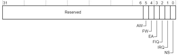
In the picture - SCR from ARM Cortex-A5. The EA, FIQ, and IRQ bits affect routing, respectively, External Abort, and FIQ, and IRQ.
Unfortunately, there are no IRQ Group 0 and IRQ Group 1, and you can only either send all IRQ to Secure Monitor, or leave it as it is, via VBAR. As it is, it will not suit us. Therefore, all developers with the use of ARM use this scheme:
The guest OS will not be able to change all these settings. As a result, the Secure interrupt always generates FIQ, and the FIQ always enters the Secure Monitor from Non-Secure mode.
So, the ARMv7 thing is complicated and sometimes confusing.
In the same way (via the SCR register), you can configure and catch External Abort from Non-Secure mode to Secure Monitor. This may be useful since External Abort can occur, for example, when trying to access from Non-Secure mode to Secure-peripherals.
It was not possible to describe all TrustZone programming in one review article, and there will be a continuation.
This time, we looked at the separation between Secure and Normal World, sorted out the work of Secure Monitor and learned how to catch interrupts in a trusted environment.
The next article will be about TEE: what does it do, how much is it really an independent OS, why are trustlets needed, and what is their life cycle.
Today we will understand what Secure World, Normal World are, and how two OSs interact at the software level - trusted (TEE) and guest. We will find out what is needed and how Secure Monitor works, how interrupts from devices are handled.
If you are ready - welcome to cat.
In a previous article, I talked about hardware implementation. There is everything about the hardware division of the worlds, how to prevent the guest OS from trusted memory and peripherals, and so on. Let’s take one thought from there as a binding:
- Secure / Non-Secure is a processor mode. It is specified by the NS (Non-Secure) bit in the SCR (Secure Configuration Register). If NS = 1, we are in Non-Secure mode, if NS = 0, we are in trusted, that is, Secure mode.
From a software implementation point of view, that's all we need. The hardware is on the other side of the abstraction, observing only NS, and the software is not only executed differently at NS = 0 and 1, but it can also change this bit.
In both modes (NS = 0 and NS = 1), the processor can fully work, so much so that in each mode there can be its own OS:
- NS = 0: trusted OS or Trusted OS, or Trusted Execution Environment (TEE);
- NS = 1: Guest OS, or Rich OS, or Normal World OS.
Each OS will have its own virtual memory card, its own applications, interrupts, drivers, and so on.
Of course, we do not always have two OSes running on ARM. The trusted code may not be a full-fledged OS, but some kind of small security monitor. Or may be completely absent. But in smartphones and tablets, the absence of a trusted OS is rare, there are mainly TEE (trusted OS) and a regular OS (for example, Android).
Just do not take the name TEE, Trusted Execution Environment, at face value. If TEE is called trusted, it means that someone trusts its code, because the code leads to the achievement of its goals. Maybe his goal is to destroy the universe, who knows? You do not see source codes.
Boot process
Processors always start in Secure mode. There are many ARMv7A processors where Security Extensions are disabled. And then they always work as Secure. For example, everyone’s favorite Sitara.
But in any case - processors always start in Secure mode.
The boot loader is the first to participate in the boot process, and in the case of TrustZone, one of the implementations of the Trusted Boot idea is used - a mechanism that verifies the signature of an image before it is launched. The general algorithm here is this:
- read the bootloader image from external media, for example, SD, eMMC, NAND, QSPI;
- verify its signature with a public key flashed into the processor at the stage of production of the product;
- if the signature is correct, transfer control to the bootloader.
The public key to verify the signature in the processor is flashed once, and after that only the primary bootloader, signed by the private part of this key, can be started. There is also a field for abuse by large manufacturers.
Read more about ARM loading in this article .
Next, the bootloader will verify the signature of the trusted OS (TEE) and run TEE. That initializes everything that is needed in TrustZone, leaves Secure mode and transfers control to the guest OS (for example, Linux).
If no TEE is used, and control is transferred directly from the bootloader to Linux, then Linux works in Secure mode. This, however, does not make it a safe OS: without a barrier between Secure World and Normal World, there is no trusted OS.
Note that without Trusted Boot, TEE security would be compromised, since it could be replaced by changing the bootloader. The entire authentication chain provided by the binary signatures is important.
What we want to understand in this article
The picture shows the two OSs that we just downloaded. The guest OS can call TEE functions, for this it uses Secure Monitor.
In this article we will understand what kind of Secure Monitor is, how it is used and how it works.
CPU Modes
ARMv7A has quite a few modes of operation. In the picture, they are divided into levels PL0, PL1, PL2 and some of the levels of Secure, and some - Non-secure.
PL0 is an unprivileged mode in which regular programs are executed on the OS. Each program is launched with its own memory card configured through the MMU, so it cannot get into other programs like that. But she can’t get into the OS either, because the OS itself is configured that way. To access the OS, the application makes a system call (Supervisor Call, SVC command), and the processor jumps to Supervisor mode, PL1.
All main OS code is executed in Supervisor (SVC) mode, at the PL1 level. Here, the OS kernel also has its own MMU table, and the kernel sees the memory differently from applications. By the way, the kernel does not have to see all the pages of the application’s memory, it will be less secure.
Hidden text
Imagine that a driver calls according to the wrong pointer - people write drivers, so anything is possible. If the entire application memory is visible to the kernel, then the driver may spoil some application. If not, it’s also bad, but there is a chance that it will get into milk and simply cause an exception.
Another important kernel mode is IRQ. They get there when interrupts are triggered. IRQ is at the PL1 level, and that's why all the normal Linux device drivers work at the kernel level. Paired IRQ FIQ mode is a quick interrupt. It is not used at all in Linux, but they found a use for it in the TrustZone implementation - we will talk about this later.
There are still modes Undef, Abort - these are exceptions when the program is running. If the OS application (or kernel code) tries to execute an invalid command, Undef will happen, if it accesses the memory forbidden to it, there will be Abort. I already wrote about this in a previous article. In the TrustZone implementation, we can choose whether Abort will be processed in the guest OS (Linux) or redirected to the trusted OS (TEE). In the latter case, we can, for example, record the attempt of the guest OS to get into the trusted OS area.
System abandoned and forgotten is rarely, if ever, used.
All of the above modes are available in both Secure and Non-Secure modes. At the same time, for example, Secure Supervisor and Non-Secure Supervisor are separate modes. They have different MMU tables, different access rights (due to the NS-bit), their data is stored in different cache lines, etc.
It is because of the duplication of Secure and Non-Secure modes on the same core that two OSs can be launched.
Special processor modes
In the figure above there were a couple more modes:
- Non-Secure Hypervisor (HYP), PL2;
- Secure Monitor (SMC), PL1.
HYP mode is used for hardware virtualization, as in VMWare. It is at the PL2 level - it is even more important than the guest OS kernel and can allow and deny everything there, just like TEE. But we will not talk about virtualization in this article at all for two reasons: firstly, few ARMv7 processors and software with its support, and secondly, from Virtualization Extensions in ARM everything becomes even more confusing. So it's better to leave virtualization aside for now.
But we really need the Secure Monitor mode, it is made to switch between Secure and Non-Secure OC. Let's look at it from all sides.
Secure monitor
We have two full-fledged OSs, and they differ globally only in the NS bit:
- Secure OS (TEE), NS = 0;
- Non-Secure OS (guest, e.g. Linux), NS = 1.
After all, it is logical that a guest OS cannot change its NS bit and gain Secure privileges? Absolutely logical. It is less expected that Secure OS cannot take it and switch to Non-Secure mode like this, changing NS to 1. But this is also the case.
The fact is that switching between modes turned out to be a bit more complicated than changing one bit:
- To switch between modes, you also need to save / restore the context. Almost all registers for Secure and Non-secure are common, and they need to be saved and restored.
- In addition, a call from Normal World to Secure World is necessary in order to perform some operation, but an operation usually has parameters and a return value. This also needs to be taken into account.
That's for this and came up with Secure Monitor mode. They get there using the “SMC # 0“ call, which stands for Secure Monitor call. Moreover, the Secure code must call “SMC # 0“ to switch to Non-Secure. And Non-Secure's Secure jumps too.
Hidden text
# 0 is just atavism: at first in ARM they wanted to pass the call code through this parameter, but then they abandoned this idea and use R0 as the call number.
In general, an SMC call is similar to an operating system system call (SVC):
- the SVC system call allows an OS application from unprivileged mode (PL0) to call an OS function (PL1);
- calling the SMC monitor allows the guest OS code (Non-Secure PL1) to call the TEE function (Secure PL1).
The difference is that the return from the system call is not the same as the call itself, but the transition between Secure and Non-Secure is symmetrical through SMC # 0.
Three features of the Secure Monitor mode enable it to perform a Secure / Non-Secure context switching.
- It has its own stack related to the Secure memory area. The stack is accessible immediately upon entering the Secure Monitor mode, and it is possible to immediately save all the registers (context) of the calling party, and it does not matter which one.
- In Secure Monitor mode, we can change the NS bit as we please.
- By changing the NS bit in Secure Monitor mode, we can see the registers and peripherals from either Secure mode or Non-Secure mode. NS will really change, and this will affect the operation of the entire hardware. However, all this will be within the framework of one sequential subroutine. Thanks to this, Secure Monitor can prepare everything necessary for switching contexts.
TEE call example
For example, we want TEE to sign some document to us. We put the data about the document in the processor registers, for example, like this:
- R0 - operation code: sign a document in memory;
- R1 - the starting address of the document in Normal World memory (remember that the representation of memory in Secure and Non-Secure is different);
- R2 is the length of the document;
- R3 - the starting address of the buffer where the signature will fall. We believe that if the buffer is not enough, this is not a TEE problem.
We call SMC # 0 to call TEE. In response, we expect from TEE the signature in the indicated buffer and the result code in the R0 register in order to understand whether the operation was successful or not.
That is, there is a certain protocol of exchange between the guest OS and TEE. In ARM, in the general case, you can behave as you like and come up with any exchange concepts, but there is an exchange mechanism accepted by everyone, described in ARM SMC calling convention . It describes which registers are used to transmit the command code, data, return values, and so on.
What does Secure Monitor do?
To begin with, the TEE initialization code writes the address of the Secure Monitor entry point (subroutine address) into the Monitor mode exception vector table pointed to by the MVBAR register.
The MVBAR register is available only in Secure mode and points to a special table of exception vectors that is used only when switching to Secure Monitor mode.
ARM also has a regular vector table, which indicates entry points to SVC, IRQ, FIQ, and so on. This table is located by default at address 0x00000000, but the address can be configured by the VBAR register.
Of course, for the operation of two OSs, two registers are provided there: Secure VBAR and Non-secure VBAR. Which one is available depends on the NS bit.
So, MVBAR is not used for SVC, IRQ, and so on, but only for SMC and a couple of exceptions that can be configured to get into Monitor Mode. For example, we can configure Abort and FIQ to get into Secure Monitor, and thus catch these exceptions.
When initialized, TEE also sets the address of the stack head for Secure Monitor, and you're all set, as they say overseas.
You can see an example of the implementation of Secure Monitor in the OP-TEE source code, the code is really simple: https://github.com/OP-TEE/optee_os/blob/master/core/arch/arm/sm/sm_a32.S .
Now let's see what happens when the SMC # 0 command is invoked from the guest OS.
- Management will go to the address indicated in the MVBAR table - to the Secure Monitor routine. Wherein
- execution mode will be already SMC;
- CPSR (Current Program Status Register) of the calling code is written to the SPSR (Saved Program Status Register) register, including the mode in which it was: SVC, IRQ or something else;
- in the register LR (Link Register) is written the address from where the call originated.
- execution mode will be already SMC;
- SPSR and LR are useful in order to return from the call, so they are written to the context of the calling party. So far, this can only be done on the Secure Monitor stack.
srsdb sp !, #CPSR_MODE_MON // Write to the stack LR and SPSR
- Then you need to figure out which side
grows on stumps. The mosscalled SMC - Secure or Non-Secure. To do this, read SCR and check the NS bit. If NS = 1, then we were called from Non-Secure. This is the case in our example, and we switch to Secure. We set NS = 0. - Save the context:
- we save all the remaining registers on the stack, and r0-r7 are already there;
- CPSR registers of other processor modes are saved there (IRQ, FIQ, etc.);
- copy the contents of the stack into the Non-Secure context.
- we save all the remaining registers on the stack, and r0-r7 are already there;
- Restore the Secure context:
- we restore the CPSR registers of all modes;
- load the contents of the registers from the Secure context;
- load the entry point (future PC and CPSR) onto the Secure Monitor stack.
- we restore the CPSR registers of all modes;
- We jump out of Secure Monitor mode by reading PC and CPSR from the stack:
rfefd sp! // rfe = return from exception
Here is a very simplified description of what you will see in the code above. There, operations are not even all performed in the same order. The goal was to convey the general meaning, nothing more.
In fact, that's almost all that Secure Monitor does - it transfers control to Secure OS. When Secure OS finishes the call, it will also call SMC # 0. Secure Monitor will understand by NS = 0 that it is now Secure, and you need to return to Non-Secure, and will do the same commands, but a little vice versa.
If you got into understanding the code, then here is another hint under the spoiler:
Hidden text
Secure Monitor determines the call by register of the caller. There may be two options described in ARM SMC calling convention .
Fast Call is like an interrupt, it will surely return control quickly enough. Standard Call - like an RPC, after its call TEE starts working to its fullest, perform various operations, switch contexts, and maybe wait for the results of the operation.
In principle, Secure Monitor could leave this check on TEE and immediately switch there, but there is such an implementation. It is important not to get confused in this code and see that both calls are made in Secure Supervisor mode, and not in Secure Monitor.
- Standard Call - a call that requires creating a stream in TEE to process it. For example, calling a trusted application function, or launching any TEE function in general, which will require waiting, locking, semaphores, etc.
- Fast Call - TEE fast call that does not require all of the above. For example, we ask TEE to include a couple more processor cores for us.
Fast Call is like an interrupt, it will surely return control quickly enough. Standard Call - like an RPC, after its call TEE starts working to its fullest, perform various operations, switch contexts, and maybe wait for the results of the operation.
In principle, Secure Monitor could leave this check on TEE and immediately switch there, but there is such an implementation. It is important not to get confused in this code and see that both calls are made in Secure Supervisor mode, and not in Secure Monitor.
If you look at OP-TEE code, all calls from Non-Secure World go to processing in Secure, and Secure Monitor does not process anything. At OP-TEE, he works as a gatekeeper.
UPDATE: Dear lorc, clarifies that the implementation of Secure Monitor in ARM Trusted Firmware not only switches modes, it also performs a number of system functions, for example, power management. See his comment.
Interrupt and Exception Handling
Guest OS, as a rule, is not very good and knows that it is guest. Configures memory, interrupts, performs tasks. Everything works as it should, until it runs into some kind of restriction imposed on it by TEE. If it flies, Abort will happen, as we wrote in the last article.
At the same time, the guest OS will load a bunch of drivers, it will assign interrupts and interrupts to the devices to the guest OS. And why, one asks, into her? It may well be that TEE wants to control some devices in exclusive mode and receive their interruptions from them. Now we will understand how the two OSes share interrupts.
In the ARM processor, the main interrupt controller is one (let it be GICv2), there are no separate controllers for Secure and Non-Secure.
If an interrupt occurs, then GICv2 will by default put it in Secure mode. Then, if an interrupt occurred, the vector from Secure VBAR will be loaded.
But if we run TEE and Linux in parallel, we need to somehow divide the interrupts. It doesn’t matter if all interrupts come only in TEE (Secure) or Linux (Non-secure).
Therefore, in GICv2, as part of supporting Security Extensions, they came up with the idea of grouping interrupts (register GICD_IGROUP):
- Group 0 - this is a Secure interrupt, generates IRQ or FIQ, this can be configured;
- Group 1 - Non-Secure interrupt, generates only IRQ.
With this implementation, you can start Linux without any TEE - and then it will run in Secure mode by default, configure itself a Secure VBAR, all interrupts will go to it (we wrote about VBAR above). And if Linux is running in guest mode, then TEE will preconfigure all the unnecessary interrupts on Group 1, and Linux will start in Non-Secure mode. Linux will configure a Non-Secure VBAR for itself, and all its interrupts will go to it. Idyll and software compatibility , the GIC driver in Linux should not know whether it works in Secure or guest mode.
Well, it would seem that everything is fine and understandable. If Secure-interrupt occurred, the vector from Secure VBAR will be loaded, otherwise Non-Secure VBAR.
So no! We remember that you can’t just switch from Secure mode to Non-Secure just like that, for this we have Secure Monitor.
Therefore:
- if the interrupt occurred in Non-Secure mode and it is Non-Secure, it is executed as usual through Non-Secure VBAR;
- if the interrupt occurred in Secure mode and it is Secure, it also executes as usual through Secure VBAR;
- but if Secure interruption occurred in Non-Secure mode, then the Secure Monitor is called in order to switch to Secure mode first;
- about what is happening in the Non-Secure-> Secure pair, you can guess.
Dry residue - Secure interrupt can occur in Non-Secure mode, and then it will go through Secure Monitor. The mechanism of its work, described above, now needs to figure out whether it is sent to interruption, and accordingly process everything. And there everything is in the OP-TEE code, look.
A very useful table on this subject is here: http://infocenter.arm.com/help/topic/com.arm.doc.faqs/ka16352.html
But that's not all! In fact, for this to work, you still need to configure something else. In the SCR register, which is already familiar to us, there are bits that configure which interrupts and exceptions should be sent to Secure Monitor and which should be processed via VBAR.
In the picture - SCR from ARM Cortex-A5. The EA, FIQ, and IRQ bits affect routing, respectively, External Abort, and FIQ, and IRQ.
Unfortunately, there are no IRQ Group 0 and IRQ Group 1, and you can only either send all IRQ to Secure Monitor, or leave it as it is, via VBAR. As it is, it will not suit us. Therefore, all developers with the use of ARM use this scheme:
- GIC configures Group 0 for all Secure Interrupts;
- Group 0 is configured to generate FIQ, not IRQ;
- in the SCR register, FIQ routing is selected in Secure Monitor, and IRQ is selected according to VBAR.
The guest OS will not be able to change all these settings. As a result, the Secure interrupt always generates FIQ, and the FIQ always enters the Secure Monitor from Non-Secure mode.
So, the ARMv7 thing is complicated and sometimes confusing.
In the same way (via the SCR register), you can configure and catch External Abort from Non-Secure mode to Secure Monitor. This may be useful since External Abort can occur, for example, when trying to access from Non-Secure mode to Secure-peripherals.
Conclusion
It was not possible to describe all TrustZone programming in one review article, and there will be a continuation.
This time, we looked at the separation between Secure and Normal World, sorted out the work of Secure Monitor and learned how to catch interrupts in a trusted environment.
The next article will be about TEE: what does it do, how much is it really an independent OS, why are trustlets needed, and what is their life cycle.