We have been closely interacting with HFT traders and developers of solutions for HFT trading for 2 years. And we feel some embarrassment from the fact that no one in this environment openly talks about their technological successes. Since we are making FPGA-based CEPappliance devices , which are applicable also for HFT trading, we are constantly interested in who uses FPGA in this area and how. There is an obsessive impression that FPGAs in HFT trading, like sex in adolescents, all talk about them, but few people deal with them, and even successfully.
In fact, FPGA gives a noticeable advantage over all other technologies (except, probably, specialized ASICs) in HFT and algorithmic trading. Our tests show that an application arriving at the Moscow Exchange 500 nanoseconds faster than others will be executed first with a 75% probability. That is, if an automated trading system receives a package faster than others by 500 nanoseconds (FAST, FIX or TWIME), parses it, updates the order book (“glass”), “understands” what to do (create / move / cancel an order), forms a package with an application (FIX or TWIME) and sends it to the exchange, its application will be executed earlier than others in 75% of cases.
Our other tests show that using advanced network cards and a number of tricks on the CPU, you can get a tick-to-trade delay of 2-4 microseconds for percentiles of 97% and higher. Is it possible to get a delay of less than 1-1.5 microseconds to be faster than the vast majority of HFT traders?
Today, only FPGA 1 can provide such a delay. And those who know how to capitalize on this — HFT traders using FPGAs — are in no hurry to tell shop mates about it. This makes it difficult to evaluate our own solution, its positioning relative to competitors.
In this article, we will talk in detail about the capabilities of CEPappliance as applied to HFT trading. Maybe someone else will have the courage to talk about his decision ...
Key features of the HFT system
To ensure a small delay in the reaction of the system to a signal from the exchange, you need to “learn” about the appearance of this signal as soon as possible. For this, the HFT system must:
“Listen” to many different streams of market data in which the desired signal can be broadcast, for example, flows of orders, deals, statistics, etc. - any of these threads can faster than others;
Reconfirm several (2 or 4) feeds within the same data stream - any of these feeds may be faster than others, but the data should not be duplicated;
filter flows by criteria values that can dynamically change;
build a “glass” based on data from 2 flows, for example, orders and deals - any of these flows can be faster than the other.
In CEPappliance, all this is implemented directly in FPGA, including parsing messages in FAST, FIX and TWIME (FIX SBE) formats, in which signals from the exchange are broadcast.
After receiving a signal, a trading strategy should quickly form a reaction. In CEPappliance, the strategy algorithm can be implemented either directly in FPGA or in the high-level HLL language, after which compilation programs are executed by original proprietary processors located on the same FPGA chip.
The functions of monitoring the work of the robot and its monitoring stand apart: monitoring the state of the robot, its calculations, changing the parameters of the strategy, etc.
In CEPappliance there is
logging;
mirroring of all (!) exchange between the hardware and the exchange without any changes on a separate SFP + port on the FPGA board;
binary adapters for receiving / transmitting strategy parameter values and the possibility of processing them using HLL, which will significantly speed up and reduce costs compared to the implementation of this processing in the hardware description language, for example, Verilog;
receiving events from FIX and TWIME adapters about setting / breaking sessions to monitor the state in which the robot can work normally, having all the necessary connections.
Architecture
CEPappliance is an FPGA board with an Altera Stratix V chip installed in a PCI server slot (1U is enough). Interaction with the outside world is carried out via 10Gb Ethernet via SFP + ports or PCIe.
All components are implemented directly on the chip and are “sharpened” for a minimum delay. CEPappliance firmware contains all possible components. And their inclusion in the event processing chain is carried out from the host using a special configurator program. First, the hardware is flashed, then it starts, and then it is configured. The configurator reads the event processing program (or circuit), compiles it into the internal FPGA memory card, and downloads it to the CEPappliance via TCP. After loading the configuration, the CEPappliance starts the adapters described in the diagram and connects to external systems.
To execute user logic, CEPappliance has original processors (CPUs) of its own design. User logic is written to the HLL and compiled into firmware for processors, of which there may be several. The compiler will automatically break the program into independent parts that can run in parallel on different processors. When splitting the program, the control flow and dependencies between operators according to data are taken into account .
HLL development and compilation of programs written on it is much simpler and faster than in hardware description languages used for FPGA programming.
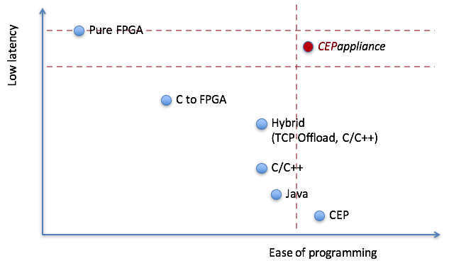
Due to the ability to describe trading strategies in a high-level language, programming CEPappliance is easier than programming FPGA directly in hardware description languages (Verilog, VHDL, etc.) with comparable delays. Programming a trading strategy with CEPappliance is as simple as launching the same strategy using C / C ++, Java, etc. due to the presence in CEPappliance of ready-made message assembling / disassembling blocks in accordance with protocols, a “glass” assembly, etc., and a single-threaded programming model (although at the firmware level, execution can be parallel, as mentioned earlier) with less latency and jitter ) The positioning of the CEPappliance with respect to other technologies used in the HFT in the coordinates “ease of programming” and “delay” is depicted in the following diagram:
To approximate the speed of CEPappliance to the speed of a solution that is fully implemented in FPGA, any part of the circuit can be implemented directly on Verilog. There is an operator for this(see below). At the same time, parts less critical to speed (for example, managing a trading robot, monitoring) can be left on the HLL. This approach allows you to get the maximum speed of the trading robot with significant savings in development efforts.
Scheme (program) of the HFT strategy
Here is an example of a scheme that, after receiving the USD000UTSTOM “glass” update, which is built on data from the order stream (X-OLR-CURR messages) of the Moscow Exchange currency section, sends an application for purchase at the best selling price to the exchange:
Example Schema for CEPappliance
The scheme for CEPappliance is a set of operators that convert the input streams of events received through adapters from external systems to the output streams of events transmitted through adapters to external systems.
An event in a schema is a collection of fields. Each field has a name and type. Events have the same structure if they have the same set of fields, namely the number, order, names and types of fields are the same.
The scheme consists of several sections:
describes the adapters through which the circuit receives / sends data; adapters available, , , . It only works on receiving FAST messages on UDP datagrams. and work on receiving and / or sending TCP messages FIX and TWIME (FIX Simple Binary Encoding), respectively. It can work both for receiving and sending via TCP or UDP and is used, as a rule, to control the work of a trading strategy - requesting a status, setting parameters, etc. Description of adapters can be made in a separate file. Then you can run the same scheme with adapters configured for different environments. For example, for a test environment, you can have one adapter configuration, and for a “combat” environment, you can have another adapter configuration.
describes financial instruments types constants and (global) variables available in any other section of the circuit.
,
Event processing in the CEPappliance can be conceptually described as follows. After receiving an event from an external system, the adapter searchesthrough which the event should be passed to the circuit. To do this, filter conditions are checked. each connected to this adapter. If an event does not satisfy any such condition, then it is discarded and is not processed in any way. If suitable found, then the event is passed to the operators for which this is the input. In this case, only those fields that are declared in. The remaining fields of the event are discarded and not transmitted to the scheme.
Having received one event at the input, each operator of the circuit generates another (one or several, such as) an event whose set and field values may differ from the input. OnlyIt does not generate new events, but transmits what it received at the input without changes.
“Walking” according to the scheme, transforming more than once, and, perhaps, “multiplying” and “reaching”