Uploaded USB Mass Storage Device to STM32F103 using FreeRTOS and DMA

Recently, I was tinkering with connecting my device to the STM32F103 microcontroller as a USB Mass Storage Device , or in Russian as a USB flash drive. Everything seems to be relatively simple: in the graphical configurator STM32CubeMX, a couple of clicks generated the code, added the SD card driver, and voila - everything works. Only very slowly - 200 kB / s despite the fact that the bandwidth of the USB bus in Full Speed mode is much higher - 12 mB / s (roughly 1.2 MB / s). Moreover, the start time of my flash drive in the operating system is about 50 seconds, which is simply uncomfortable in work. Since I dived into this area, why not fix the transmission speed.
Actually, I already wrote my driver for the SD card(more precisely, the SPI driver), which worked through DMA and provided speeds of up to 500 kb / s. Unfortunately, in the context of USB, this driver did not work. The reason for this is the USB communication model itself - everything is done on interrupts, while my driver was tuned to work in a normal stream. Yes, and powdered primitives synchronization FreeRTOS.
In this article, I made a couple of feints that made it possible to squeeze the maximum out of a bunch of USB and SD cards connected to the STM32F103 microcontroller via SPI. It will also be about FreeRTOS, synchronization objects, and general approaches to transferring data through DMA. So, I think this article will be useful to those who are only versed in STM32 controllers, and tools like DMA, and approaches when working with FreeRTOS. The code is based on the HAL and USB Middleware libraries from the STM32Cube package, as well as SdFat for working with an SD card.
Architecture Overview
If you do not go into the details of the individual components, then the implementation of the Mass Storage Device (aka Mass Storage Class - MSC) on the side of the microcontroller is a relatively simple thing.

On the one hand is the USB Core library. She is engaged in communication with the host, provides registration of the device and implements all sorts of low-level pieces of USB.
The Mass Storage driver (using the USB kernel) can receive and send data to the host. Like a COM port, only data is transmitted in blocks. The semantic content of this data is important here: SCSI commands and data are transmitted to them. Moreover, there are only a few types of commands that run: read data, write data, find out the size of the storage device, and find out the readiness of the device.
The task of the MSC driver is to interpret SCSI commands and redirect calls to the storage driver. It can be any storage device with block access (RAM disk, flash drive, network storage, CD, etc.). In my case, the storage device is a microSD card connected via SPI. The set of functions that are required from the driver is approximately the same: read, write, give size and ready state.
And here one important nuance appears, because of which the whole fuss is actually. The fact is that the USB protocol is host-oriented. Only a host can start transactions, send or receive data. From the point of view of the microcontroller, this means that all activity associated with USB will take place in the context of an interrupt. In this case, the corresponding handler will be called on the MSC driver.
As for sending data from the microcontroller towards the host. The microcontroller cannot initiate data transfer on its own. The maximum that the microcontroller can signal to the USB core is that there is data that the host can pick up.
With the SD card itself, it is also not so simple. The fact is that the card is a complex device (apparently it has its own microcontroller), and the communication protocol is very non-trivial. Those. it didn’t just send / receive data to a specific address (as is the case with some kind of I2C EEPROM module). The protocol for communicating with the card provides for a whole set of various commands and confirmations, checksums and any timeouts.
I am using the SdFat library. It implements working with an SD card at the FAT file system level, which I actively use in my device. In the case of a USB connection, everything connected with the file system is disconnected (this role is transferred to the host). But what’s important, the library separately allocates a card driver with an interface that is almost the same as the MSC driver wants - to read, write, find out the size.
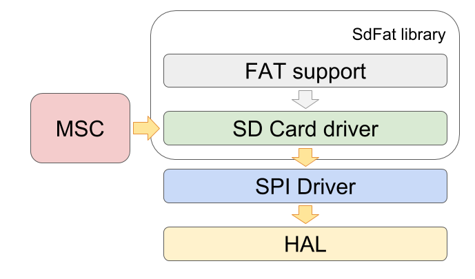
The card driver implements a protocol for communicating with the card through SPI. He knows exactly which commands to send to the map, in what sequence and which to wait for answers. But the driver itself does not deal with iron. For this, one more level of abstraction is provided - the SPI driver, which translates the read / write requests of individual blocks into the actual data transfer via the SPI bus. It was in this place that I was able to organize the transfer of data via DMA, which increased the data transfer speed in normal mode, but broke all the raspberries in the case of USB (DMA eventually had to be disabled)
But first things first.
What problem do we solve?
My colleague often asks this question, which puzzles the interlocutors during technical disputes.
There are 2 problems with all this kitchen:
- Low linear speed when working from under USB. Mainly due to and the use of synchronous read / write operations
- High processor load (up to 100%) - the device becomes impossible to use. The reason is the disabled DMA and the need to drive data using the processor.
But this is from the controller side, and there are still aspects of the USB Mass Storage protocol. I installed the USB wireshark sniffer and looked at exactly which packets are running on the bus and I see at least 3 more reasons for the low speed
- The host sends too many transactions
- Transactions stretched over time
- The read / write operations themselves occur synchronously, waiting for the end
The problem of the number of transactions is quite simple to solve. It turned out that when I connected my device, the OS reads the entire FAT table and does many more different small readings of the directory and MBR. I have a flash drive of 8 gigs, formatted in FAT32 with a cluster size of 4kb. It turns out that the FAT table takes about 8 MB. With a linear transmission speed of 200 kb / s, it turns out almost 40 seconds.
The easiest way to reduce the number of read operations when connecting a device is to reduce the FAT table. It is enough just to reformat the USB flash drive and increase the cluster size (thereby reducing their number and table size). I formatted the card by setting the cluster size to 16k - the FAT table size became slightly less than 2 MB, and the initialization time was reduced to 20 seconds.
More is not always better
I realized that for my device an 8 gig flash drive is too much, I don’t need so much. 1 gig, or even 512 megabytes, is quite enough. Just at hand there is no such flash drive yet. Moreover, they are not on sale even now. We'll have to scrape over the gimbal. As I find - I’ll try.
In any case, reformatting the flash drive does not solve the linear speed problem (the speed with which large files are read sequentially). It still remains at 200kb / s and loads the processor for the most I do not want. Let's see what we can do about it.
What is wrong with USB DMA?
Finally, let's
move on to the code and see how my read / write on the flash card (SPI driver) is arranged. In my project I use FreeRTOS. This is just an awesome tool that allowed me to process each function of my device in a separate thread (task). I managed to throw huge state machines for all occasions, and the code has become much simpler and more understandable. All tasks work simultaneously, yielding to each other and synchronizing if necessary. Well, if all the threads fell asleep in anticipation of some event, then you can use the power-saving modes of the microcontroller.
Code that works with an SD card also works in a separate thread. This made it possible to write read / write functions very elegantly.
SPI driver for reading / writing data to an SD card using DMA
uint8_t SdFatSPIDriver::receive(uint8_t* buf, size_t n)
{
    	// Start data transfer
    	memset(buf, 0xff, n);
    	HAL_SPI_TransmitReceive_DMA(&spiHandle, buf, buf, n);
    	// Wait until transfer is completed
    	xSemaphoreTake(xSema, 100);
    	return 0; // Ok status
}
void SdFatSPIDriver::send(const uint8_t* buf, size_t n)
{
    	// Start data transfer
    	HAL_SPI_Transmit_DMA(&spiHandle, (uint8_t*)buf, n);
    	// Wait until transfer is completed
    	xSemaphoreTake(xSema, 100);
}
void SdFatSPIDriver::dmaTransferCompletedCB()
{
    	// Resume SD thread
    	xSemaphoreGiveFromISR(xSema, NULL);
}
The whole charm here is that when we need to read or write a large block of data, this code does not wait for completion. Instead, data transfer via DMA starts, and the stream falls asleep. In this case, the processor can go about its business, and the transfer of control passes to other threads. When the transfer is completed, an interrupt from DMA will be called and the stream that was waiting for the data to be transferred will wake up.
Who is there?
The problem is that such an approach is difficult to pull on the USB model where all the logic of work occurs in interrupts, and not in the usual thread of execution. Those. it turns out that we will receive a read / write request in the interrupt, and the completion of data transfer will also have to wait in the same interrupt.
Of course, we will be able to arrange forwarding via DMA in the context of interruption, but there will be little sense from this. DMA works well where you can start the transfer and switch the processor to some other useful work until the data transfer is over. But starting the transfer from the interrupt, we will not be able to interrupt the interrupt (sorry for the tautology) and go about our business. Have to hang there and wait for the end of the transfer. Those. the operation will be synchronous and the total time will be the same as in the case without DMA.
Here it would be much more interesting, at the request of the host, to start transmitting data via DMA and exit the interrupt. And then somehow at the next interruption report on the work done.
But this is not the whole picture. If reading from the card consisted only in sending a data block, then this approach would not be difficult to implement. But SPI transmission is by far the most important part, but not the only one. If you look at reading / writing a data block at the level of the card driver, the process looks something like this.
- Send a command to the card, wait and check the response
- Wait until the card is ready
- Forward data (here is the very function that I cited above)
- Calculate the checksum and compare it with the opinion of the card
- Complete transfer
Given that this seemingly linear algorithm is implemented by a series of nested function calls, cutting it in the middle will not be very reasonable. We'll have to properly grind the entire library. And if we take into account that in some cases the transfer can be carried out not in one piece but in a cycle with a series of small blocks, then the task becomes completely impossible.
But it is not all that bad. If you look even higher - at the level of the MSC driver - then he will generally see how exactly the data will be transmitted - one block or several, with or without DMA. The main thing is to transmit data and report on the status.
An ideal place to experiment would be the layer between the MSC driver and the card driver. Before all the bullying, this component looked very trivial - in fact, it is an adapter between an interface that wants to see the MSC driver and what the card driver gives out.
Original adapter implementation
int8_t SD_MSC_Read (uint8_t lun,
						uint8_t *buf,
						uint32_t blk_addr,
						uint16_t blk_len)
{
	(void)lun; // Not used
	if(!card.readBlocks(blk_addr, buf, blk_len))
		return USBD_FAIL;
	return (USBD_OK);
}
int8_t SD_MSC_Write (uint8_t lun,
						 uint8_t *buf,
						 uint32_t blk_addr,
						 uint16_t blk_len)
{
	(void)lun; // Not used
	if(!card.writeBlocks(blk_addr, buf, blk_len))
		return USBD_FAIL;
	return (USBD_OK);
}
As I said, the card driver does not work if it is called from under an interrupt. But it works well in a normal thread. So, let's start a separate thread for it.
This thread will receive read and write requests through the queue. Each request includes information about the type of operation (read / write), the number of the block to be read or written, the number of blocks and a pointer to the data buffer. I also got a pointer to the context of the operation - we will need it a little later.
Read / Write Request Queue
enum IOOperation
{
	IO_Read,
	IO_Write
};
struct IOMsg
{
	IOOperation op;
	uint32_t lba;
	uint8_t * buf;
	uint16_t len;
	void * context;
};
// A queue of IO commands to execute in a separate thread
QueueHandle_t sdCmdQueue = NULL;
// Initialize thread responsible for communication with SD card
bool initSDIOThread()
{
	// Initialize synchronisation
	sdCmdQueue = xQueueCreate(1, sizeof(IOMsg));
	bool res = card.begin(&spiDriver, PA4, SPI_FULL_SPEED);
	return res;
}
The thread itself is sleeping waiting for commands. If a command arrives, then the desired operation is performed, moreover, synchronously. At the end of the operation, we call the callback, which, depending on the implementation, will do what is needed at the end of the read / write operation.
Stream serving reading / writing to a card
extern "C" void cardReadCompletedCB(uint8_t res, void * context);
extern "C" void cardWriteCompletedCB(uint8_t res, void * context);
void xSDIOThread(void *pvParameters)
{
    while(true)
    {
        IOMsg msg;
        if(xQueueReceive(sdCmdQueue, &msg, portMAX_DELAY))
        {
            switch(msg.op)
            {
                case IO_Read:
                {
                    bool res = card.readBlocks(msg.lba, msg.buf, msg.len);
                    cardReadCompletedCB(res ? 0 : 0xff, msg.context);
                    break;
                }
                case IO_Write:
                {
                    bool res = card.writeBlocks(msg.lba, msg.buf, msg.len);
                    cardWriteCompletedCB(res? 0 : 0xff, msg.context);
                    break;
                }
                default:
                    break;
            }
        }
    }
}
Since all this is performed as part of a normal flow, the card driver inside can use DMA and FreeRTOS synchronization.
MSC functions have become a little more complicated, but not by much. Now, instead of directly reading or writing, this code sends a request to the corresponding stream.
Sending read / write requests
int8_t SD_MSC_Read (uint8_t lun,
					uint8_t *buf,
					uint32_t blk_addr,
					uint16_t blk_len,
					void * context)
{
	// Send read command to IO executor thread
	IOMsg msg;
	msg.op = IO_Read;
	msg.lba = blk_addr;
	msg.len = blk_len;
	msg.buf = buf;
	msg.context = context;
	if(xQueueSendFromISR(sdCmdQueue, &msg, NULL) != pdPASS)
		return USBD_FAIL;
	return (USBD_OK);
}
int8_t SD_MSC_Write (uint8_t lun,
					 uint8_t *buf,
					 uint32_t blk_addr,
					 uint16_t blk_len,
					 void * context)
{
	// Send read command to IO executor thread
	IOMsg msg;
	msg.op = IO_Write;
	msg.lba = blk_addr;
	msg.len = blk_len;
	msg.buf = buf;
	msg.context = context;
	if(xQueueSendFromISR(sdCmdQueue, &msg, NULL) != pdPASS)
		return USBD_FAIL;
	return (USBD_OK);
}
There is an important point - the semantics of these functions has changed. Now they are asynchronous, i.e. Do not wait for the real end of the operation. So it will be necessary to tweak the code that calls them, but we will deal with this a bit later.
In the meantime, to test these functions, we will make another test thread. It will emulate a USB core and send read requests.
Test stream
uint8_t io_buf[1024];
static TaskHandle_t xTestTask = NULL;
void cardReadCompletedCB(bool res, void * context)
{
	xTaskNotifyGive(xTestTask);
}
void cardWriteCompletedCB(bool res, void * context)
{
	xTaskNotifyGive(xTestTask);
}
void xSDTestThread(void *pvParameters)
{
	xTestTask = xTaskGetCurrentTaskHandle();
	uint32_t prev = HAL_GetTick();
	uint32_t opsPer1s = 0;
	uint32_t cardSize = card.cardSize();
	for(uint32_t i=0; i 1000)
		{
			prev = HAL_GetTick();
			usbDebugWrite("Reading speed: %d kbytes/s\r\n", opsPer1s);
			opsPer1s = 0;
		}
	}
	while(true)
		;
}
This code reads the entire card from beginning to end in blocks of 1kb and measures the reading speed. Each read operation sends a request to the SD card stream. There, synchronously, reading takes place and reports the end via a callback. I substituted my implementation of this callback, which simply signals to the test thread that it can continue (the test thread has been sleeping all this time in the ulTaskNotifyTake () function).
But most importantly, the read speed in this version is about 450 kb / s, and the processor is only 3-4% loaded. In my opinion, not bad.
We pump the driver MSC
So, we won the card driver by enabling DMA. But the semantics of read / write has changed from synchronous to asynchronous. Now you need to tweak the implementation of MSC and teach it how to work with asynchronous calls. Those. we need to start the transfer through the DMA to the first request from the host, and somehow respond to all subsequent ones, saying, “the previous operation has not yet ended, check back later”.
In fact, the USB protocol provides such a mechanism right out of the box . The receiving side confirms the transfer of data by a certain status. If the data is received and processed successfully, then the receiver confirms the transaction with ACK status. If the device cannot process the transaction (not initialized, is in an error state or does not work for any other reason), the response will be the status STALL.
But if the device recognized the transaction, is in a healthy state, but the data is not ready yet, then the device can respond NAK. In this case, the host must contact the device with the exact same request a bit later. We could use this status for deferred read / write - on the first call to the host, we start transmitting data through DMA, but respond to transaction NAK. When the host arrives with a repeat transaction and the transfer through DMA is already over, we respond with the ACK.
Unfortunately, I did not find a good way to send a NAK signal in the USB library from ST. Function return codes are either not checked, or they can process only 2 states - everything is fine, or an error. In the second case, all endpoints are closed, the status STALL is set everywhere.
I suspect that at the lowest level of the USB driver, NAK confirmation is used quite actively, but I did not figure out how to properly stick with NAK at the class driver level.
Apparently, the creators of the libraries from ST, instead of various confirmations, provided a more humane interface. If the device has something to send to the host, it calls the USBD_LL_Transmit () function - the host itself will pick up the provided data. And if the function was not called, the device will automatically respond with NAK answers. Approximately the same situation with receiving data. If the device is ready to receive, it calls the USBD_LL_PrepareReceive () function. Otherwise, the device will respond NAK if the host attempts to transmit data. We will use this knowledge to implement our MSC driver.
Let's see what transactions run on the USB bus (analysis was performed before the changes in the card driver).
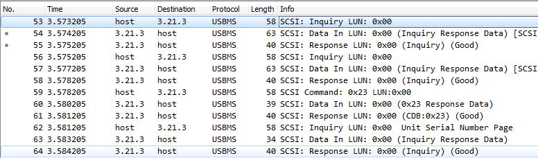
It is not even the transactions themselves that are interesting here, but their timestamps. The transactions in this picture, I chose "light" - those that do not require processing. The microcontroller responds to such requests with hard-coded answers, without much thought. The important thing here is that the host does not send transactions in a continuous stream. Transactions go no more than once every 1 ms. Even if the answer is ready immediately, the host will pick it up only on the next transaction in 1ms.
And this is how reading one block of data looks like in terms of transactions on the USB bus.

First, the host sends the SCSI read command, and then reads the data (second line) and status (third) in separate transactions. The first transaction is the longest. During the processing of this transaction, the microcontroller is engaged in the deduction from the card. And, again, between transactions, the host pauses for 1ms.
By the way.
In USB terminology, the direction from the host to the device is called OUT, although for the controller this is a technique. Conversely, the direction from the device to the host is called IN, although for us this means sending data.
The MSC driver algorithm on the microcontroller side looks something like this
- SCSI Transaction: Read (10) LUN: 0x00 (LBA: 0x00000000, Len: 1)
- The host sends a read command. The function MSC_BOT_DataOut () is called from the microcontroller
- The command is processed by the chain of functions MSC_BOT_DataOut () -> MSC_BOT_CBW_Decode () -> SCSI_ProcessCmd () -> SCSI_Read10 ()
- Since the driver is in the state hmsc-> bot_state == USBD_BOT_IDLE, the read procedure is being prepared: the command parameters are checked, how many total blocks need to be read, and then control is transferred to the SCSI_ProcessRead () function with a request to read the first block
- The SCSI_ProcessRead () function reads data in synchronous mode. This is where the microcontroller is busy most of the time .
- When the data is received, it is transferred (using the USBD_LL_Transmit () function) to the output buffer of the endpoint MSC_IN, so that the host can pick it up
- The driver goes into the state hmsc-> bot_state = USBD_BOT_DATA_IN
- SCSI Transaction: Data In
- The host collects data from the output buffer of the microcontroller in packets of 64 bytes (the maximum recommended packet size for USB Full Speed devices). All this happens at the lowest level in the USB core, the MSC driver is not involved
- When the host has taken all the data, the Data In event is raised. Control is passed to the MSC_BOT_DataIn () function. I emphasize that this function is called after the actual sending of data.
- The driver is in the state hmsc-> bot_state == USBD_BOT_DATA_IN, which means we are still in read mode.
- If not all the ordered blocks have been read yet, we start reading the next piece and wait for the completion , transfer it to the output buffer and wait until the host picks up the data. Algorithm repeats
- If all blocks are read, the driver switches to USBD_BOT_LAST_DATA_IN to send the final status of the command
- SCSI Transaction: Response
- At this point, the parcel data has already been sent.
- the driver only receives a notification about this and goes into the USBD_BOT_IDLE state
The longest operation in this scheme is actually reading from the card. According to my measurements, reading takes about 2-3ms in synchronous mode. Moreover, the transfer occurs by means of the processor and all this happens in the interrupt USB. For comparison, subtracting one block of 512 in length via DMA takes a little more than 1ms.
I couldn’t significantly (say up to 1Mb / s) speed up data reading - apparently this is the bandwidth of the card connected via SPI. But we can try putting at our service 1ms pauses between transactions.
I see it like this (slightly simplified)
- SCSI Transaction: Read (10) LUN: 0x00 (LBA: 0x00000000, Len: 1)
- The microcontroller receives a read command, checks all the parameters, remembers the number of blocks that need to be read
- The microcontroller starts reading the first block in asynchronous mode
- Exit interruption without waiting for the end of reading
- When the reading is finished, the callback is called
- Read data is sent to the output buffer.
- The host reads them without the MSC driver
- SCSI Transaction: Data In
- The callback function DataIn () is called, which signals that the host has taken the data and you can do the next reading
- We start reading the next block. The algorithm is repeated starting with the read completion callback
- If all blocks are read - send a status packet
- SCSI Transaction: Response
- At this point, the parcel data has already been sent.
- Getting ready for the next transaction.
Let's try to implement this approach, since the SCSI_ProcessRead () function is easily divided into “before” and “after”. That is, the code that starts reading will be executed in the context of the interrupt, and the remaining code will be moved to the callback. The task of this callback is to push the read data into the output buffer (the host will then somehow pick up this data with the corresponding requests)
SCSI_ProcessRead () function adapted for asynchronous reading
/**
* @brief  SCSI_ProcessRead
*         Handle Read Process
* @param  lun: Logical unit number
* @retval status
*/
static int8_t SCSI_ProcessRead (USBD_HandleTypeDef  *pdev, uint8_t lun)
{
	USBD_MSC_BOT_HandleTypeDef  *hmsc = pdev->pClassDataMSC;
	uint32_t len;
	len = MIN(hmsc->scsi_blk_len , MSC_MEDIA_PACKET);
	if( pdev->pClassSpecificInterfaceMSC->Read(lun ,
						hmsc->bot_data,
						hmsc->scsi_blk_addr / hmsc->scsi_blk_size,
						len / hmsc->scsi_blk_size,
						pdev) < 0)
	{
		SCSI_SenseCode(pdev,
				lun,
				HARDWARE_ERROR,
				UNRECOVERED_READ_ERROR);
		return -1;
	}
	hmsc->bot_state = USBD_BOT_DATA_IN;
	return 0;
}
void cardReadCompletedCB(uint8_t res, void * context)
{
	USBD_HandleTypeDef * pdev = (USBD_HandleTypeDef *)context;
	USBD_MSC_BOT_HandleTypeDef  *hmsc = pdev->pClassDataMSC;
	uint8_t lun = hmsc->cbw.bLUN;
	uint32_t len = MIN(hmsc->scsi_blk_len , MSC_MEDIA_PACKET);
	if(res != 0)
	{
		SCSI_SenseCode(pdev,
				lun,
				HARDWARE_ERROR,
				UNRECOVERED_READ_ERROR);
		return;
	}
	USBD_LL_Transmit (pdev,
				MSC_IN_EP,
				hmsc->bot_data,
				len);
	hmsc->scsi_blk_addr   += len;
	hmsc->scsi_blk_len    -= len;
	/* case 6 : Hi = Di */
	hmsc->csw.dDataResidue -= len;
	if (hmsc->scsi_blk_len == 0)
	{
		hmsc->bot_state = USBD_BOT_LAST_DATA_IN;
	}
}
In a callback, you need to access several variables that are defined in the SCSI_ProcessRead () function - a pointer to a USB handle, the length of the transmitted block, LUN. This is where the context parameter came in handy. True, I did not transmit everything, but only pdev, and everything else can be fished out of it. As for me, this approach is simpler than pulling the whole structure with the desired fields. And, in any case, this is better than having a few global variables.
Add a double buffer
The approach, in general, worked, but the speed was still a little more than 200kb / s (although the processor load was repaired and became about 2-3%). Let's figure out what prevents us from working faster.
On the advice in the comments to one of my articles, I still got an oscilloscope (albeit a cheap one). He was very helpful in understanding what was going on there. I took an unused pin and set it to one before reading and zero after reading ended. On the oscilloscope, the reading process looked like this.

Those. reading 512 bytes takes a little more than 1ms. When reading from the card ends, the data is transferred to the output buffer, from where the host picks them up over the next 1ms. Those. here either reading from the card or transferring via USB, but not simultaneously.
Typically, this situation is solved by double buffering. Moreover, the STM32F103 microcontroller USB peripherals already offer dual buffering mechanisms. Only they will not suit us for two reasons:
- To use the double buffering offered by the microcontroller itself, you may have to redraw the USB core and the implementation of MSC
- The buffer size is only 64 bytes, while an SD card cannot work with blocks of less than 512 bytes.
So we have to invent our own implementation. However, this should not be difficult. First, reserve a place for the second buffer. I did not start a separate variable for him, but simply increased the existing buffer by 2 times. I also had to set up the variable bot_data_idx, which will indicate which half of this double buffer is currently used: 0 - the first half, 1 - the second.
Double buffer
typedef struct _USBD_MSC_BOT_HandleTypeDef
{
...
 USBD_MSC_BOT_CBWTypeDef  cbw;
 USBD_MSC_BOT_CSWTypeDef  csw;
 uint16_t                 bot_data_length;
 uint8_t                  bot_data[2 * MSC_MEDIA_PACKET];
 uint8_t                  bot_data_idx;
...
}
USBD_MSC_BOT_HandleTypeDef;
By the way, the cbw and csw structures are very sensitive to alignment. Some values were incorrectly written or read from the fields of these structures. Therefore it was necessary to transfer them higher than data buffers.
The original implementation worked on a DataIn interrupt - a signal that the data was sent. Those. upon a command from the host, reading was started, after which the data was transferred to the output buffer. Reading the next batch of data was “recharged” by interrupting the DataIn. This option does not suit us. We will begin reading immediately after the previous reading has ended.
Recharge reading immediately after the previous one has ended
void cardReadCompletedCB(uint8_t res, void * context)
{
	USBD_HandleTypeDef * pdev = (USBD_HandleTypeDef *)context;
	USBD_MSC_BOT_HandleTypeDef  *hmsc = pdev->pClassDataMSC;
	uint8_t lun = hmsc->cbw.bLUN;
	uint32_t len = MIN(hmsc->scsi_blk_len , MSC_MEDIA_PACKET);
	if(res != 0)
	{
		SCSI_SenseCode(pdev,
					   lun,
					   HARDWARE_ERROR,
					   UNRECOVERED_READ_ERROR);
		return;
	}
	// Synchronization to avoid several transmits at a time
	// This must be located here as it waits finishing previous USB transfer
	// while the code below prepares next one
	pdev->pClassSpecificInterfaceMSC->OnFinishOp();
	// Save these values for transmitting data
	uint8_t * txBuf = hmsc->bot_data + hmsc->bot_data_idx * MSC_MEDIA_PACKET;
	uint16_t txSize = len;
	// But before transmitting set the correct state
	// Note: we are in context of SD thread, not the USB interrupt
	// So values have to be correct when DataIn interrupt occurrs
	hmsc->scsi_blk_addr   += len;
	hmsc->scsi_blk_len    -= len;
	/* case 6 : Hi = Di */
	hmsc->csw.dDataResidue -= len;
	if (hmsc->scsi_blk_len == 0)
	{
		hmsc->bot_state = USBD_BOT_LAST_DATA_IN;
	}
	else
	{
		hmsc->bot_data_idx ^= 1;
		hmsc->bot_data_length = MSC_MEDIA_PACKET;
		SCSI_ProcessRead(pdev, lun); // Not checking error code - SCSI_ProcessRead() already enters error state in case of read failure
	}
	// Now we can transmit data read from SD
	USBD_LL_Transmit (pdev,
					  MSC_IN_EP,
					  txBuf,
					  txSize);
}
This function has slightly changed the structure. Firstly, it is here that support for double buffering is implemented. Since this function is called when reading from the card is finished, we can immediately start the next reading by calling SCSI_ProcessRead (). So that a new reading does not erase the data that has just been read, just use the second buffer. The buffer_data_idx variable is responsible for switching buffers.
But that is not all. Secondly, the sequence of actions has changed. Now the reading of the next data block is charged first and only then USBD_LL_Transmit () is called. This is because the cardReadCompletedCB () function is called in the context of a regular thread. If you call USBD_LL_Transmit () at the beginning, and then change the values of the hmsc fields, then potentially at this moment an interrupt from USB can be caused, which also wants to change these fields.
Thirdly, I had to tighten the additional synchronization. The fact is that usually reading from a card takes a little longer than transferring via USB. But sometimes it’s the other way around, and then the USBD_LL_Transmit () call for the next block happens earlier than the previous block was completely sent. The USB core from such impudence fools and data is sent incorrectly.
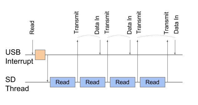
Sending data (Transmit) is confirmed by the Data In event, but sometimes several Transmites occur in a row. For such a case, you need synchronization.
This is solved very simply by adding a little synchronization. I added a couple of functions with a fairly simple implementation to the USBD_StorageTypeDef interface (although, perhaps, the names are not very successful). The implementation uses a regular semaphore in signal-wait mode . OnFinishOp (), which is called, in the callback cardReadCompletedCB () will sleep and wait until the previous data packet is sent.
The fact of sending is confirmed by the DataIn event, which is processed by the SCSI_Read10 () function, which will call OnStartOp (), which will unlock OnFinishOp (), which will send the next data packet
Implement synchronization features
void SD_MSC_OnStartOp()
{
	xSemaphoreGiveFromISR(usbTransmitSema, NULL);
}
void SD_MSC_OnFinishOp()
{
	xSemaphoreTake(usbTransmitSema, portMAX_DELAY);
}
With such synchronization, the picture takes the following form.
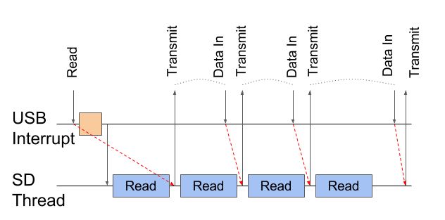
Red arrows indicate synchronization. The last Transmit is waiting for the previous Data In.
The last piece of the puzzle is the SCSI_Read10 () function.
SCSI_Read10 () function, which is called on the Data In event
/**
* @brief  SCSI_Read10
*         Process Read10 command
* @param  lun: Logical unit number
* @param  params: Command parameters
* @retval status
*/
static int8_t SCSI_Read10(USBD_HandleTypeDef  *pdev, uint8_t lun , uint8_t *params)
{
  USBD_MSC_BOT_HandleTypeDef  *hmsc = pdev->pClassDataMSC;
  // Synchronization to avoid several transmits at a time
  pdev->pClassSpecificInterfaceMSC->OnStartOp();
  if(hmsc->bot_state == USBD_BOT_IDLE)  /* Idle */
  {
    // Params checking
…
    hmsc->scsi_blk_addr = ...
    hmsc->scsi_blk_len = ...
    hmsc->bot_state = USBD_BOT_DATA_IN;
...
    hmsc->bot_data_idx = 0;
    hmsc->bot_data_length = MSC_MEDIA_PACKET;
    return SCSI_ProcessRead(pdev, lun);
  }
  return 0;
}
In the original implementation of SCSI_Read10 (), the parameters were checked on the first call to the function and the process of reading the first block was started. The same function is called later when DataIn is interrupted when the previous packet has already been sent and you need to start reading the next one. Both branches started reading using the SCSI_ProcessRead () function.
In the new implementation, the call to SCSI_ProcessRead () moved inside the if and is called only to read the first block (bot_state == USBD_BOT_IDLE), while reading subsequent blocks is started from cardReadCompletedCB ().
Let's see what came of it. I deliberately added slight delays between the readings of the blocks in order to see such notches on the oscilloscope. In fact, so little time passes between the read operations that my oscilloscope does not see this.
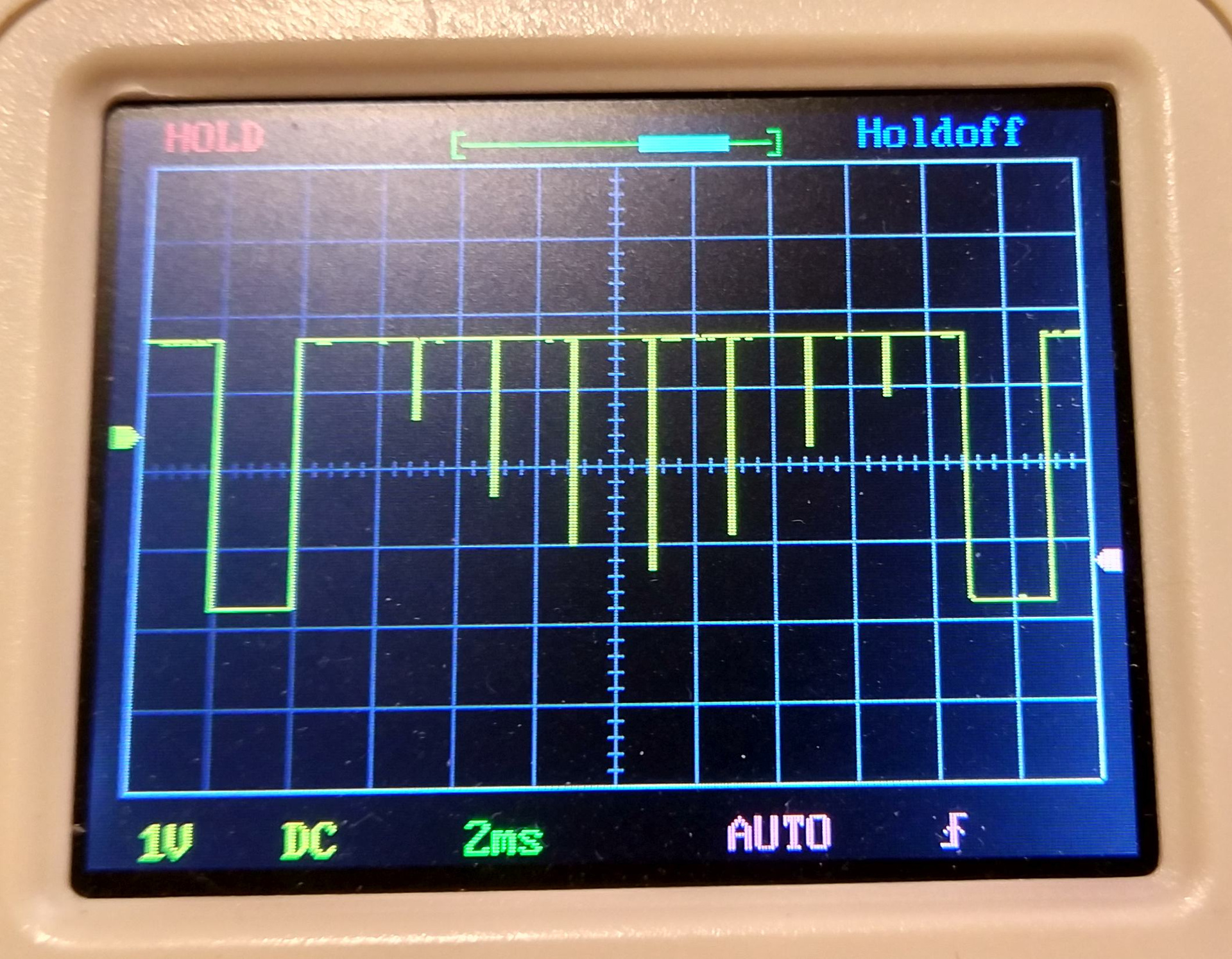
As you can see from this picture, the idea was a success. A new read operation starts as soon as the previous one has finished. The pauses between reads are quite small and are dictated mainly by the host (the same delay of 1ms between transactions). The average reading speed of large files reaches 400-440kb / s, which is very good. And finally, the processor load is about 2%.
But what about the record?
While I tactfully avoided the topic of recording on the card. But now, with the knowledge and understanding of the MSC driver, the implementation of the recording function does not have to be complicated.
The original implementation works something like this.
- SCSI Write Transaction
- The command is processed by the chain of functions MSC_BOT_DataOut () -> MSC_BOT_CBW_Decode () -> SCSI_ProcessCmd () -> SCSI_Write10 ()
- Поскольку драйвер находится в состоянии hmsc->bot_state == USBD_BOT_IDLE, то готовится процедура записи: проверяются параметры команды, запоминается сколько всего блоков нужно будет записать
- Вызывается функция USBD_LL_PrepareReceive() которая готовит периферию USB к приему блока данных.
- Драйвер переходит в состояние hmsc->bot_state = USBD_BOT_DATA_OUT
- Транзакция SCSI: Data Out
- Устройство принимает данные пакетами по 64 байта и укладывает эти данные в предоставленный буфер. Все это происходит на самом низком уровне в ядре USB, драйвер MSC в этом не участвует
- Когда данные приняты возникает событие Data Out и опять вызывается функция SCSI_Write10()
- Поскольку драйвер находится в состоянии hmsc->bot_state == USBD_BOT_DATA_OUT, то управление переходит функции SCSI_ProcessWrite()
- Там происходит запись на карту в синхронном режиме
- If not all data has been received yet, then the reception is “recharged” by calling USBD_LL_PrepareReceive ()
- If all the blocks are written, the function MSC_BOT_SendCSW () is called which sends a confirmation to the host (Control Status Word - CSW), and the driver switches to USBD_BOT_IDLE
- SCSI Transaction: Response
- At this point, the status package has already been sent. No action required
First, we adapt the original implementation to the asynchrony of the Write () function. You just need to separate the SCSI_ProcessWrite () function and call the other half in the callback.
Record Function Implementation
/**
* @brief  SCSI_ProcessWrite
*         Handle Write Process
* @param  lun: Logical unit number
* @retval status
*/
static int8_t SCSI_ProcessWrite (USBD_HandleTypeDef  *pdev, uint8_t lun)
{
	uint32_t len;
	USBD_MSC_BOT_HandleTypeDef  *hmsc = pdev->pClassDataMSC;
	len = MIN(hmsc->scsi_blk_len , MSC_MEDIA_PACKET);
	if(pdev->pClassSpecificInterfaceMSC->Write(lun ,
						hmsc->bot_data,
						hmsc->scsi_blk_addr / hmsc->scsi_blk_size,
						len / hmsc->scsi_blk_size,
						pdev) < 0)
	{
		SCSI_SenseCode(pdev,
					   lun,
					   HARDWARE_ERROR,
					   WRITE_FAULT);
		return -1;
	}
	return 0;
}
 return 0;
}
void cardWriteCompletedCB(uint8_t res, void * context)
{
	USBD_HandleTypeDef * pdev = (USBD_HandleTypeDef *)context;
	USBD_MSC_BOT_HandleTypeDef  *hmsc = pdev->pClassDataMSC;
	uint8_t lun = hmsc->cbw.bLUN;
	uint32_t len = MIN(hmsc->scsi_blk_len , MSC_MEDIA_PACKET);
	// Check error code first
	if(res != 0)
	{
		SCSI_SenseCode(pdev,
				lun,
				HARDWARE_ERROR,
				WRITE_FAULT);
		return;
	}
	hmsc->scsi_blk_addr  += len;
	hmsc->scsi_blk_len   -= len;
	/* case 12 : Ho = Do */
	hmsc->csw.dDataResidue -= len;
	if (hmsc->scsi_blk_len == 0)
	{
		MSC_BOT_SendCSW (pdev, USBD_CSW_CMD_PASSED);
	}
	else
	{
		/* Prepare EP to Receive next packet */
		USBD_LL_PrepareReceive (pdev,
						MSC_OUT_EP,
						hmsc->bot_data,
						MIN (hmsc->scsi_blk_len, MSC_MEDIA_PACKET));
	}
}
Just as in the case of reading, you need to somehow deliver some variables from the first function to the second. And for this I use the context parameter and pass the handle of the USB device (from it you can fetch all the necessary data).
The recording speed in this mode is about 90 kb / s and is mainly limited by the speed of writing to the card. This is confirmed by the waveform - each peak is a record of one block. Judging by the picture, recording 512 bytes takes from 3 to 6ms (each time in a different way).
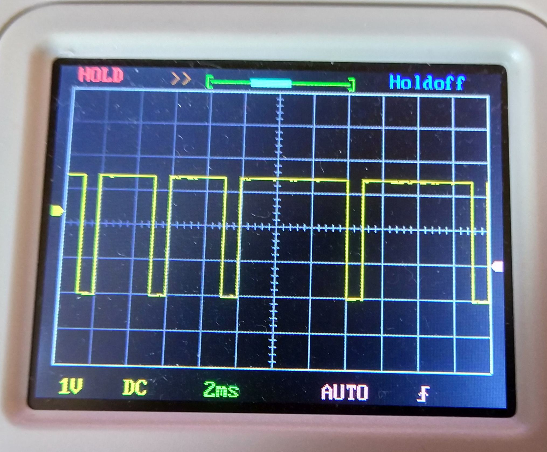
Moreover, a record can sometimes stick from 100ms to 0.5s - apparently somewhere in the map there is a need for various internal activities - remapping blocks, erasing pages, or something like that.
On this basis, the completion of a double buffer is unlikely to drastically improve the situation. However, anyway we’ll try to do this purely out of sports interest.
So, the essence of the exercise is to take the next block from the host while the previous one is written to the card. An option immediately comes to mind to start recording and receiving the next block simultaneously somewhere in the SCSI_Write10 () function, i.e. by the DataOut event (the reception of the next block is completed). Only nothing will work. because reception is much faster than recording and more data can be received than the card manages to write. Those. The following data is overwritten previously accepted, but not yet processed.

In this scheme, several packets can be received in a row, but not all of them will be recorded on the SD card. Most likely, part of the data will be erased by the next block.
Need to do synchronization. Only where? In the case of a read operation, we organized double buffering and synchronization in the place where reading from the card ends and the data is transferred to USB. This place was the cardReadCompletedCB () function. In the case of a write operation, the central place will be the SCSI_Write10 () function - it will be in it when the next data block is received, and it is from here that we will start writing to the card.
But there is one fundamental difference between the cardReadCompletedCB () and SCSI_Write10 () functions - the first works in the SD card stream, and the second in USB interrupt. A regular thread may be suspended while waiting for some event or synchronization object. Such an interruption will not work with interruption - all FreeRTOS functions with the FromISR suffix are non-blocking. They either work as they should (they capture the resource if it is free, send / receive messages through the queue if there is space or the necessary message), or these functions return an error. But they never wait.
But if it is impossible to organize a wait in an interrupt, then you can try to make sure that the interrupt is not called again at all. More precisely, even this: that the interruption occurs exactly as many times and at such moments when we need to.
Let's look at a few cases that may arise during the reception / recording process.
Case No. 1: reception of the first block. As soon as the first block is received, you can start recording this block. At the same time, you can start receiving the second block. This will save a pause when we do not accept the next block while the previous one is written to the card.
Case No. 2: receiving a block in the middle of a transaction. Most likely both buffers will already be full. Somewhere in the SD card stream, a data block is being written from the first block, while the second block we just received from the host. In principle, nothing prevents you from charging the record of the second block - there is a queue at the input (see the SD_MSC_Read () function above), which regulates input requests and will write blocks in turn. You just need to make sure that in this queue there is a place for 2 requests.
But how to regulate the reception? We have only 2 receive buffers. If immediately after receiving the second block, you begin to receive the next one, then this will overwrite the data in the first buffer, from where the recording is currently going on to the card. In this case, it will be more correct to start receiving the next data block when the buffer is freed - when the recording ends (i.e. in the callback of the write function).
Finally, case number 3: you need to be able to correctly complete the reception / recording procedure. Everything is clear with the last block - instead of receiving the next block, you need to send to the CSW host that the data has been received and the transaction can be closed. But you need to remember that at the beginning of the transaction we already organized an extra reception, so the penultimate block should not order an extra block.
Here is a picture that describes these cases.
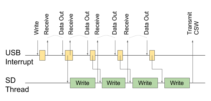
Case 1: on the first DataOut, we immediately begin receiving the second block. Case 2: we start receiving the next block only after the recording is finished and the buffer is free. Case 3: we don’t start reception on the penultimate record, we send CSW on the last
record. An interesting observation: if the record to the card comes from the first buffer, then at the end of the recording the next block will be received in the same first buffer. Similarly, with the second buffer. I would like to use this fact in my implementation.
Let's try to implement our plan. To implement the first case (receiving an additional block) we need a special state
New state for receiving the first block
#define USBD_BOT_DATA_OUT_1ST 6 /* Data Out state for the first receiving block */
And its processing
/**
* @brief  MSC_BOT_DataOut
*         Process MSC OUT data
* @param  pdev: device instance
* @param  epnum: endpoint index
* @retval None
*/
void MSC_BOT_DataOut (USBD_HandleTypeDef  *pdev,
					  uint8_t epnum)
{
	USBD_MSC_BOT_HandleTypeDef  *hmsc = pdev->pClassDataMSC;
	switch (hmsc->bot_state)
	{
	case USBD_BOT_IDLE:
		MSC_BOT_CBW_Decode(pdev);
		break;
	case USBD_BOT_DATA_OUT:
	case USBD_BOT_DATA_OUT_1ST:
		if(SCSI_ProcessCmd(pdev,
						   hmsc->cbw.bLUN,
						   &hmsc->cbw.CB[0]) < 0)
		{
			MSC_BOT_SendCSW (pdev, USBD_CSW_CMD_FAILED);
		}
		break;
	default:
		break;
	}
}
To implement the second case (receiving a block at the end of recording), you need to somehow transfer a certain amount of information to the callback. To do this, I created a structure with a recording context, and declared 2 instances of this structure in a USB handle.
Record Context
typedef struct
{
uint32_t                 next_write_len;
	uint8_t *                buf;
	USBD_HandleTypeDef *     pdev;
} USBD_WriteBlockContext;
typedef struct _USBD_MSC_BOT_HandleTypeDef
{
…
USBD_WriteBlockContext   write_ctxt[2];
...
}
USBD_MSC_BOT_HandleTypeDef;
You must remember to change the size of the recording queue in the SD card stream
Queue initialization
// Initialize thread responsible for communication with SD card
bool initSDIOThread()
{
	// Initialize synchronisation
	sdCmdQueue = xQueueCreate(2, sizeof(IOMsg));
…
}
The SCSI_Write10 () function has changed little, only the initialization of the double buffer index has been added and the transition to the USBD_BOT_DATA_OUT_1ST state
SCSI_Write10 () function
/**
* @brief  SCSI_Write10
*         Process Write10 command
* @param  lun: Logical unit number
* @param  params: Command parameters
* @retval status
*/
static int8_t SCSI_Write10 (USBD_HandleTypeDef  *pdev, uint8_t lun , uint8_t *params)
{
	USBD_MSC_BOT_HandleTypeDef  *hmsc = pdev->pClassDataMSC;
	if (hmsc->bot_state == USBD_BOT_IDLE) /* Idle */
	{
		// Checking params
		…
		hmsc->scsi_blk_addr = ...
		hmsc->scsi_blk_len  = ...
		/* Prepare EP to receive first data packet */
		hmsc->bot_state = USBD_BOT_DATA_OUT_1ST;
		hmsc->bot_data_idx = 0;
		USBD_LL_PrepareReceive (pdev,
						MSC_OUT_EP,
						hmsc->bot_data,
						MIN (hmsc->scsi_blk_len, MSC_MEDIA_PACKET));
	}
	else /* Write Process ongoing */
	{
		return SCSI_ProcessWrite(pdev, lun);
	}
	return 0;
}
All the most interesting logic will be concentrated in the SCSI_ProcessWrite () function - this is where buffers will be allocated and the entire chain of reads and records will be built.
SCSI_ProcessWrite () Function
/**
* @brief  SCSI_ProcessWrite
*         Handle Write Process
* @param  lun: Logical unit number
* @retval status
*/
static int8_t SCSI_ProcessWrite (USBD_HandleTypeDef  *pdev, uint8_t lun)
{
	USBD_MSC_BOT_HandleTypeDef  *hmsc = pdev->pClassDataMSC;
uint32_t len = MIN(hmsc->scsi_blk_len , MSC_MEDIA_PACKET);
	USBD_WriteBlockContext * ctxt = hmsc->write_ctxt + hmsc->bot_data_idx;
	// Figure out what to do after writing the block
	if(hmsc->scsi_blk_len == len)
	{
		ctxt->next_write_len = 0xffffffff;
	}
	else if(hmsc->scsi_blk_len == len + MSC_MEDIA_PACKET)
	{
		ctxt->next_write_len = 0;
	}
	else
	{
		ctxt->next_write_len = MIN(hmsc->scsi_blk_len - 2 * MSC_MEDIA_PACKET, MSC_MEDIA_PACKET);
	}
	// Prepare other fields of the context
	ctxt->buf = hmsc->bot_data + hmsc->bot_data_idx * MSC_MEDIA_PACKET;
	ctxt->pdev = pdev;
	// Do not allow several receives at a time
	if(hmsc->bot_state != USBD_BOT_DATA_OUT_1ST)
		pdev->pClassSpecificInterfaceMSC->OnStartOp();
	// Write received data
	if(pdev->pClassSpecificInterfaceMSC->Write(lun ,
							ctxt->buf,
							hmsc->scsi_blk_addr / hmsc->scsi_blk_size,
							len / hmsc->scsi_blk_size,
							ctxt) < 0)
	{
		SCSI_SenseCode(pdev,
					   lun,
					   HARDWARE_ERROR,
					   WRITE_FAULT);
		return -1;
	}
	// Switching blocks
	hmsc->bot_data_idx ^= 1;
	hmsc->scsi_blk_addr  += len;
	hmsc->scsi_blk_len   -= len;
	/* case 12 : Ho = Do */
	hmsc->csw.dDataResidue -= len;
	// Performing one extra receive for the first time in order to run receive and write operations in parallel
	if(hmsc->bot_state == USBD_BOT_DATA_OUT_1ST && hmsc->scsi_blk_len != 0)
	{
		hmsc->bot_state = USBD_BOT_DATA_OUT;
		USBD_LL_PrepareReceive (pdev,
						MSC_OUT_EP,
						hmsc->bot_data + hmsc->bot_data_idx * MSC_MEDIA_PACKET, // Second buffer
						MIN (hmsc->scsi_blk_len, MSC_MEDIA_PACKET));
	}
	return 0;
}
Firstly, the recording context is being prepared here - information that will be transmitted to the callback. In particular, it decides what we will do when the recording of this block ends:
- in the usual case, we will start receiving the next block into the same buffer (case No. 2 from the ones described above)
- In the case of the penultimate block, we will not do anything (case No. 3)
- In the case of the last block, we will send Control Status Word (CSW) - a report to the host about the status of the operation
After the data block has been sent to the write queue on the card, the buffer index (bot_data_idx) switches to the alternative one. Those. The next packet will be received in another buffer.
Finally, a special case (case No. 1) - we will organize additional data reception in the case of the first block (USBD_BOT_DATA_OUT_1ST state).
The response part of this code is the callback on completion of recording to the card. Depending on which block was recorded, either the reception of the next block is organized, either the CSW is sent, or nothing happens.
Callback recording function
void cardWriteCompletedCB(uint8_t res, void * context)
{
	USBD_WriteBlockContext * ctxt = (USBD_WriteBlockContext*)context;
	USBD_HandleTypeDef * pdev = ctxt->pdev;
	USBD_MSC_BOT_HandleTypeDef  *hmsc = pdev->pClassDataMSC;
	uint8_t lun = hmsc->cbw.bLUN;
	// Check error code first
	if(res != 0)
	{
		SCSI_SenseCode(pdev,
					   lun,
					   HARDWARE_ERROR,
					   WRITE_FAULT);
		return;
	}
	if (ctxt->next_write_len == 0xffffffff)
	{
		MSC_BOT_SendCSW (pdev, USBD_CSW_CMD_PASSED);
	}
	else
	{
		pdev->pClassSpecificInterfaceMSC->OnFinishOp();
		if(ctxt->next_write_len != 0)
		{
			/* Prepare EP to Receive next packet */
			USBD_LL_PrepareReceive (pdev,
							MSC_OUT_EP,
							ctxt->buf,
							ctxt->next_write_len);
		}
	}
}
The final chord is synchronization, the essence of which is easier to show in the picture.

Very rarely, but still sometimes a situation arises when recording to the card ends before the next packet is received. As a result, the code (if there were no synchronization) could request another packet, although the current one has not yet been fully received. To prevent this from happening, I had to add synchronization. Now, before requesting the reception of the next block, the code will wait until the reception of the previous one ends. The synchronization tools that were used when reading (OnStartOp () / OnFinishOp ()) are quite suitable.
The conditions under which you need to synchronize are pretty tricky. Due to the reception of an additional block at the beginning of the transaction, synchronization occurs with a shift of one block. Therefore, the callback record of the Nth block is waiting for the reception of N + 1 blocks. This in turn means that the reception of the first block (occurs in the context of an interrupt from USB) and the recording of the last (occurs in the context of the SD card stream) do not need synchronization.

It may seem that the red arrow duplicates the black one, which starts recording the next block. But if you look at the code, you can see that this is not so. Red (synchronization) synchronizes the code in the MSC driver (blue box), while the queue is processed in the card driver (where the main loop of the SD card stream is). I didn’t really want to interfere with the code of different components.
I set up a bit of logging, a 4kb data record looks something like this
Debt log of 4 kb block recording
Starting write operation for LBA=0041C600, len=4096

Receiving first block into buf=1

Writing block of data for LBA=0041C600, len=512, buf=0

 This will be regular block

Receiving an extra block into buf=1

Writing block of data for LBA=0041C800, len=512, buf=1

 This will be regular block

Write completed callback with status 0 (buf=0)

Preparing next receive into buf=0

Writing block of data for LBA=0041CA00, len=512, buf=0

 This will be regular block

Write completed callback with status 0 (buf=1)

Preparing next receive into buf=1

Writing block of data for LBA=0041CC00, len=512, buf=1

 This will be regular block

Write completed callback with status 0 (buf=0)

Preparing next receive into buf=0

Writing block of data for LBA=0041CE00, len=512, buf=0

 This will be regular block

Write completed callback with status 0 (buf=1)

Preparing next receive into buf=1

Writing block of data for LBA=0041D000, len=512, buf=1

 This will be regular block

Write completed callback with status 0 (buf=0)

Preparing next receive into buf=0

Writing block of data for LBA=0041D200, len=512, buf=0

 This will be one before the last block

Write completed callback with status 0 (buf=1)

Preparing next receive into buf=1

Writing block of data for LBA=0041D400, len=512, buf=1

 This will be the last block

Write completed callback with status 0 (buf=0)

Write completed callback with status 0 (buf=1)

Write finished. Sending CSW
As expected, this did not add a significant increase to speed. After the alteration, the speed was 95-100 kb / s. But as I said, it was all done out of sports interest.
Is it even faster?
Let's try. Somewhere in the middle of the work, I accidentally noticed that reading one block and reading a sequence of blocks are different SD card commands. They are even represented by different methods of the map driver - readBlock () and readBlocks (). In the same way, write commands for one block and write a series of blocks differ.
Since the MSC driver is by default geared towards working with one block per unit of time, it made sense to replace readBlocks () with readBlock (). To my surprise, the reading speed even increased and became at the level of 480-500kb / s! A similar trick with recording functions, unfortunately, did not give a speed increase.
But from the very beginning I was tormented by one question. Let's take another look at the picture of reading. Between the notches (reading one block) - about 2ms.
My SPI clock is set to 18MHz (the core frequency divider is 72MHz by 4). Theoretically, a 512 byte transmission should occupy 512 bytes * 8 bits / 18 MHz = 228 μs. Yes, there will be a certain overhead for synchronizing several threads, queuing and other things, but this does not explain the difference by almost 10 times!
Using an oscilloscope, I measured how much time the various parts of the read operation take.
| Operation | Time |
| Request transfer from the MSC driver to the card driver (using the request queue) | <100 μs |
| Sending a read command to the map | 70 μs |
| Waiting for card readiness | 500-1000 μs |
| Reading one block from a card | 280 μs |
| Passing the response back to the MSC driver | <100 μs |
To my surprise, it turned out that the longest operation was not reading data at all, but the interval between the read command and confirmation from the card that the card is ready and you can read the data. Moreover, this interval floats very much depending on various parameters - the frequency of requests, the size of the data being read, and also the address of the block being read. The last point is very interesting - the farther from the beginning of the map the block to be read is located, the faster it is read (in any case, this was the case for my experimental card)
A similar (but sadder) picture is observed when writing to the card. I was not able to measure all the timings well enough, because they swam quite wide, but it looks something like this.
| Operation | Time |
| Sending a map command to a record | 70 μs |
| Waiting for card readiness | 1-5ms |
| Write one block to a card | 0.4-1.2ms |
All this is aggravated by a sufficiently large CPU load - about 75%. The recording itself should theoretically occupy the same 228 μs as reading - they are also clocked by the same 18 MHz. Only in this case, the synchronization of FreeRTOS streams still appears. Apparently due to the large CPU load and the need to switch to other (higher priority) threads, the total time is much longer.
But the biggest sadness is waiting for the card to be ready. It is many times larger than in the case of reading. Moreover, this is where the card can stick for 100 and even 500 ms. In addition, in the card driver, this part is implemented by active waiting, which leads to the same high processor load
Actively waiting for card readiness
// wait for card to go not busy
bool SdSpiCard::waitNotBusy(uint16_t timeoutMS) {
	uint16_t t0 = curTimeMS();
	while (spiReceive() != 0XFF) {
		if (isTimedOut(t0, timeoutMS)) {
			return false;
		}
	}
	return true;
}
There are branches in the code that add the SysCall :: yield () call inside the loop, but, I'm afraid this will not fix the situation. This call only recommend that the task scheduler switch to another thread. But since other flows are mostly sleeping with me, this will not fundamentally improve the situation - the map will not stop stupid.
Another funny moment. In FreeRTOS, contexts are switched by SysTick interrupt, which is set to 1ms by default. Because of this, many operations on the oscilloscope are friendly aligned on the grid in increments of 1 ms. If the card is not stupid and reading one block with the wait takes less than 1ms, then including all the threads, synchronization and queues, you can turn around in one tick. Hence, the theoretical maximum read speed in this model is exactly 500 kb / s (0.5 kb for 1ms). What pleases - it is achieved!
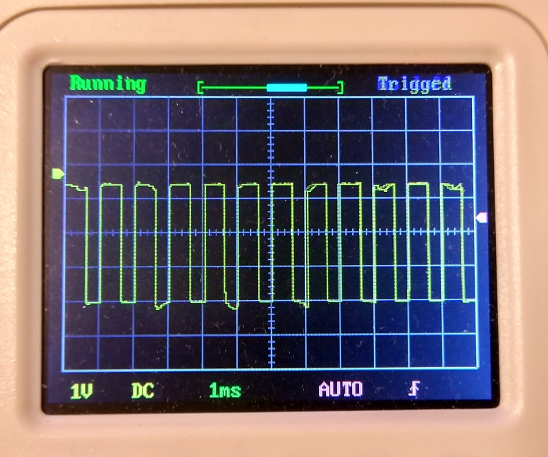
But this thing can be circumvented. Alignment at 1ms occurs for the following reason. An interrupt from USB or from DMA is not tied to anything and can happen somewhere in the middle of a tick. If the interrupt changed the state of the synchronization object (for example, it unlocked the semaphore, or added a message to the queue), then FreeRTOS will not immediately know about it. When the interruption does its job, control is transferred to the thread that worked before the interruption. When the tick ends, the scheduler is called, and depending on the state of the synchronization object, it can switch to the corresponding stream.
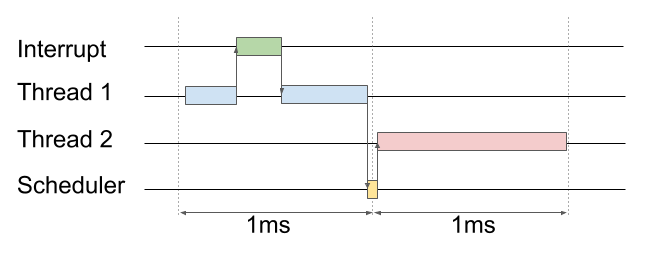
But just for such cases, FreeRTOS has a mechanism for forcing the scheduler. As I said, you cannot interrupt an interrupt. But you can hint at the need to call the scheduler (I emphasize: do not call the scheduler, but hint at the need to call). This is exactly what the portYIELD_FROM_ISR () function does.
We ask the scheduler to switch flows immediately after interruption
void SdFatSPIDriver::dmaTransferCompletedCB()
{
	// Resume SD thread
	BaseType_t xHigherPriorityTaskWoken;
	xSemaphoreGiveFromISR(xSema, &xHigherPriorityTaskWoken);
	portYIELD_FROM_ISR(xHigherPriorityTaskWoken);
}
Now when the interrupt processing (say, from DMA) finishes, the PendSV interrupt will be automatically called, in the handler of which the scheduler is called. That, in turn, forcibly switches the context and transfers control to the thread that was waiting for the semaphore. T.O. the interrupt response time can be significantly reduced, and as a result, this trick allows you to accelerate reading on the test card right up to 600kb / s!
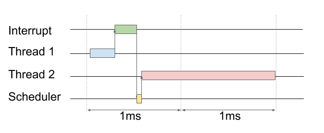
But this is if there is no long wait for the readiness of the card. Unfortunately, if the card thinks for a long time, then reading stretches for 2 ticks (and writing for 4-6) and the speed is significantly lower. Moreover, if the active waiting code is constantly hammering into the card, and the card does not respond for a long time, then a whole tick can pass. In this case, the OS scheduler may decide that this thread has been running for too long and generally switch control to other threads. Because of this, an additional delay may occur.
By the way, I tested all this on an 8GB class 6 card. I also tried several other cards that I had on hand. Another card is also 8GB but class 10 for some reason gave out only 300-350 kb / s for reading, but 120 kb / s for writing. I even ventured to put the largest and fastest card that I had - 32GB. It was possible to achieve maximum speeds with it - 650kb / s for reading and 120kb / s for writing. By the way, the speeds that I quote are average. I had nothing to measure instantaneous speed.
What conclusions can be drawn from this analysis?
- Firstly, SPI is clearly not a native interface for SD cards. Even cool cards are dumb on the most common operations. It makes sense to look towards SDIO (I already picked up a bag with STM32F103RCT6 in the mail - there is SDIO support out of the box)
- Во-вторых, карта карте рознь. Нужно будет искать ту единственную. Хотя при подключении через SDIO это будет не так критично
- В-третьих, при наличии достаточного количества памяти можно будет переключиться на чтение блоками бОльшего размера (скажем 4к). Тогда длинная задержка вначале чтения/записи будет нивелироваться большой скоростью передачи. Пока 20кб памяти моего контроллера (STM32F103C8T6) забиты почти под завязку и даже 512 байт для двойной буферизации я выкроил с трудом
Заключение
In this article, I talked about how I was able to upgrade the USB MSC implementation from STMicroelectronics. Unlike other STM32 series microcontrollers, the F103 series does not have built-in DMA support for USB. But with the help of FreeRTOS, I managed to fasten the read / write of the SD card via DMA. Well, in order to use the USB bus bandwidth as efficiently as possible, I managed to tighten the double buffering.
The result exceeded my expectations. Initially, I aimed at a speed of about 400kb / s, but I managed to squeeze as much as 650kb / s. But for me, it’s important not even the absolute speed indicators, but the fact that this speed is achieved with minimal processor intervention. So the data is transferred using DMA and USB peripherals, and the processor is connected only to charge the next operation.
True, we couldn’t get super speeds with the recording - only 100-120kb / s. The blame for the huge timeouts of the SD card itself. Well, since the card is connected via SPI there is no other way to find out about the readiness of the card (except how to constantly poll it). Because of this, a rather high processor load on write operations is observed. I have the secret hope that connecting the card via SDIO can achieve much higher speeds.
I tried not only to give the code, but also to tell how it is organized and why it is constructed that way. Perhaps this will help to do something similar for other controllers or libraries. I did not allocate this to a separate library, as this code depends on other parts of my project and the FreeRTOS library. Moreover, I built my code on the basis of a very patched implementation of MSC. So if you want to use my version you have to backport it to the original library.
Link to my repository: github.com/grafalex82/GPSLogger
I will be glad to constructive comments and other ideas on how to speed up work with the SD card.