About the quality of requirements in IT projects, frankly (from the position of the development team). Part 2
Part 1 can be found by clicking on the link
As announced in the previous sections, we will try to convert the requirements for software development in such a format that they simplify and speed up the work of the team turning them into a final product.
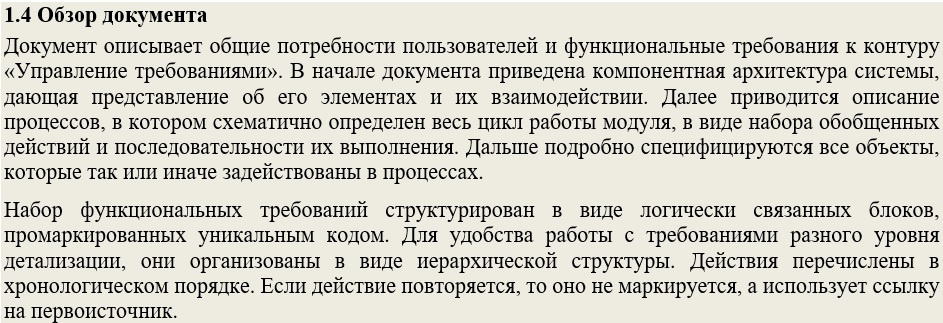
So, where does the acquaintance of the development team with the requirements presented begin? By all means with a presentation by the analyst of his creation, to future performers. It is very important for both parties how successfully the first contact will be established and the barrier to enter the new process is overcome. But often, for a number of reasons, it is impossible or problematic to do this in person. Therefore, it’s good practice to include a section at the beginning of the document, with a brief overview of its structure and presentation of information, as well as an explanation of how to use it correctly and effectively.
An example of a document review:
For a better perception of the context of the developed system, in addition to the sections that we have selected in the document structure - as mandatory, I try to include in the text information about the goals that should be achieved as a result of the development of the target product or its composite module. Developers still need to be aware of what the customer wants to receive at the exit of the project. For the description of this section, formalized Customer Needs are suitable. A similar section is found in most standards, for example, in GOST-34.602-89 [4] it is called "the purpose and objectives of the creation (development) of the system."
It may look like this:
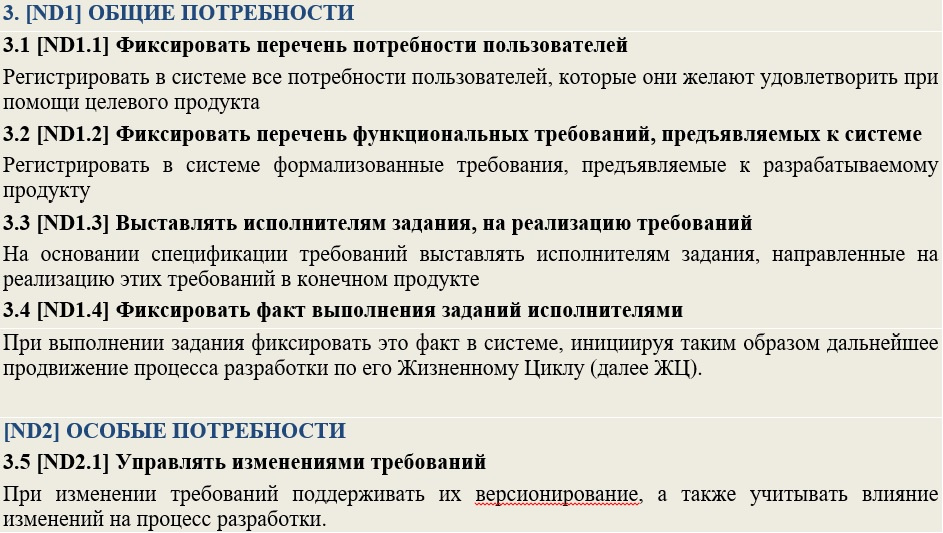
When developing subsequent document artifacts, they should include links to the User Needs recorded in the section discussed above (since each need has its own identifier). Thus, we can make sure that all the goals that the target product of the project must satisfy can be fulfilled during its implementation.
The main problem of large-scale projects is the need to use a large number of components. This fact can significantly impede the common idea in the imagination of team members of the whole picture of the product. To combat this evil, I try to add a section at the beginning of the document that describes the general component architecture of the target product. This section helps to present on one (or several) images all the main nodal elements of the target product, as well as to get acquainted with the description of the methods and modes of interaction between them.
In his work “The Unified Software Development Process” [5], Aivar Jacobson gave the term Architecture the following definition: “this is a representation of the entire project with highlighting important characteristics and shading details”.
In place of the central element of this section, in my opinion, the architecture diagram notation is ideally suited. This type of presentation is similar to the canonical diagram of components, but it looks more visual and accessible for understanding to a wide circle of specialists.
The following is a fragment of the inclusion in the requirements of the section with a description of the system architecture.
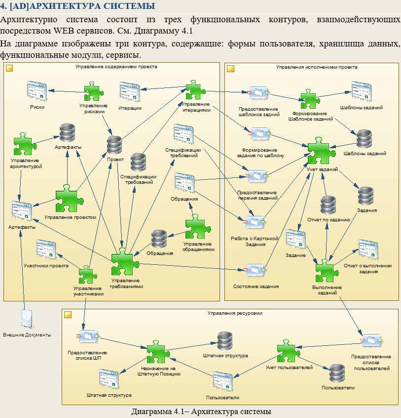
It is advisable to accompany such large, sketchy drawings with text that helps readers understand them.
This representation is especially useful when several teams are involved in a project. They can clearly determine the points (interfaces) of contact between the components of the system, as well as their (teams) interaction. Understanding the general model will allow avoiding the “sagging” of the responsibility of performers in adjacent work areas in the early stages.
If the document does not consider the entire system, but only its part, then this part can be highlighted on the diagram in color. Thus, in different documents the same diagram of component architecture can be repeated, but with different parts (components) highlighted in color.
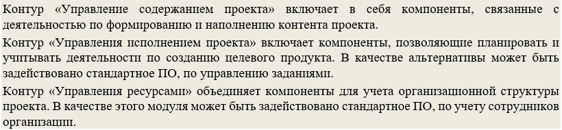
When we introduced the audience to the general needs of the customer and visualized the architecture of the developed product, the reader already has an idea of its main functions and the structure of the system as a whole. Now you can move on to a more detailed acquaintance with the main scenarios of its use. In GOST-34.602-89 [4], such a section is called "requirements for the functions (tasks) performed by the system."
Often, when designing such sections, the requirements use diagrams: UseCase or Description of Business Processes (BPMN), or Execution Algorithms (Activity), or IDEF0 functional models, etc. All these types of diagrams are indispensable at the design stage, defining the scope of a project, etc. But from my experience, they are of little use for programmers. From the point of view of the developers to whom this document is intended, it is much more comfortable to work specifically with scenarios for using the designed system, presented in the form of a structured text description. Summarizing all of the above in this paragraph, I note: do not overload this section with information that no one will use, but will scroll past each time to get to the desired section.
Below is a scenario description option that I often use in practice. The main criteria in developing this approach were as follows:


Such scenarios help developers in the future, in the process of implementing static objects and system components, quickly clarify the dynamics of their interaction. Therefore, further, in the description of Entities, Forms, Procedures, etc. references to the scripts in which they are involved must be used (the benefit of the script, like all other specification objects, we have identifiers).
The same scenarios can serve as the basis for the work of another group of requirements consumers - QA specialists, since they are very close in form to the test scenarios.
Specifications should be grouped and well structured as blocks of information. The block of the lowest level should be an atomic requirement, ready for transfer to the developer in the form of a task. Therefore, each Specification should contain information sufficient for the developer to be able to unambiguously and fully implement the requirement, without contacting the author for clarifications and clarifications. This approach will allow the project manager to go over the specifications, not really straining, to form a set of “blanks” from them to draw up a detailed project schedule. Well, more on that later.
As we agreed in the process of determining the structure and order of following the specifications, the stage of implementation of requirements by developers should begin with the formation of a data warehouse. Therefore, in my version of the specifications, the first section I devote to this topic. At the beginning of the section, for a more complete understanding of the domain model, it is desirable to give a general data structure. This can be done using the class diagram, it is quite popular and known to most IT professionals. The image will allow developers to contemplate the entire structure at once. Next, you need to detail the specifications for each individual Entity that is used in the module.
The following is an example of specifications for the project in question:
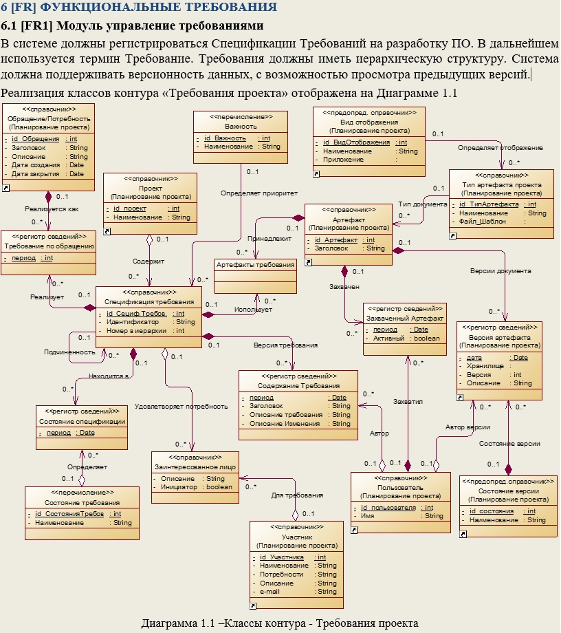
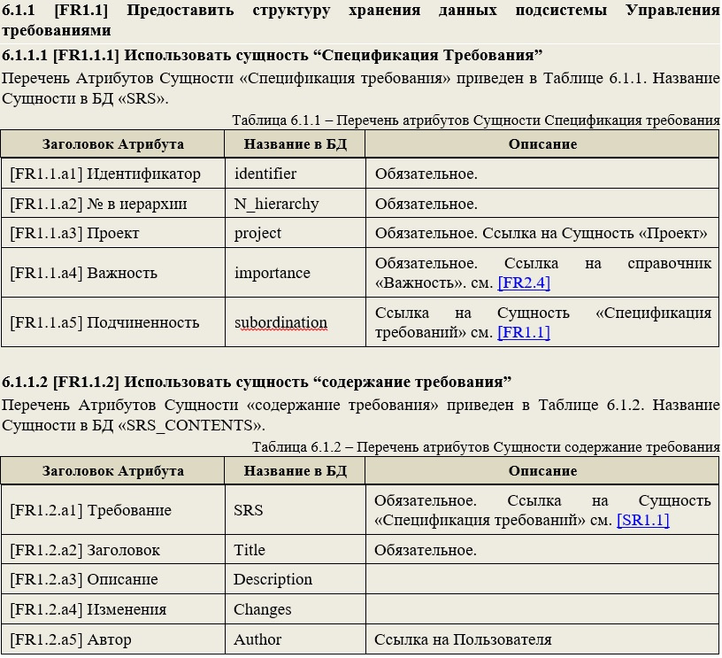
Thus, developers who receive such requirements can only translate them into code for generating database objects (hereinafter referred to as DB). To perform such operations, you can attract specialists with low qualifications and save the project budget.
I recommend breaking the module (system) into subsystems, so that in each of them the reader operates on the number of implemented entities from 3 to 7. This allows: firstly, it is easier to perceive the material, and secondly, several developers can simultaneously develop the module (each implements separate subsystem).
A similar section is in GOST-34.602-89 [4] and it is called "Description of the organization of the information base."
After describing all the Entities that need to be implemented in this module (subsystem), we can begin to develop visual forms. Form requirements are conveniently formatted in the same style. When describing, it is important to rely on the visual components of the user interface provided by the platform on which development is ongoing. When describing forms, it is necessary to indicate which database elements described in the previous section are used to visually represent attributes (since they also have identifiers). And in order for the developers to more fully imagine what they are developing and how it will all move on the screen, in the description of the form, mention should be made of the scenarios in which this form is used, not forgetting to specify the link.
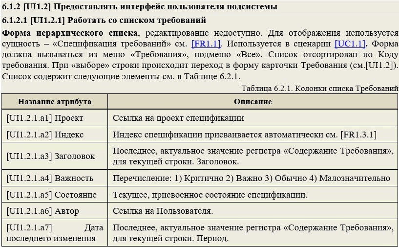
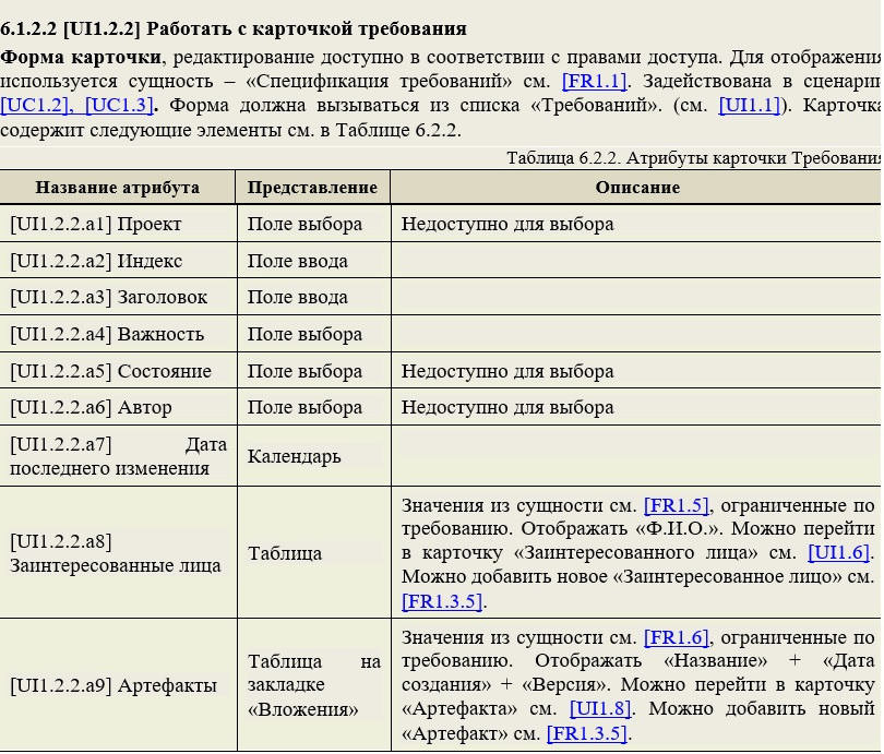
Note that for complex attributes (for example, [UI1.2.2.a9]), the table immediately describes the links to the entity with which it is associated, the restrictions for selecting data, the fields to display on the form, the rules for following links on the form, etc. d. For each attribute, a view corresponding to the visual components of the system is indicated. With such a detailed and unambiguous description, developers can easily implement the requirements for the user interface in a timely manner with predictable quality. Deep detailing also allows you to attract less qualified personnel to work and helps the project manager to efficiently distribute tasks in a team, increasing the profitability of the project as a whole.
After the visual forms are specified, you can begin to program their behavior. Therefore, in the next section, I usually present all the procedures that can be performed automatically when processing form events or initiated by the user when working with GUI elements (buttons, menus, etc.).
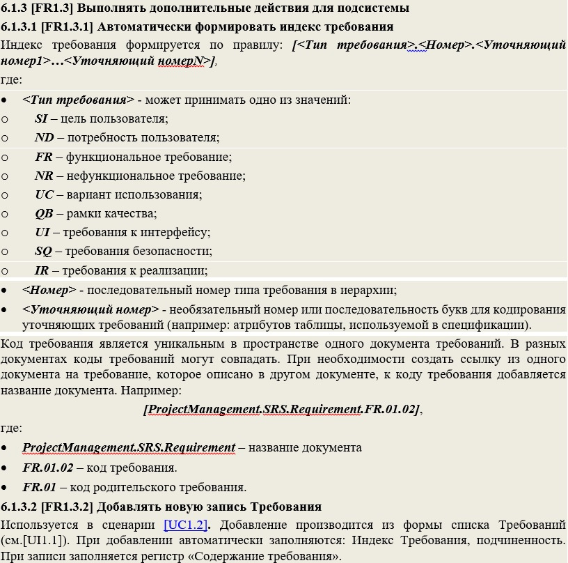
For ease of use, each requirement specification must be assigned a unique identifier. These identifiers can be used as links, both in the requirements themselves and in other project artifacts, including diagrams. A variant of the description of actions, in particular, an identifier generation algorithm, can be viewed in the example requirements below.
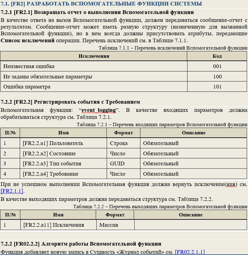
If the module uses complex functions that involve the description of volumetric algorithms, the definition of incoming and outgoing parameters, the development of an additional data storage structure, etc., then I will include a separate section in the document with requirements for auxiliary functions. It may be referenced by specifications describing the actions for the forms discussed above. For example, a helper function is convenient to use when the same basic function is called upon events of different forms. A similar section is in GOST-34.602-89 [4] and it is called "Description of the algorithm."
The following is an example of a similar representation:
Further in the document optionally sections can follow: Reports, Periodic Tasks, Advanced Search, etc. It is advisable to fill in these items with the same level of detail, as shown in the examples above, indicating references to the used entities, procedures, etc.
Another important section, which should be mentioned in the document for such systems, is devoted to access rights. Roles are identified in it, their description is given, and then access rights for these roles to data objects and user interface elements are indicated.
The following is an example of requirements for an access rights management subsystem:
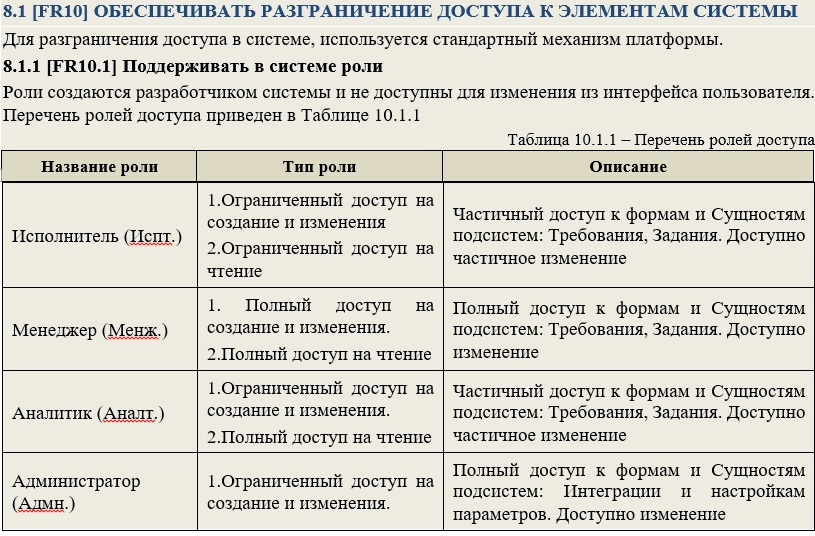
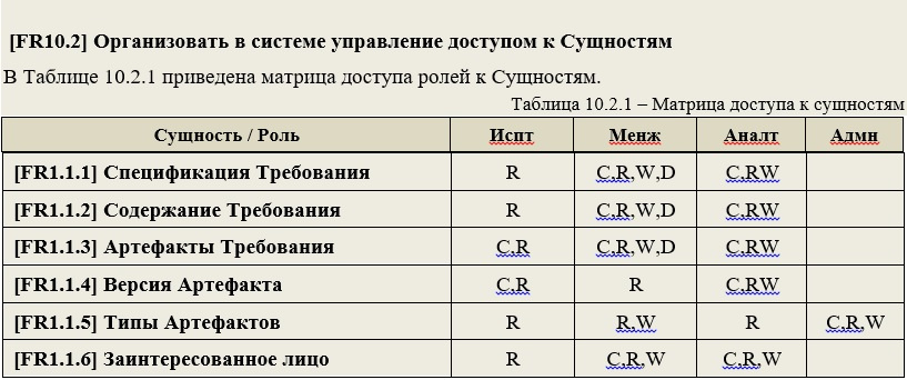
Note that in the above role table example, there is no description of the goals of stakeholders, etc. These details are important for the analyst at the stage of requirements formation, but are practically useless for developers. The next step, for ease of perception, you can create tables in the cells of which the allowed actions for the roles listed as columns will be fixed to the available: procedures, database tables, user interface elements, etc., indicated as rows. And permitted actions can be indicated, for example, in the form of the first letters of English words (C-Create, R-Read, W-Write, etc.) A
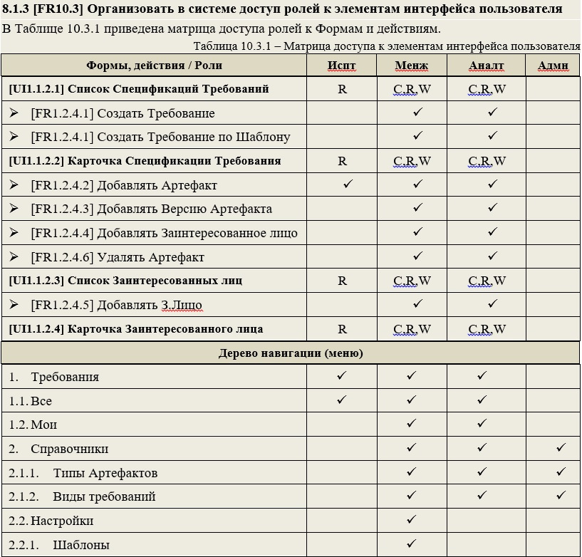
similar subsection is, for example, in GOST-34.602-89 [4] and it is called “ requirements to protect information from unauthorized access. "
In the final part, I will illustrate examples of the effective use of such requirements specifications, PM and QA by link specialists .
.
Design Guidelines for Specification Requirements with Examples
What they don’t talk about, everyone understands in their own way
As announced in the previous sections, we will try to convert the requirements for software development in such a format that they simplify and speed up the work of the team turning them into a final product.
Preparing readers to familiarize themselves with the specifications
So, where does the acquaintance of the development team with the requirements presented begin? By all means with a presentation by the analyst of his creation, to future performers. It is very important for both parties how successfully the first contact will be established and the barrier to enter the new process is overcome. But often, for a number of reasons, it is impossible or problematic to do this in person. Therefore, it’s good practice to include a section at the beginning of the document, with a brief overview of its structure and presentation of information, as well as an explanation of how to use it correctly and effectively.
An example of a document review:
For a better perception of the context of the developed system, in addition to the sections that we have selected in the document structure - as mandatory, I try to include in the text information about the goals that should be achieved as a result of the development of the target product or its composite module. Developers still need to be aware of what the customer wants to receive at the exit of the project. For the description of this section, formalized Customer Needs are suitable. A similar section is found in most standards, for example, in GOST-34.602-89 [4] it is called "the purpose and objectives of the creation (development) of the system."
It may look like this:
When developing subsequent document artifacts, they should include links to the User Needs recorded in the section discussed above (since each need has its own identifier). Thus, we can make sure that all the goals that the target product of the project must satisfy can be fulfilled during its implementation.
Visualize the component structure of the target product
The main problem of large-scale projects is the need to use a large number of components. This fact can significantly impede the common idea in the imagination of team members of the whole picture of the product. To combat this evil, I try to add a section at the beginning of the document that describes the general component architecture of the target product. This section helps to present on one (or several) images all the main nodal elements of the target product, as well as to get acquainted with the description of the methods and modes of interaction between them.
In his work “The Unified Software Development Process” [5], Aivar Jacobson gave the term Architecture the following definition: “this is a representation of the entire project with highlighting important characteristics and shading details”.
In place of the central element of this section, in my opinion, the architecture diagram notation is ideally suited. This type of presentation is similar to the canonical diagram of components, but it looks more visual and accessible for understanding to a wide circle of specialists.
The following is a fragment of the inclusion in the requirements of the section with a description of the system architecture.
It is advisable to accompany such large, sketchy drawings with text that helps readers understand them.
This representation is especially useful when several teams are involved in a project. They can clearly determine the points (interfaces) of contact between the components of the system, as well as their (teams) interaction. Understanding the general model will allow avoiding the “sagging” of the responsibility of performers in adjacent work areas in the early stages.
If the document does not consider the entire system, but only its part, then this part can be highlighted on the diagram in color. Thus, in different documents the same diagram of component architecture can be repeated, but with different parts (components) highlighted in color.
Imagine the target product in dynamics
When we introduced the audience to the general needs of the customer and visualized the architecture of the developed product, the reader already has an idea of its main functions and the structure of the system as a whole. Now you can move on to a more detailed acquaintance with the main scenarios of its use. In GOST-34.602-89 [4], such a section is called "requirements for the functions (tasks) performed by the system."
Often, when designing such sections, the requirements use diagrams: UseCase or Description of Business Processes (BPMN), or Execution Algorithms (Activity), or IDEF0 functional models, etc. All these types of diagrams are indispensable at the design stage, defining the scope of a project, etc. But from my experience, they are of little use for programmers. From the point of view of the developers to whom this document is intended, it is much more comfortable to work specifically with scenarios for using the designed system, presented in the form of a structured text description. Summarizing all of the above in this paragraph, I note: do not overload this section with information that no one will use, but will scroll past each time to get to the desired section.
Below is a scenario description option that I often use in practice. The main criteria in developing this approach were as follows:
- Participants working with the description do not have special training and are not free to read notations;
- Readers of the description should clearly and fully imagine all the actions that will be performed by users using the target product (module, subsystem, etc.);
- It is necessary to structure and present information using the techniques of best practices for describing processes;
Such scenarios help developers in the future, in the process of implementing static objects and system components, quickly clarify the dynamics of their interaction. Therefore, further, in the description of Entities, Forms, Procedures, etc. references to the scripts in which they are involved must be used (the benefit of the script, like all other specification objects, we have identifiers).
The same scenarios can serve as the basis for the work of another group of requirements consumers - QA specialists, since they are very close in form to the test scenarios.
DETERMINE THE COMPOSITION AND FORM OF SPECIFICATIONS OF REQUIREMENTS
Requirements specifications - this is not a solution with answers, but a consistent action planNow that all the familiarization sections have been prepared, you can proceed to the formation of the key part of the document - the specifications of functional requirements, which will serve as a starting point for the formation of tasks for developers.
Specifications should be grouped and well structured as blocks of information. The block of the lowest level should be an atomic requirement, ready for transfer to the developer in the form of a task. Therefore, each Specification should contain information sufficient for the developer to be able to unambiguously and fully implement the requirement, without contacting the author for clarifications and clarifications. This approach will allow the project manager to go over the specifications, not really straining, to form a set of “blanks” from them to draw up a detailed project schedule. Well, more on that later.
Let's start with storage
As we agreed in the process of determining the structure and order of following the specifications, the stage of implementation of requirements by developers should begin with the formation of a data warehouse. Therefore, in my version of the specifications, the first section I devote to this topic. At the beginning of the section, for a more complete understanding of the domain model, it is desirable to give a general data structure. This can be done using the class diagram, it is quite popular and known to most IT professionals. The image will allow developers to contemplate the entire structure at once. Next, you need to detail the specifications for each individual Entity that is used in the module.
The following is an example of specifications for the project in question:
Thus, developers who receive such requirements can only translate them into code for generating database objects (hereinafter referred to as DB). To perform such operations, you can attract specialists with low qualifications and save the project budget.
I recommend breaking the module (system) into subsystems, so that in each of them the reader operates on the number of implemented entities from 3 to 7. This allows: firstly, it is easier to perceive the material, and secondly, several developers can simultaneously develop the module (each implements separate subsystem).
A similar section is in GOST-34.602-89 [4] and it is called "Description of the organization of the information base."
From data storage, let's move on to displaying them on visual forms
After describing all the Entities that need to be implemented in this module (subsystem), we can begin to develop visual forms. Form requirements are conveniently formatted in the same style. When describing, it is important to rely on the visual components of the user interface provided by the platform on which development is ongoing. When describing forms, it is necessary to indicate which database elements described in the previous section are used to visually represent attributes (since they also have identifiers). And in order for the developers to more fully imagine what they are developing and how it will all move on the screen, in the description of the form, mention should be made of the scenarios in which this form is used, not forgetting to specify the link.
Note that for complex attributes (for example, [UI1.2.2.a9]), the table immediately describes the links to the entity with which it is associated, the restrictions for selecting data, the fields to display on the form, the rules for following links on the form, etc. d. For each attribute, a view corresponding to the visual components of the system is indicated. With such a detailed and unambiguous description, developers can easily implement the requirements for the user interface in a timely manner with predictable quality. Deep detailing also allows you to attract less qualified personnel to work and helps the project manager to efficiently distribute tasks in a team, increasing the profitability of the project as a whole.
Give visual forms behavior
After the visual forms are specified, you can begin to program their behavior. Therefore, in the next section, I usually present all the procedures that can be performed automatically when processing form events or initiated by the user when working with GUI elements (buttons, menus, etc.).
For ease of use, each requirement specification must be assigned a unique identifier. These identifiers can be used as links, both in the requirements themselves and in other project artifacts, including diagrams. A variant of the description of actions, in particular, an identifier generation algorithm, can be viewed in the example requirements below.
If the module uses complex functions that involve the description of volumetric algorithms, the definition of incoming and outgoing parameters, the development of an additional data storage structure, etc., then I will include a separate section in the document with requirements for auxiliary functions. It may be referenced by specifications describing the actions for the forms discussed above. For example, a helper function is convenient to use when the same basic function is called upon events of different forms. A similar section is in GOST-34.602-89 [4] and it is called "Description of the algorithm."
The following is an example of a similar representation:
Further in the document optionally sections can follow: Reports, Periodic Tasks, Advanced Search, etc. It is advisable to fill in these items with the same level of detail, as shown in the examples above, indicating references to the used entities, procedures, etc.
Take care of security
Another important section, which should be mentioned in the document for such systems, is devoted to access rights. Roles are identified in it, their description is given, and then access rights for these roles to data objects and user interface elements are indicated.
The following is an example of requirements for an access rights management subsystem:
Note that in the above role table example, there is no description of the goals of stakeholders, etc. These details are important for the analyst at the stage of requirements formation, but are practically useless for developers. The next step, for ease of perception, you can create tables in the cells of which the allowed actions for the roles listed as columns will be fixed to the available: procedures, database tables, user interface elements, etc., indicated as rows. And permitted actions can be indicated, for example, in the form of the first letters of English words (C-Create, R-Read, W-Write, etc.) A
similar subsection is, for example, in GOST-34.602-89 [4] and it is called “ requirements to protect information from unauthorized access. "
In the final part, I will illustrate examples of the effective use of such requirements specifications, PM and QA by link specialists .
.
List of references
[1] K. I. Wigers, Development of software requirements, Russian Edition Publishing and Trading House, 2004, p. 576.
[2] A. Coburn, “Modern Methods for Describing Functional Requirements,” Laurie, 2002, p. 288.
[3] W. D. Leffingwell Dean, Principles for Working with Software Requirements, Williams, 2002, p. 448.
[4] GOST 34.602-89 “Information technology. Set of standards for automated systems. The terms of reference for the creation of an automated system. "
[5] B. G. R. D. Jacobson A., Unified Software Development Process, Peter, 2002, p. 496.