Multicore MRI Method
I will talk about multi-core medical magnetic resonance imaging - one of the many areas of MRI development. I will touch on the features of the method, the necessary technical solutions, the application and the prospects.
For a start, a little excursion into the basics of MRI.
The Basics of MRI
The process of the MRI can be described in the following steps:
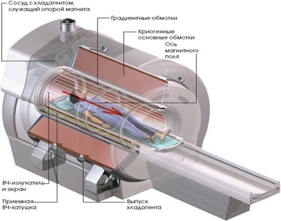
- The object under study is placed in a constant magnetic field of a large, as a rule, superconducting main magnet . The field strength of this magnet is indicated by
 and the axis along which it is directed, denoted Z axis . It is the fielddetermines how much Tesla this MR scanner has. In clinics tomographs with 1.5 T and 3 T are used. MRI tomographs with ultra-high fields - 7 T, 9.4 T, are found only in research institutes.
 - The nuclei of some chemical elements have their own non-zero magnetic moment. The presence of a magnetic moment in a nucleus is caused by the inherent quantum property of particles — spin . Under the influence of the fieldThe magnetic moments of the nuclei are oriented parallel (most) and antiparallel (a smaller part) to the lines of force. Together, these nuclei give the object macroscopic magnetization in the direction along the Z axis.

In addition, the cores precess . So far, the precession does not affect the overall magnetization, since the phases of all nuclei are randomly distributed and the components of their magnetic moments perpendicular to the Z axis cancel each other out. Precession frequency - Larmor frequency , depends only on the magnetic field strength
and the properties of the nucleus - its gyromagnetic ratio.
Where
 - Larmor angular frequency of the precession of the nucleus, [rad / s]; - magnetic field strength, [T];
 Is the gyromagnetic ratio of the core, [rad / (T
 c)].
c)].
The gyromagnetic ratio is defined as where
where  - own magnetic moment of the atom, [A m
 ];
];  - Planck's constant
  Jwith.
Today, medical tomography is based on work with hydrogen atoms, the nucleus of which is an ordinary proton. The nuclei of different chemical elements in the same field will precess at different frequencies. Atoms are interesting for multi-core MRI
 ,
,  ,
,  ,
,  ,
,  ,
, 
Larmor frequencies of some atoms, MHz Atom Gyromagnetic
ratio, MHz / TField strength T1.5 3 7 9.4 
42,58 63.87 127.73 298.04 400.22 11.26 16.89 33.79 78.83 105.86 17.24 25.85 51.71 120.65 162.01 10.71 16.06 32.13 74.96 100.66 40.05 60.08 120.16 280.36 376.49 -5.77 -8.66 -17,32 -40.40 -54.26 From these data you can understand the possible problems of multi-core MRI. The frequencies of other atoms are very different from the frequency of hydrogen; this requires equipping the tomograph with a second set of electronics to work with the RF signal. On the other hand, the frequency of fluorine-19, on the contrary, is close to the frequency of hydrogen, and therefore difficulties arise in differentiating their signals. Ultra-high fields can be used to solve this, in which the frequency step becomes narrower. The gyromagnetic ratio may be negative, like that of oxygen-17. His cores in the same field will precess in the opposite direction compared to others. This must be taken into account at the next stage - excitation of nuclei.
Transmitting RF coil (antenna) creates a magnetic field pulse
 rotating in the XOY plane. Here the phenomenon of resonance occurs , if the frequency of rotation of the field coincides with the Larmor frequency, then the nuclei turn to the XOY plane and synchronize the phases of rotation. If the duration of the RF pulse is such that the magnetic moments of most nuclei are reoriented into the XOY plane, then the pulse is called 90-degree . After a 90-degree pulse, the macroscopic magnetization of an object rotates in the XOY plane with a frequency equal to the Larmor frequency of the nucleus.
In receiving RF coils, this rotating magnetization induces a voltage — a signal (decay) of free induction . Recession, because the relaxation from this state occurs and this special magnetization is lost. Relaxation occurs in two ways. Transverse relaxation , with time constant
 , associated with the loss of synchronization of the phases of rotation of atoms. Longitudinal relaxation , with time constant
 associated with the return of the orientation of the magnetic moments of the nuclei along the field .
In general, to obtain some information about the object is enough. The signal will contain integral, averaged information about these cores of the object. For example, in the frequency spectrum of a signal, one can see chemical shifts — changes in the Larmor frequency due to the interaction of atoms in a chemical compound. This is the basis of NMR spectroscopy, a method used by chemists to analyze the chemical composition of an object.
In this post, I'll talk a little more about RF coils and their features in multi-core MRI.
- В первую очередь необходимо закодировать координаты вокселя, от которого регистрируется сигнал, в свойствах самого сигнала. Для этого используются фазово-частотная кодировка с помощью градиентных катушек. Градиентная катушка создает градиент магнитного поля
 ,
,  ,
,  вдоль соответственно осей X, Y, Z.
Упрощенно процесс кодировки таков:- в момент передачи РЧ импульса подается градиент . Из-за градиента у каждого среза объекта меняется ларморова частота. Получается, что с РЧ импульсом резонирует только один срез – так происходит выбор положения среза.
- между передачей РЧ импульса и считыванием сигнала подается градиент . Из-за него у каждого «столбца» в срезе меняется частота прецессии и за время приложения градиента набегает собственная фаза.
- в момент считывания сигнала подается градиент . Из-за этого частота каждой «строки» в срезе изменяется, что отражается в спектре регистрируемого сигнала.
- в момент передачи РЧ импульса подается градиент
- Контраст на изображении достигается благодаря различию физических свойств у различных типов биологических тканей. Ткани различаются по плотности ядер и временам релаксации и . С помощью последовательностей РЧ импульсов и градиентов можно взвесить амплитуду сигнала с каждого вокселя в зависимости от того или иного физического свойства. Разработка последовательностей, наверное, самая насыщенная область работы в технологии МРТ. Последовательности позволяют кодировать в сигнале информацию о свойствах ткани, которую, казалось бы, в принципе получить невозможно.
- Кроме того в МРТ важна однородность генерируемых магнитных полей, которая неизбежно нарушится из-за помещенного в томограф объекта. Для восстановления однородности используют наборы шиммирующих катушек. Решение проблемы неоднородностей связано с задачами быстрого измерения неоднородностей, создания ограниченным набором катушек компенсирующего поля и одновременно попытка не испортить все из-за наведенных компенсирующими катушками вихревых токов.
RF coil designs
The transmitting (Tx) RF coils are tasked with effectively transmitting a pulse of a given frequency and creating a uniform magnetic field perpendicular to the Z axis. It is interesting that the loss of the RF pulse in the system is enormous. From a few kilowatts of power amplifiers, only tens of watts reach the coils. Therefore, RF coils are made electrically resonating at a given frequency. The design of the RF coil also imposes limitations and anatomy. In MRI studies, often only part of the body is examined — the head, chest, knee, etc. The transmitting coil for the study of the whole body is usually built into the tomograph itself, and for the study of individual parts of the body it is represented by separate modules.

Siemens Head RF Coil
I will give a few examples of coil designs.
Coil in the form of a solenoid.

A simple way to create a uniform field inside the solenoid windings. It may seem that the fields in such a coil rotating can not be done. But it is worth remembering that the vector
, varying according to a sinusoidal law, can be represented as a sum of two oppositely rotating components.Saddle reel

Birdcage reel (birdcage)

On the left is a “birdcage” of the lower frequencies type, on the right - the upper ones.
Advanced option. May be in the form of low frequencies or high frequencies. By adjusting the elements — capacitors and inductances, due to the length of the legs (rarely), the current of the required frequency has a close to ideal sinusoidal distribution in the angle and creates a uniform field. If you give it a quadrature signal, then the field
will be purely rotating.Multi-element coils

The head coil consists of shortened dipole antennas and rectangular loops.
Constructed from several simpler antennas, built around the circumference. Dipole antennas, loop antennas, microstrip antennas, etc. can be used as elements. Here you can see how anatomy affects the design. For example, the emission wavelength of the Larmor frequency of the proton by 7 T is a whole 1 m. A typical dipole antenna should be the field length of the wavelength of the detected radiation. It is impractical to make such a long coil for examining the head, therefore the dipole antenna is shortened by adding inductors to its shoulders.
The function of the receiving coils can be implemented on the transmitting, receiving a receiving-transmitting coil (TxRx). Pure receiving coils (Rx) should also be resonant, but the design requirements are somewhat different. They can be made in the form of a grid of flat loop antennas. So they are located directly on the surface of the body, thereby reducing the loss of the received signal.

Siemens surface receiver coil
Fine tuning the frequency of the coils by changing the capacitance of the capacitors. Also important is the coincidence of the impedances of the coil and the path for efficient energy transfer. The coil impedance using inductances and impedance transformers leads to a standard 50 ohm.
Features of RF coils for multi-core MRI
So, to receive a signal from a hydrogen nucleus and in addition to some other element in MRI, RF coils must have different properties. How to implement it.
- The simplest option. Make two different coils, one for hydrogen, the other for another element. Conduct a full study with a coil for a proton, remove the object and the coil, put another coil to return the object and repeat the study. Given that the MRI examination takes a lot of time and is sensitive to movement, the option is not applicable.
Make coils with double resonance. The second resonant peak can be inserted into the coil by adding an LC circuit in series. Adding additional LC circuits allows you to tune the coil to 3 or more frequencies

Use switches. For example, additional PIN capacitors can be bridged using PIN diodes. So, when DC voltage is applied, the adjustment circuit and the resonant frequency of the coil change accordingly.

Use two (or more) coils simultaneously. Each of them is tuned to its own frequency. Here there is a problem with the mutual inductive coupling between the coils. Often it is solved with the help of a special coil design. Geometry and type of antennas are selected so that the fields they create are orthogonal to each other. Other options - add a passive LC filter to each coil, which removes the signal from the other; using PIN diodes to upset the coil not currently in use.

Coil "birdcage" with four rings. To the usual “cage”, on the one hand and on the other side, one more “cage” is added. The internal segment operates in the same way as a conventional single-frequency coil. The outer segments together form a “bird cage” tailored for another frequency. This design allows the coils to resonate independently of each other.
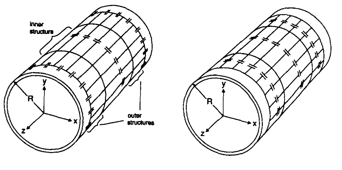
On the left there is a 4-ring "birdcage" with an outer segment of the type of high frequencies, on the right - the lower ones.
Conclusion
In vivo imaging and spectroscopy in MRI studies is a difficult task. The concentration of atoms other than hydrogen in the human body is quite low, because of this, the signal-to-noise ratio when working with these atoms is low. To improve the SNR, MRI with ultrahigh fields is used, but in such fields difficulties arise with field uniformity. With such Tesla, the wavelength of proton radiation is already comparable with the size of body parts.
But the use of other atoms carries valuable information about metabolism. Atomscarry information about the salt balance in the cells. Living healthy cells constantly maintain a low concentration of sodium ions inside themselves at a high outside using sodium-potassium pumps. This process goes with energy costs, therefore metabolic disorders are reflected in changes in the concentration of sodium ions inside the cells. Brain tumors, ischemia, strokes, bipolar disorders are associated with an increase in the concentration of sodium inside the cells and this can be seen with a multi-core MRI.
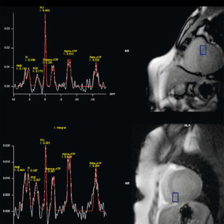
Another example is phosphorus in the form of an atom. . It enters important metabolites - ATP, phosphocreatine, etc. By performing phosphorus spectroscopy in muscles, one can assess the presence of these substances and the level of metabolism in the muscles.
Spectroscopy is already used in NMR spectroscopy for the analysis of organic chemical compounds, but in vivo its concentration in humans is small, but the method is still applicable.
Atom has a low concentration in the natural state, but by saturating the air with which the person under study breathes, it is possible to build a map of its metabolic rate, which helps in the diagnosis of tumors.
But nevertheless, there is still a long way to go before the widespread use in multi-core MRI clinics and it will take 20-30 years.
Sources
- Физика визуализации изображений в медицине: В 2-х томах. Т. 2: Пер. с англ./Под ред. С. Уэбба. — М.: Мир, 1991.
- Медицинские приборы, аппараты, системы и комплексы: Учебник/ Текст Н.А. Кореневский, Е.П. Попечителев, С.П. Серегин; Курск. гос. техн. ун-т. — Курск: ОАО «ИПП „Курск“, 2009.
- Основы МРТ. Джозеф П. Хорнак. www.cis.rit.edu/htbooks/mri
- Разбираем магнитно-резонансный томограф. habr.com/ru/post/405355
- www.healthcare.siemens.com/magnetic-resonance-imaging
- Edelstein, W. A. (2007). Radiofrequency Systems and Coils for MRI and MRS. In eMagRes (eds R. K. Harris and R. L. Wasylishen). doi:10.1002/9780470034590.emrstm0444
- Giovannetti G., Birdcage coils: Equivalent capacitance and equivalent inductance. Concepts Magn. Reson., 44: 32-38. doi:10.1002/cmr.b.21260
- E. Hayes, W. A. Edelstein, J. G. Schenck, O. M. Mueller, and M. Eash, An Efficient, Highly Homogeneous Radiofrequency Coil for Whole-Body NMR Imaging at 1.5 T. J. Magn. Reson. 63, 622 (1985).
- Joel C. Watkins and Eiichi Fukushima, High-pass bird-cage coil for nuclear-magnetic resonance. Review of Scientific Instruments 59, 926 (1988); doi.org/10.1063/1.1139751
- Clément JD, Gruetter R, Ipek Ö. A human cerebral and cerebellar 8-channel transceive RF dipole coil array at 7T. Magn Reson Med. 2019;81:1447–1458. doi.org/10.1002/mrm.27476
- M.D. Schnall, V Harihara Subramanian, J.S Leigh, B Chance, A new double-tuned probed for concurrent 1H and 31P NMR, Journal of Magnetic Resonance (1969), Volume 65, Issue 1, 1985, Pages 122-129, ISSN 0022-2364, doi.org/10.1016/0022-2364(85)90380-4.
- Friedrich Wetterling, Miroslav Högler, Ute Molkenthin, Sven Junge, Lindsay Gallagher, I. Mhairi Macrae, Andrew J. Fagan, The design of a double-tuned two-port surface resonator and its application to in vivo Hydrogen- and Sodium-MRI, Journal of Magnetic Resonance, Volume 217, 2012, Pages 10-18, ISSN 1090-7807, doi.org/10.1016/j.jmr.2012.02.002.
- Chang-Hoon Choi, James M.S. Hutchison, David J. Lurie, Design and construction of an actively frequency-switchable RF coil for field-dependent Magnetisation Transfer Contrast MRI with fast field-cycling, Journal of Magnetic Resonance, Volume 207, Issue 1, 2010, Pages 134-139, ISSN 1090-7807, doi.org/10.1016/j.jmr.2010.08.018.
- Murphy-Boesch J., Srinivasa R., Carvajal L., Brown T.R., Two Configurations of the Four-Ring Birdcage Coil for 1H Imaging and 1H-decoupled 31P Spectroscopy of Human Head. Journal of Magnetic Resonance, Series B 103, 103-114, 1994.
- Murphy-Boesch J. Double-Tuned Birdcage Coils: Construction and Tuning. In eMagRes (eds R. K. Harris and R. L. Wasylishen). doi:10.1002/9780470034590.emrstm1121
- Sandro Romanzetti, Christian C. Mirkes, Daniel P. Fiege, Avdo Celik, Jörg Felder, N. Jon Shah, Mapping tissue sodium concentration in the human brain: A comparison of MR sequences at 9.4Tesla, NeuroImage, Volume 96, 2014, Pages 44-53, ISSN 1053-8119, doi.org/10.1016/j.neuroimage.2014.03.079.