 May 7, 2017 at 15:18
Count to three: three
Trinity Counter
So, we continue the conversation. In this article I will tell you how to make a ternary counter. I remind you that I want to make a simple, but programmable piece of hardware that works on ternary logic. The answer to the question “why?” look here .
This is the third article, and will be continued as soon as it is ready. Table of contents:
- Counting up to three: times (ternary multiplexer and adders)
- Count to three: two (memory)
- We count to three: three (counters)
- We count to three: four (single-digit computer and three-command command system)
As usual, in my articles there are more pictures than text. This is how the main piece of iron looks, which will be discussed today:

Summary of previous episodes
Trinity Multiplexer
I recall that the only used element of the whole design will be the ternary multiplexer, which, in fact, is a three-position switch. Logically, this is a thing about five pins: one of them (sel) receives a ternary selector signal, and depending on it, one of three input signals inN, inO or inP is sent to the output of the multiplexer (out):

This is how the board looks carries two (de) multiplexers. I, following the original name , will call it the word "trimux".
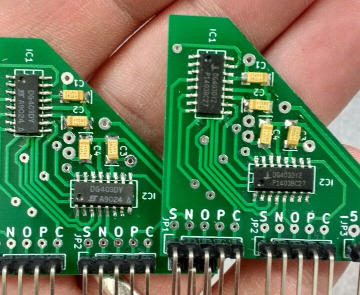
If the multiplexer is connected simply as a repeater, applying -5V, 0V, + 5V to the legs N, O, P, respectively, then when applying a triangle to the input S, the output C will be a step signal:

Today I will use only two things: a half-adder and a memory cell .
Half adder
In the first article, we examined in detail the operation of a half-adder. On the breadboard model it looks something like this: The

top breadboard is the half-adder itself, and the bottom breadboard is the I / O board. Since I will need a fair amount of half-admitters, and it’s too time-consuming to assemble a separate breadboard each time, I decided to make a separate half-adder board. This is how the divorced board looks:
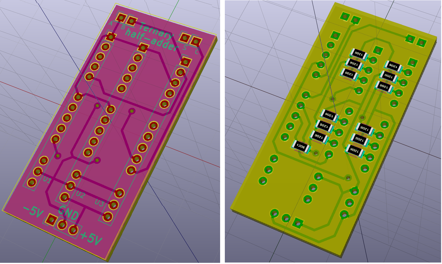
This is how it is already manufactured:

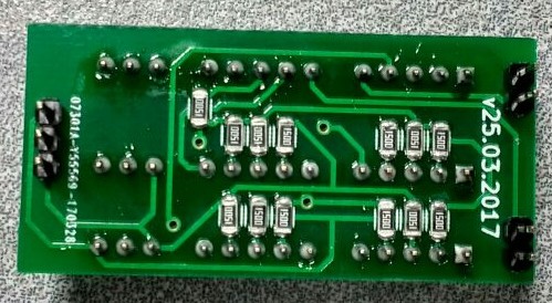
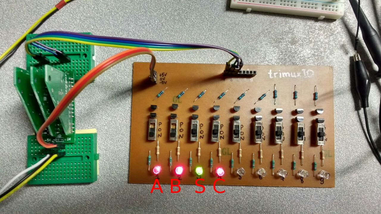
Three trimux plugs into this board. This is not a departure from my intention to use multiplexers exclusively as a building block, since on the auxiliary board I have in fact only wires that save me time. Even the resistors I have are only as a paranoid current limit, they can be safely thrown out. Computing is still doing trimuxes. Here I am testing the operation of a half-adder, the I / O board also outgrew the breadboard:
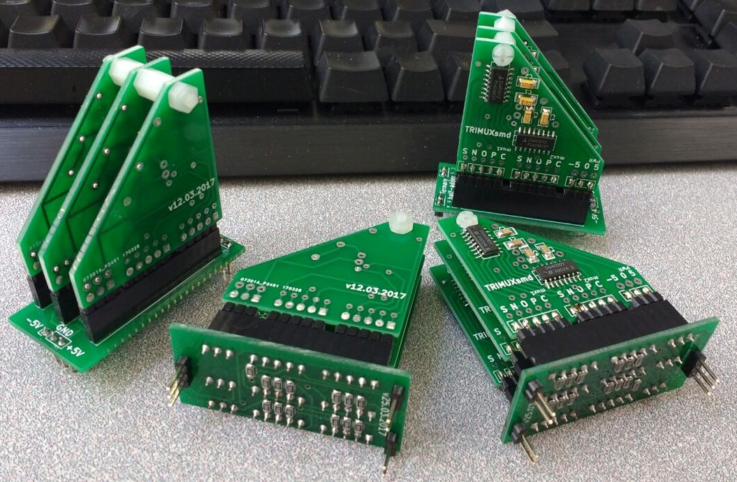
Well, this is how the half-adder modules ready for operation look like:
Ternary memory
In the second article, we figured out that on one trimux (on two ternary multiplexers) you can make a memory cell (ternary latch) with memorization by level. Well, if you assemble two ternary latches into the master and slave, you can get a memory cell with dynamic control, which is triggered by the edge of the clock signal (ternary master-slave flip-flap-flop).
Moreover, in the comments to the previous article, the respected mayorovp proposed an option that uses only four multiplexers. I promised to try and tried!
Here is his suggestion, which I drew for my needs:
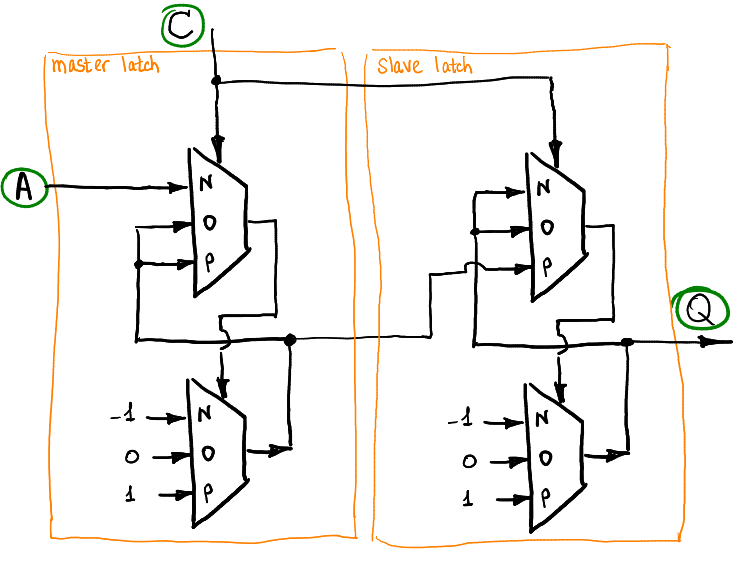
This cell remembers output Q, the value applied to input A, when at the input C the clock signal makes two successive steps NO, OP.
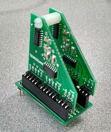
Just like with a half-adder, I decided to make a separate memory unit, here is a divorced board:
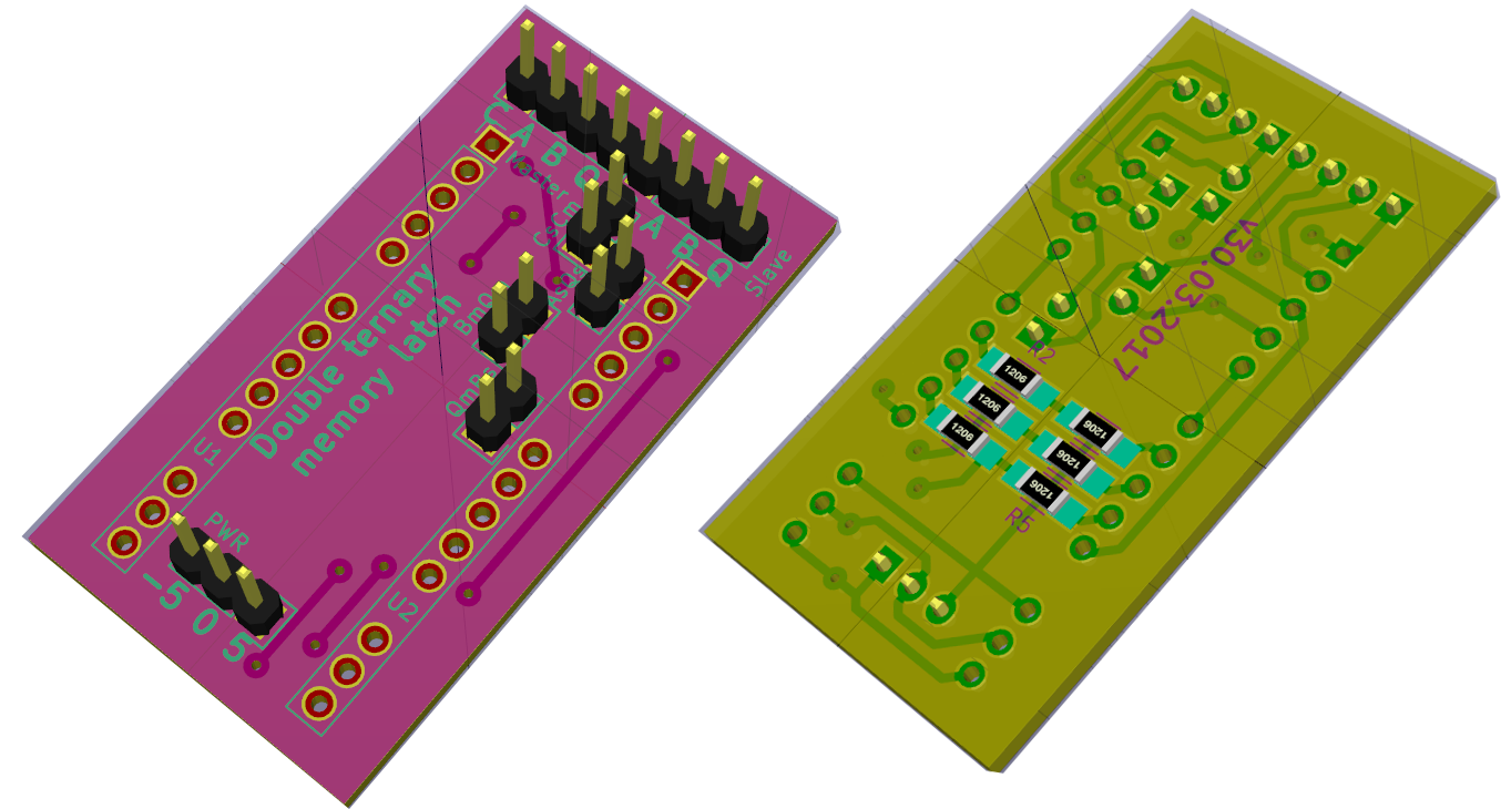
It carries two separate ternary latches that operate on a level. If you install four jumpers, we get the above-described dynamic memory cell.
This is what the scarf looks like:
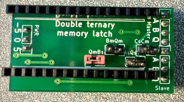
Well, this is the finished module:
The simplest ternary counter
Total, we can slightly abstract from directly multiplexers and use higher-level blocks. Let's take three memory cells and three half adders. This is enough to create the simplest ternary counter.
In total, we have six ready-made blocks that can be connected like this:
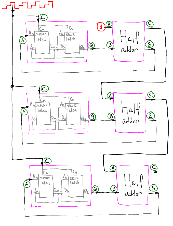
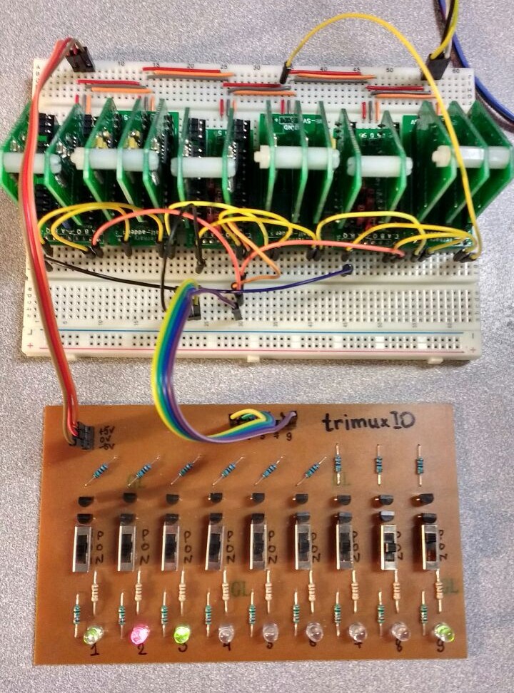
A ternary sawtooth signal is sent to the clock input. In fact, a memory cell plus a half-adder gives a simple frequency divider. If instead of the red unit, submit minus one, then the counter will subtract. This is how our counter looks on the breadboard, the three left LEDs on the I / O board show the status of three memory cells, the rightmost switch is used to manually clock the counter:
And here is a video where I simply click through all 27 possible states of our counter:
Among the shortcomings of this counter, it can be noted that when it is turned on, its state is not very defined (in practice, after a long shutdown, it will be in the zero state). Yes, and resetting this counter is nontrivial. At least I did not find an easy way.
Let's complicate
So, it works well, thank you very much mayorovp for the proposed memory option. If we return to the previous article, then to create a dynamic memory cell, I used two more multiplexers than suggested by mayorovp . Let's try along with them:
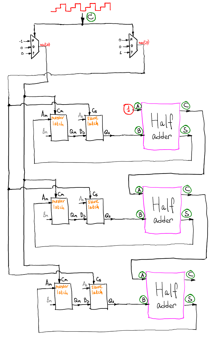
This counter works exactly the same as the previous one, but has two more multiplexers. What for? Because I want it so much! Please note that the inputs Bm and As (I painted them gray) are not used in this circuit. The timing signal on the master latch is never positive, and on the follower, it is never negative.
Now let's add two more multiplexers to the circuit:

If the input signal R is equal to minus one, then the counter is absolutely equivalent to the previous one. But what happens if it is zero or positive? The latches will remember what is fed to the inputs of Bm and As!
We got a ternary counter, which can be read in both directions, and the value of which can be rewritten if necessary, by applying the desired number to the latches and resetting the signal R. Here is a video with a detailed description of the operation:
In total, with the help of thirty-four multiplexers (seventeen trimuxes), a fully working ternary counter is assembled. Its capacity can be reduced to the necessary by adding one memory block and one half-adder per trit.
Look how Alexander Shabarshin suggests making a minute counter in ternary hours (well, or seconds, hours, the scheme is the same):
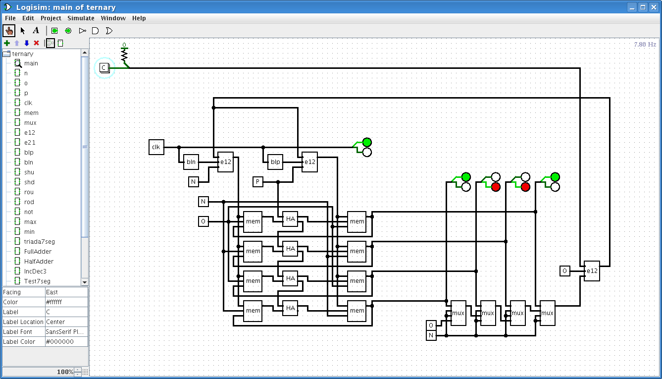
At one hour, sixty minutes, so we have to use four trit. Four trit can hold 81 different values, but in a balanced ternary system they represent values from -40 to 40. How to represent, for example, 45 minutes? Alexander very witty offers to say that now is not 45 minutes, but at fifteen hours! Five multiplexers at the bottom right of the circuit just reset the minute counter after an hour.
That's all for today, next time we’ll try to calculate something.
Bonus: food
Brief description of manufacturing BP
When I wrote the first two articles, in order to get bipolar power, I used the simplest resistor divider, which was heated mercilessly. Since I needed to make a triangle generator, which also requires bipolar power, but already ± 12 V, then I decided that two LATRs in one circuit - this is already overkill and collective farm PSU. I ordered ready-made power modules in China, put it together:
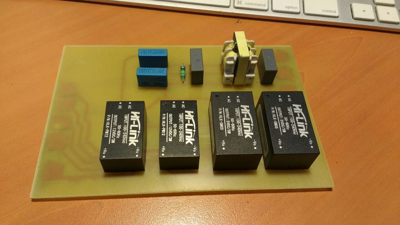
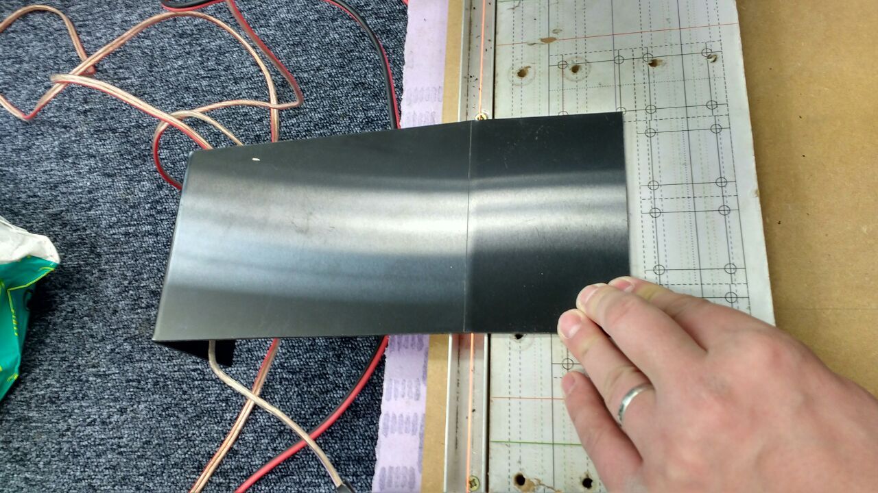
I don’t know why, but for some reason I plugged in a power filter before the power supply. Since here we are talking about 230 volts, the casing is obligatory, I took a 3mm thick PVC sheet, bent it on a nichrome wire:
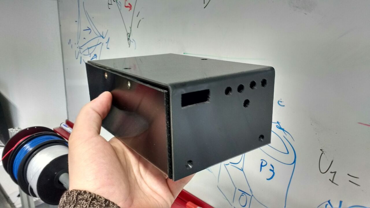
I got something like this case:
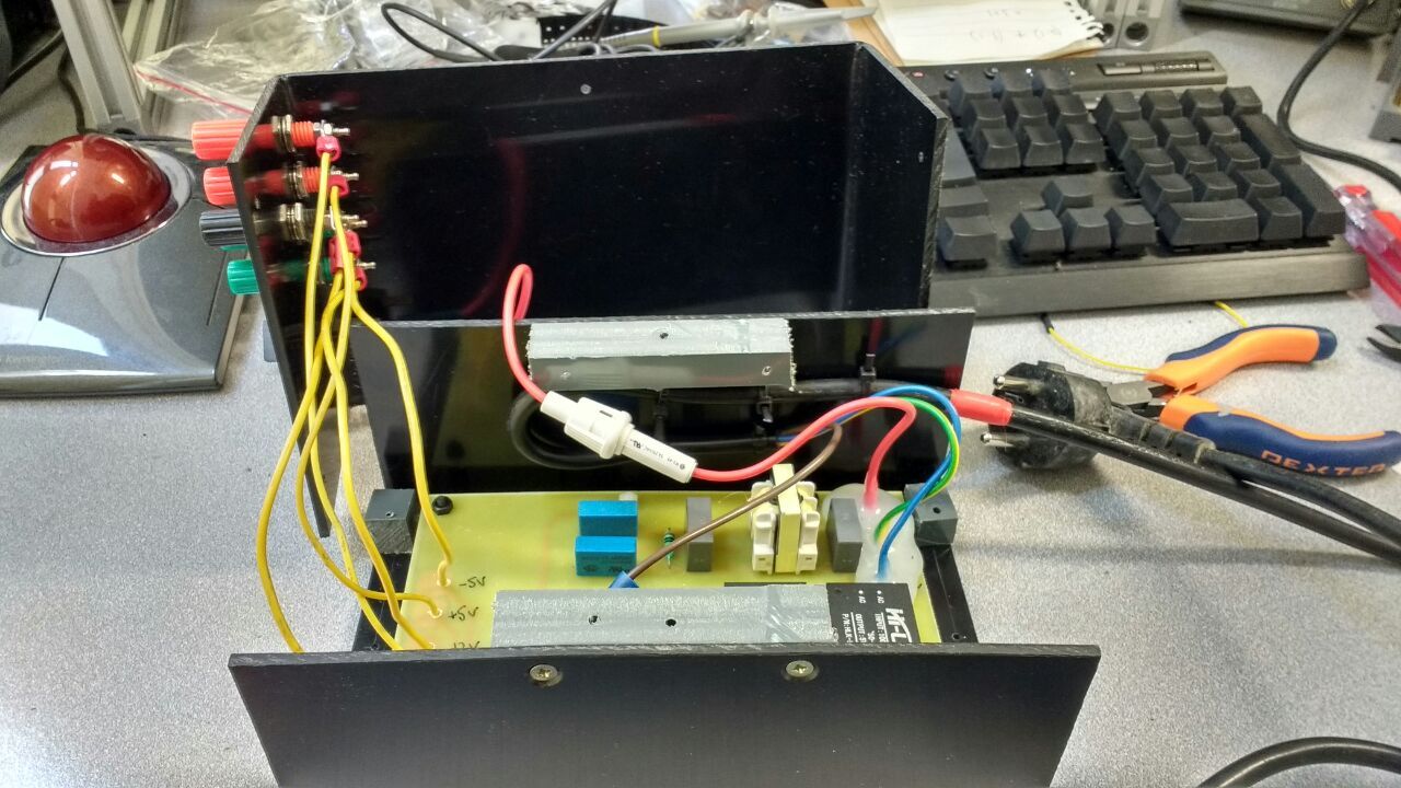
This is how an open PSU looks like:
Ready to use it like this: I
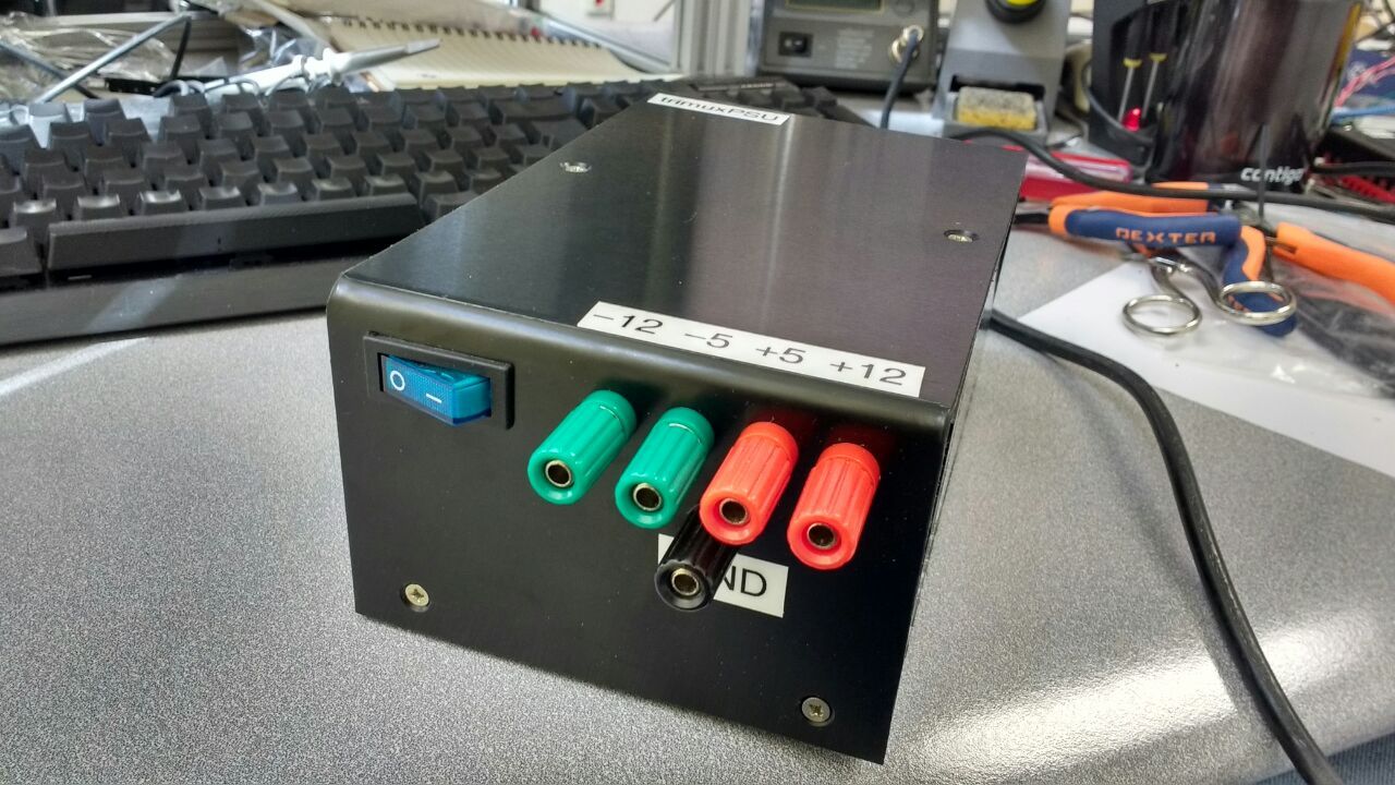
didn’t count the total cost, but roughly estimated would be thirty bucks.
I don’t know why, but for some reason I plugged in a power filter before the power supply. Since here we are talking about 230 volts, the casing is obligatory, I took a 3mm thick PVC sheet, bent it on a nichrome wire:
I got something like this case:
This is how an open PSU looks like:
Ready to use it like this: I
didn’t count the total cost, but roughly estimated would be thirty bucks.









