Implementation of the MIL-STD-1553 protocol on STM32
Once, it became necessary to use a multiplex information exchange channel (MKIO) in our device, it is also GOST R 52070-2003, it is also MIL-STD-1553В. The initial search result was somewhat surprising: typical solutions issued by a search engine, as a rule, were based on the use of FPGAs. Since it was necessary to solve the problem quickly, there was an idea to make a protocol converter from MIL-STD-1553 to MODBUS RTU. At the same time, try to use fairly inexpensive technical solutions and a microcontroller from the STM32 family.
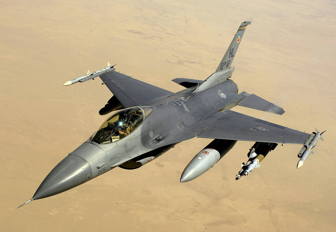
On the photo from Wikipedia: F16, on which the MIL-STD-1553B bus was first used. Our devices do not fly :), so there are no restrictions on the use of the element base. It’s just that the Customer’s instrument network is based on this bus. The first part of the article describes the reception and transmission on the ICIP bus, the second part will be about the converter to MODBUS.
The first stage of any development: search for information and reading documentation. After this stage, the following happened in my head:
- the protocol is quite simple :)
- the maximum frame is 32 bytes :)
- it has pretty tight timing :(
- pretty expensive chips and modules :(
After some thought, I stopped at the use of the HI-15530 encoder - decoder, made by HOLT, but there are a lot of analogs in this microcircuit. True, not everyone can be available in Russia for a reasonable amount of money and time. :)
Here is an example diagram of the inclusion of this chip. The truth is taken from an analog datasheet. :)
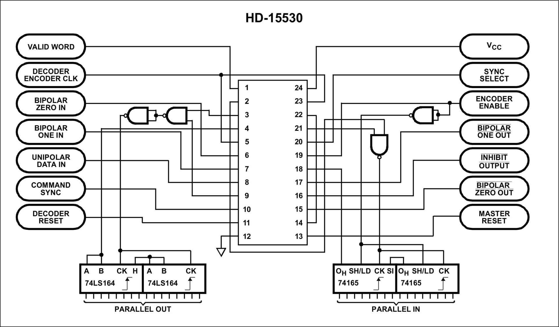
Then everything is simple :) We connect 16-bit data buses to the microprocessor ports: PARALLEL IN and PARALLEL OUT and control signals:
- VALID WORD (The correct word
is accepted) - ENCODER ENABLE (Start transmitting the word)
- COMMAND SYNC (Select command / data)
Instead of register 74LS164, I had to use an analogue of EKF1533IR8. In addition, SN74ALS1035 repeaters (EKF1533LP17) with an open collector are used to match 3.3V signals (STM32) to 5V (HI-15530).
After some correspondence with manufacturers and suppliers, the ELKUS EL-15N transceiver was selected.

Another control signal ST (Transmitter Turn On) was added. This is the result of
such a board.

Debugging software has begun. To simulate the exchange of data with the channel, a USB module was purchased from the company "Module", which can be either a terminal device (OS) or a bus controller (KSh).

The module is supplied with the PURUMK control program. The program of reception and transmission turned out to be quite simple.
Reception of a 16-bit word occurs upon interruption from a VALID WORD signal:
Processing the flag of the received word:
And actually the data transfer to the channel. Each word is transmitted to the channel by interruption of the timer.
And here is the result.
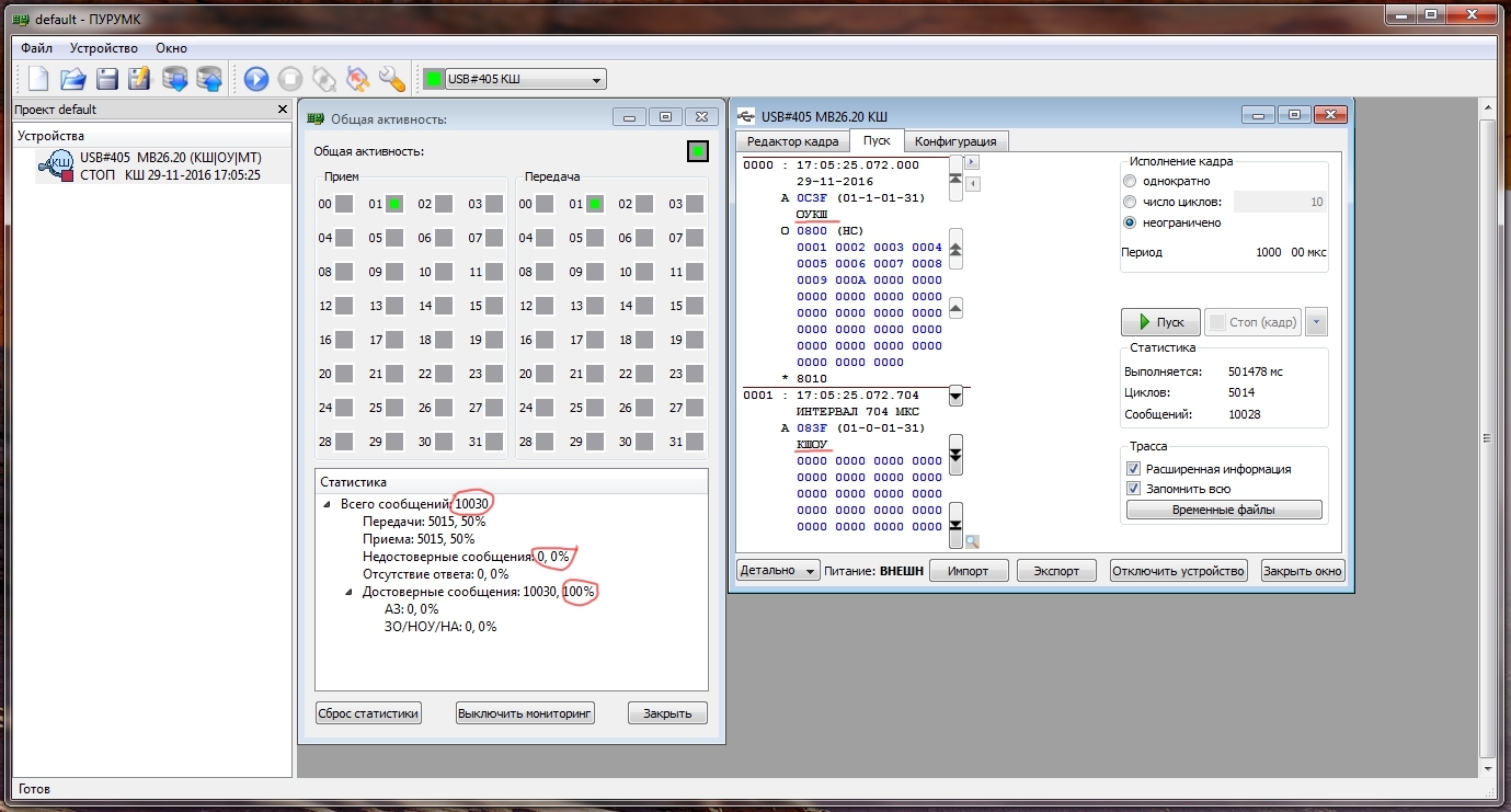
The abbreviations OUKSH and KSHOU mean, respectively: the terminal device to the bus controller, the bus controller to the terminal device. That is, in the first case, a request for data transmission from the OS, and in the second case, data transfer to a terminal device. In both cases, 31 words are transmitted. More than 10,000 words received and transmitted, and not a single error. :)
On the photo from Wikipedia: F16, on which the MIL-STD-1553B bus was first used. Our devices do not fly :), so there are no restrictions on the use of the element base. It’s just that the Customer’s instrument network is based on this bus. The first part of the article describes the reception and transmission on the ICIP bus, the second part will be about the converter to MODBUS.
The first stage of any development: search for information and reading documentation. After this stage, the following happened in my head:
- the protocol is quite simple :)
- the maximum frame is 32 bytes :)
- it has pretty tight timing :(
- pretty expensive chips and modules :(
After some thought, I stopped at the use of the HI-15530 encoder - decoder, made by HOLT, but there are a lot of analogs in this microcircuit. True, not everyone can be available in Russia for a reasonable amount of money and time. :)
Here is an example diagram of the inclusion of this chip. The truth is taken from an analog datasheet. :)
Then everything is simple :) We connect 16-bit data buses to the microprocessor ports: PARALLEL IN and PARALLEL OUT and control signals:
- VALID WORD (The correct word
is accepted) - ENCODER ENABLE (Start transmitting the word)
- COMMAND SYNC (Select command / data)
Instead of register 74LS164, I had to use an analogue of EKF1533IR8. In addition, SN74ALS1035 repeaters (EKF1533LP17) with an open collector are used to match 3.3V signals (STM32) to 5V (HI-15530).
After some correspondence with manufacturers and suppliers, the ELKUS EL-15N transceiver was selected.
Another control signal ST (Transmitter Turn On) was added. This is the result of
such a board.
Debugging software has begun. To simulate the exchange of data with the channel, a USB module was purchased from the company "Module", which can be either a terminal device (OS) or a bus controller (KSh).
The module is supplied with the PURUMK control program. The program of reception and transmission turned out to be quite simple.
Reception of a 16-bit word occurs upon interruption from a VALID WORD signal:
void EXTI9_5_IRQHandler (void) //Valid Word
{
    Ctrl_LED3_ON
    EXTI->PR|=0x0040; //Очищаем флаг
    STD1553_RX_buffer[recieve_count] = GPIOE->IDR;
    recieve_count++;
    frame_from_channel = 1; //флаг принятого слова
    Ctrl_LED3_OFF
}
Processing the flag of the received word:
     if (frame_from_channel)
     {
       frame_from_channel = 0;
       switch (Channel_state)
       {
       case 0: //обработка командного слова
         Device_address_recieved = STD1553_RX_buffer[0];
         Device_address_recieved = Device_address_recieved >> 11;
         if (Device_address_recieved == Device_address) //запрос по адресу
         {
           Command_recieved = STD1553_RX_buffer[0];           //сохранение команды в буфере
           Command_recieved = Command_recieved  & 0x001F; //выделение команды/количества слов
           Transmitt_direction = STD1553_RX_buffer[0];
           Transmitt_direction = Transmitt_direction & 0x0400;
           if (Transmitt_direction == 0x0400) //запрос информации в канал
           {
             TRANSMITTER_ENABLE_HIGH;
             //запуск таймера передачи данных
             TIM5->CR1 |= TIM_CR1_CEN;            //Bit 0 CEN: Counter enable
             TIM5->CNT = Transmitt_word_period;   //
             Answer_word_flag = 1;
           }
           else                                 //прием данных из канала
           {
             Channel_state = 1;
           }
         }
         else
         {
           recieve_count = 0;
         }
         break;
       case 1: //прием данных
          if (recieve_count == Command_recieved + 1)
          {
            //передача ответного слова
            TRANSMITTER_ENABLE_HIGH;
            Answer_word_flag = 1;
            Command_recieved = 0;
            //запуск передачи
            TIM5->CR1 |= TIM_CR1_CEN;     //Bit 0 CEN: Counter enable
            TIM5->CNT = Transmitt_word_period;                //
          }
         break;
       } //end of switch
     } //end of if
And actually the data transfer to the channel. Each word is transmitted to the channel by interruption of the timer.
//передача данных по МКИО
void TIM5_IRQHandler (void)  //
{
  EXTI->IMR       &= ~EXTI_IMR_MR6;            //DISABLE Interrupt Mask on line 1
  if (Answer_word_flag)
  {
     SYNC_SELECT_COMMAND;
     Answer_word_flag = 0;
  }
  else
  {
    SYNC_SELECT_DATA;
  }
  GPIOD->ODR = STD1553_TX_buffer[transmitt_count];
  delay(5);
  ENCODER_ENABLE_HIGH;    //запись данных в регистр
  delay(112);
  transmitt_count ++;
  ENCODER_ENABLE_LOW;    //начало передачи данных в канал
  if (transmitt_count > Command_recieved)
  {
    delay(700);
    TIM5->CR1 &= ~TIM_CR1_CEN;              //Bit 0 CEN: Counter enable
    transmitt_count = 0;
    EXTI->IMR       |= EXTI_IMR_MR6;        //ENABLE Interrupt Mask on line 1
    Channel_state = 0;
    recieve_count = 0;
    TRANSMITTER_ENABLE_LOW;
  }
  TIM5->SR = 0;
  TIM5->CNT = 0;
}
And here is the result.
The abbreviations OUKSH and KSHOU mean, respectively: the terminal device to the bus controller, the bus controller to the terminal device. That is, in the first case, a request for data transmission from the OS, and in the second case, data transfer to a terminal device. In both cases, 31 words are transmitted. More than 10,000 words received and transmitted, and not a single error. :)