November 25, 2016 at 08:47
Connecting a character LCD to a board from WD MyBook Live on AppliedMicro APM82181
Good afternoon! The aim of this work was to expand the capabilities of the existing board from NAS WesternDigital MyBook Live.
According to its characteristics, this board is not very bad:
Contents of the article:
1. Connecting the console
2. Download without disk
3. Compilation in LEDE
4. Port management (via LuCI and the console)
5. Connecting to the I2C bus
6. Connecting the PCF8574 port expander
The rest in the next part ...
Additions and comments are welcome. Go!
To work with the board, you need to connect the console locally (although most operations after booting can also be done through SSH). This is done simply, there is enough information on the Internet, for example, here is the WD MyBook Live UART Port .
Connection is made to the RS232 port of the computer through the RS232-UART adapter, because logic levels on the board within 3.3V. The default baud rate is 115200.
The message “Apollo-3G - APM82181 Board, 2 * SATA, 1 * USB” is a bit incorrect, since there is no USB, but only one SATA. This is due to the fact that the bootloader is common to MyBook Live and the DUO model with two disks.
If you do not click anything in the console, an attempt will be made to boot from the hard drive. In our case, it is not there, so the download is stopped by pressing any button.
The u-boot bootloader has many features for working with equipment.
A list of commands can be seen by typing help. Learn more about the bootloader here . In the boot console, you can see that u-boot offers the option of mounting the nfs file system “Type run flash_nfs to mount root filesystem over NFS”. In this case, we will use another option - loading a RAM image from a TFTP server.
A server rises on the computer, for example TFTPD32 ( Official site ), then we configure the board. Set the local IP address and the address of the TFTP server (your computer). They must be from the same subnet:
View the names of the files that will be requested from the TFTP server:
Note that the variable fdt_file contains the name of the device tree file, and bootfile the name of the RAM disk image file with the operating system.
Names can be changed to more convenient ones, similar to addresses with the setenv command. After tuning, it is advisable to save the new values of the variables in the ROM:
Thus, after rebooting or turning off the power, the settings will be saved. After that, we place the two necessary files (if you do not have them, then see the next section for their creation) on the TFTP server and type the command run net_nfs.
As you can see, two files are loaded as a result. They are located in the specified places in the RAM, the kernel is unpacked and loaded. As a result, we have a working system, in this case LEDE:
We will use LEDE as the source of the operating system for our board . This is a fork of OpenWRT and it supports the MyBook Live board. Download here: apm82181-lede . Download packages as written in the instructions:
Launch the configurator:
We select “AppliedMicro APM821xx” as a system (“Target System”), “Devices which boot from SATA (NAS)” as a subsystem (“Subtarget”), and “Western Digital My Book Live” as a profile (“Target System”) . In the final image (“Target Images”), ramdisk must be marked.
We choose packages at our discretion. After saving the settings in the configurator and exiting it, you can start compilation with the make command.
After the end of the process, if it went without errors, the necessary files can be picked up and put on the TFTP server:
Thus, we went through the stages of booting a system without a disk.
I could not find the circuit of this board and generally the circuit of any device based on the APM82181 processor on the Internet. Therefore, we will partially reverse engineer (reverse engineer), that is, guess about the connections on the board and verify this. LEDE developers apparently partially did this, because the connected ports can be seen in the device tree or see information from the kernel:
As you can see, one port is used to enter a button press, the rest to an output for control. It is clear that by editing the device tree file (file with the .dts extension), any port in the operating system can be freed from functions, but this may affect the functionality of the functional blocks of the board. Except for the LED. Ports connected to this indicator can be used for their own purposes. The ports indicated by the question mark are connected to it. And LED control is available, for example, from the console.
By default, after loading, the LEDE indicator lights up in green. So you can turn it off:
And turn on the blue:
If LEDE was built with the LuCI web shell, then the LEDs can be controlled from a browser.
In the System menu, go to LED Configuration, and configure what events each particular LED color triggers. For example, like this, the green LED will blink on incoming and outgoing network packets:
It is clear that if you use the LED ports for your needs, then the service that controls the LED (/etc/init.d/led) will not need a driver either. And control can be made from a script like this:
So, it is possible to use at least three ports. Of course, I would like to have more resources. You can put a port expander on these ports and connect it to the I2C software port. Then you can dial an almost unlimited number of ports, though with a low speed.
There were a number of empty seats on the board, there was a desire to check if something was divorced from them, which might be useful to us.
For example, near the processor, a seat marked U12 for a chip with 8 legs:
After making sure that all the contacts had no more than 3.3V, a digital analyzer was connected.
During the boot process, no signals were detected. Then, the I2C bus description was added to the device tree, since it was initially absent:
It is clear that in the LEDE configuration, it is also necessary to enable I2C support in the core (kmod-i2c-core).
After compiling, updating the file on the TFTP server and rebooting, the device / dev / i2c-0 appeared.
By sending characters with the echo command:
Thus, the I2C hardware bus was found, which greatly expanded the I / O capabilities of this board.
Judging by the location of the signals on U12 (5 - GND, 7 - SDA, 8 - SCL), this was probably assumed to be the ADM1032ARMZ - temperature sensor.
It's time to connect something to the I2C bus. In stocks there was a liquid crystal indicator measuring 2x16 familiarity, each 8x5 pixels. Made in China based on the HD44780 controller clone and PCF8574 port expander.
According to the description, it allows power and signal levels of both 5 and 3.3V, but when checking, a very low image contrast was found with 3.3V power. Since 5V power would also lead to signal levels from 0 to 5 V, and the board is designed for 3.3, we had to make a primitive signal level converter. The I2C bus is bidirectional, a confirmation signal must be received from the device, so at least a bi-directional converter must be on the SDA line. Very well circuit options are described here: Matching the logic levels of 5V and 3.3V devices . In our case, it was used
True, the transistor is different, selected from similar ones - BSS123.
Thus, 5V power is supplied to the LCD indicator (taken on the board from the SATA power connector), both power supplies come to the level converter - 3.3 and 5V.
Now add a port expander to LEDE. We enable kernel support (Kernel modules - Other modules - kmod-gpio-pcf857x ... PCX857x, PCA967x and MAX732X I2C GPIO expanders), recompile, upload to the server, and reboot.
We look for the presence of a driver:
We connect (0x27 - the address of our expander on the I2C bus):
Check the appearance of the ports:
As you can see, a group of gpiochip488 ports appeared on the I2C bus with the address 0x27. Now you can add ports, which will also be represented by the system, as well as those located on the processor, despite the fact that they work through the port expander:
... and so on to 495, since we have an 8-port expander available. Check their availability:
We set the direction of work to the conclusion:
If you need to enter, then you need to give the command "in". Well, check how the output works, for example by measuring the output status with a tester or digital analyzer. In the case of an HD447880 LCD connected to the expander, you can take advantage of the fact that the third bit of the expander controls the backlight of the indicator:
The first command turns on the backlight, the second turns it off. To add devices during the boot process, you can include them in the device tree:
The lines after the i2cled label replace the command "echo pcf8574 0x27> / sys / bus / i2c / devices / i2c-0 / new_device".
So, the opportunity to transparently use I / O ports connected through an expander to the I2C bus appeared and is implemented in practice.
For the first part, probably enough. In the second part, unless of course there is an obvious antagonism in the comments, we get to using the indicator to display the status of the system:
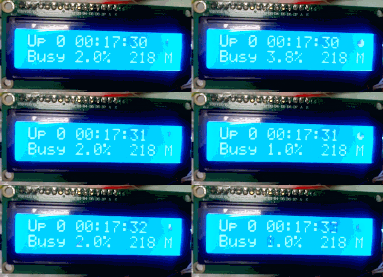
For this, the HD44780 driver was used and finalized. The LCD4Linux package is connected, in which a new display driver was also written that controls the display of the VT100 terminal commands, because the existing drivers did not fit.
Appearance: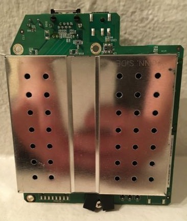
According to its characteristics, this board is not very bad:
Processor: APM82181Of the interfaces, there are SATA, a 100 Mbps network, a serial port (UART, not soldered), a place for the JTAG debugging connector. There was a label with the number 4061-705086-003 REV on the board. Ah. The number 4060-705086 is etched on the other side.
Frequency: 800 MHz
Platform: PowerPC 44x
RAM: 256 MB
ROM: 512 KV
Contents of the article:
1. Connecting the console
2. Download without disk
3. Compilation in LEDE
4. Port management (via LuCI and the console)
5. Connecting to the I2C bus
6. Connecting the PCF8574 port expander
The rest in the next part ...
Additions and comments are welcome. Go!
1. Connecting the console
To work with the board, you need to connect the console locally (although most operations after booting can also be done through SSH). This is done simply, there is enough information on the Internet, for example, here is the WD MyBook Live UART Port .
Pinout:
Connection is made to the RS232 port of the computer through the RS232-UART adapter, because logic levels on the board within 3.3V. The default baud rate is 115200.
After connecting and powering up, the console displays the u-boot bootloader:
U-Boot 2009.08-svn65645 (Oct 08 2012 - 14:36:50), Build: 0.2.5
CPU:   AMCC PowerPC  UNKNOWN (PVR=12c41c83) at 800 MHz (PLB=200, OPB=100, EBC=100 MHz)
       Bootstrap Option E - Boot ROM Location NOR/SRAM (8 bits)
       32 kB I-Cache 32 kB D-Cache
Board: Apollo-3G - APM82181 Board, 2*SATA, 1*USB
I2C:   ready
DRAM:  Auto calibration 256 MB
FLASH: 512 kB
DTT:   1 FAILED INIT
Net:   PHY EC1 Register: 0x2c8c
ppc_4xx_eth0
Type run flash_nfs to mount root filesystem over NFS
Hit any key to stop autoboot:  0
The message “Apollo-3G - APM82181 Board, 2 * SATA, 1 * USB” is a bit incorrect, since there is no USB, but only one SATA. This is due to the fact that the bootloader is common to MyBook Live and the DUO model with two disks.
If you do not click anything in the console, an attempt will be made to boot from the hard drive. In our case, it is not there, so the download is stopped by pressing any button.
2. Download without disk
The u-boot bootloader has many features for working with equipment.
For example, you can see all the colors of a three-color LED.
Turning off the LED (in the bootloader lights up in blue):
Test the three colors of the LEDs alternately:
ledtestoff Test the three colors of the LEDs alternately:
ledtestA list of commands can be seen by typing help. Learn more about the bootloader here . In the boot console, you can see that u-boot offers the option of mounting the nfs file system “Type run flash_nfs to mount root filesystem over NFS”. In this case, we will use another option - loading a RAM image from a TFTP server.
A server rises on the computer, for example TFTPD32 ( Official site ), then we configure the board. Set the local IP address and the address of the TFTP server (your computer). They must be from the same subnet:
setenv ipaddr '192.168.1.1'
setenv serverip '192.168.1.10'
View the names of the files that will be requested from the TFTP server:
=> printenv fdt_file bootfile
fdt_file=apollo3g.dtb
bootfile=uImage
Note that the variable fdt_file contains the name of the device tree file, and bootfile the name of the RAM disk image file with the operating system.
Names can be changed to more convenient ones, similar to addresses with the setenv command. After tuning, it is advisable to save the new values of the variables in the ROM:
=> saveenv
Saving Environment to Flash...
Un-Protected 1 sectors
Un-Protected 1 sectors
Erasing Flash...
. done
Erased 1 sectors
Writing to Flash... done
Protected 1 sectors
Protected 1 sectors
Thus, after rebooting or turning off the power, the settings will be saved. After that, we place the two necessary files (if you do not have them, then see the next section for their creation) on the TFTP server and type the command run net_nfs.
=> run net_nfs
Waiting for PHY auto negotiation to complete.. done
ENET Speed is 100 Mbps - FULL duplex connection (EMAC0)
Using ppc_4xx_eth0 device
TFTP from server 192.168.1.10; our IP address is 192.168.1.1
Filename 'uImage'.
Load address: 0x1000000
Loading: #################################################################
         #################################################################
         #################################################################
         #################################################################
         #################################################################
         #################################################################
         #################################################################
         #
done
Bytes transferred = 6680079 (65ee0f hex)
Using ppc_4xx_eth0 device
TFTP from server 192.168.1.10; our IP address is 192.168.1.1
Filename 'apollo3g.dtb'.
Load address: 0x1800000
Loading: ##
done
Bytes transferred = 16384 (4000 hex)
## Booting kernel from Legacy Image at 01000000 ...
   Image Name:   POWERPC LEDE Linux-4.4.21
   Image Type:   PowerPC Linux Kernel Image (gzip compressed)
   Data Size:    6680015 Bytes =  6.4 MB
   Load Address: 00000000
   Entry Point:  00000000
   Verifying Checksum ... OK
## Flattened Device Tree blob at 01800000
   Booting using the fdt blob at 0x1800000
   Uncompressing Kernel Image ... OK
   Loading Device Tree to 00ff9000, end 00ffffff ... OK
As you can see, two files are loaded as a result. They are located in the specified places in the RAM, the kernel is unpacked and loaded. As a result, we have a working system, in this case LEDE:
root@lede: uname -a
Linux lede 4.4.21 #0 Fri Nov 18 03:27:44 UTC 2016 ppc GNU/Linux
3. Compilation in LEDE
We will use LEDE as the source of the operating system for our board . This is a fork of OpenWRT and it supports the MyBook Live board. Download here: apm82181-lede . Download packages as written in the instructions:
./scripts/feeds update -a
./scripts/feeds install -a
Launch the configurator:
make menuconfigWe select “AppliedMicro APM821xx” as a system (“Target System”), “Devices which boot from SATA (NAS)” as a subsystem (“Subtarget”), and “Western Digital My Book Live” as a profile (“Target System”) . In the final image (“Target Images”), ramdisk must be marked.
We choose packages at our discretion. After saving the settings in the configurator and exiting it, you can start compilation with the make command.
After the end of the process, if it went without errors, the necessary files can be picked up and put on the TFTP server:
- rename the file bin / targets / apm821xx / sata / lede-apm821xx-sata-MyBookLiveSingle-initramfs-kernel.bin to uImage
- rename the file build_dir / target-powerpc_464fp_musl-1.1.15 / linux-apm821xx_sata / tmp / lede-apm821xx-sata-MyBookLiveSingle-initramfs-kernel.bin.dtb to apollo3g.dtb
Thus, we went through the stages of booting a system without a disk.
4. Port management (via LuCI and console)
I could not find the circuit of this board and generally the circuit of any device based on the APM82181 processor on the Internet. Therefore, we will partially reverse engineer (reverse engineer), that is, guess about the connections on the board and verify this. LEDE developers apparently partially did this, because the connected ports can be seen in the device tree or see information from the kernel:
Input / output ports
root@lede: cat /sys/kernel/debug/gpio
GPIOs 496-503, platform/4e0100000.gpio1, 4e0100000.gpio1:
 gpio-498 (                    |Reset button        ) in  hi
GPIOs 504-511, platform/4e0000000.gpio0, 4e0000000.gpio0:
 gpio-504 (                    |enable EMAC PHY     ) out hi
 gpio-505 (                    |Enable Reset Button,) out lo
 gpio-506 (                    |Power USB Core      ) out hi
 gpio-507 (                    |Power Drive Port 1  ) out hi
 gpio-508 (                    |?                   ) out lo
 gpio-509 (                    |?                   ) out hi
 gpio-510 (                    |?                   ) out lo
 gpio-511 (                    |Power Drive Port 0  ) out hi
As you can see, one port is used to enter a button press, the rest to an output for control. It is clear that by editing the device tree file (file with the .dts extension), any port in the operating system can be freed from functions, but this may affect the functionality of the functional blocks of the board. Except for the LED. Ports connected to this indicator can be used for their own purposes. The ports indicated by the question mark are connected to it. And LED control is available, for example, from the console.
By default, after loading, the LEDE indicator lights up in green. So you can turn it off:
echo 0 > /sys/class/leds/mbl\:green\:power/brightnessAnd turn on the blue:
echo 1 > /sys/class/leds/mbl\:blue\:power/brightnessIf LEDE was built with the LuCI web shell, then the LEDs can be controlled from a browser.
Go to the IP address of the network card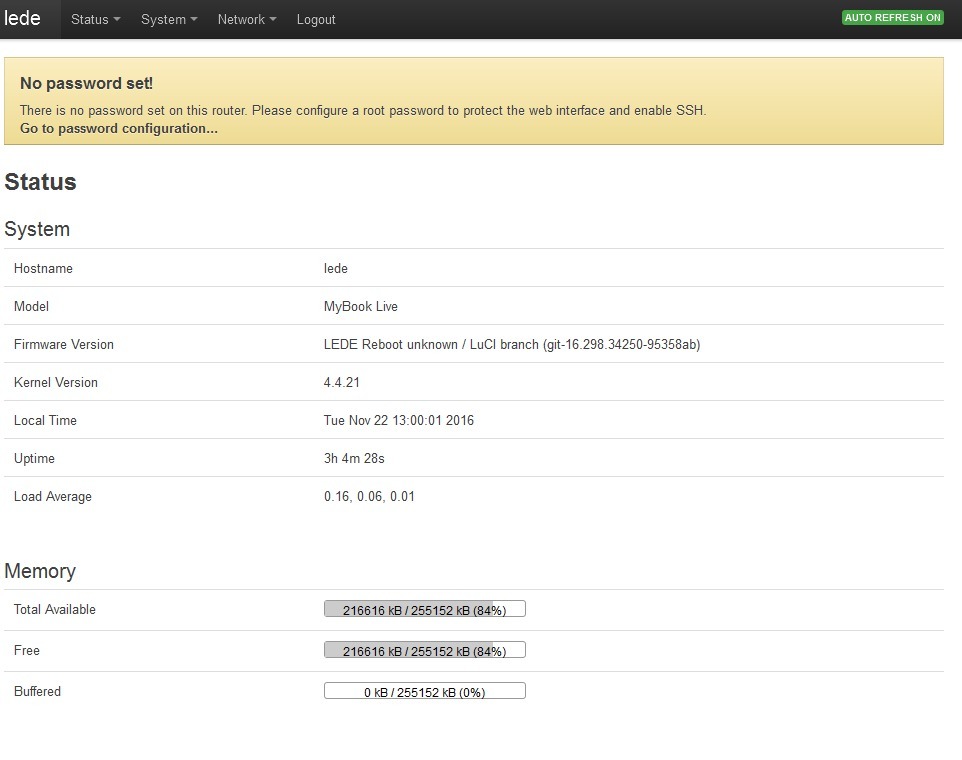
In the System menu, go to LED Configuration, and configure what events each particular LED color triggers. For example, like this, the green LED will blink on incoming and outgoing network packets:
Network activity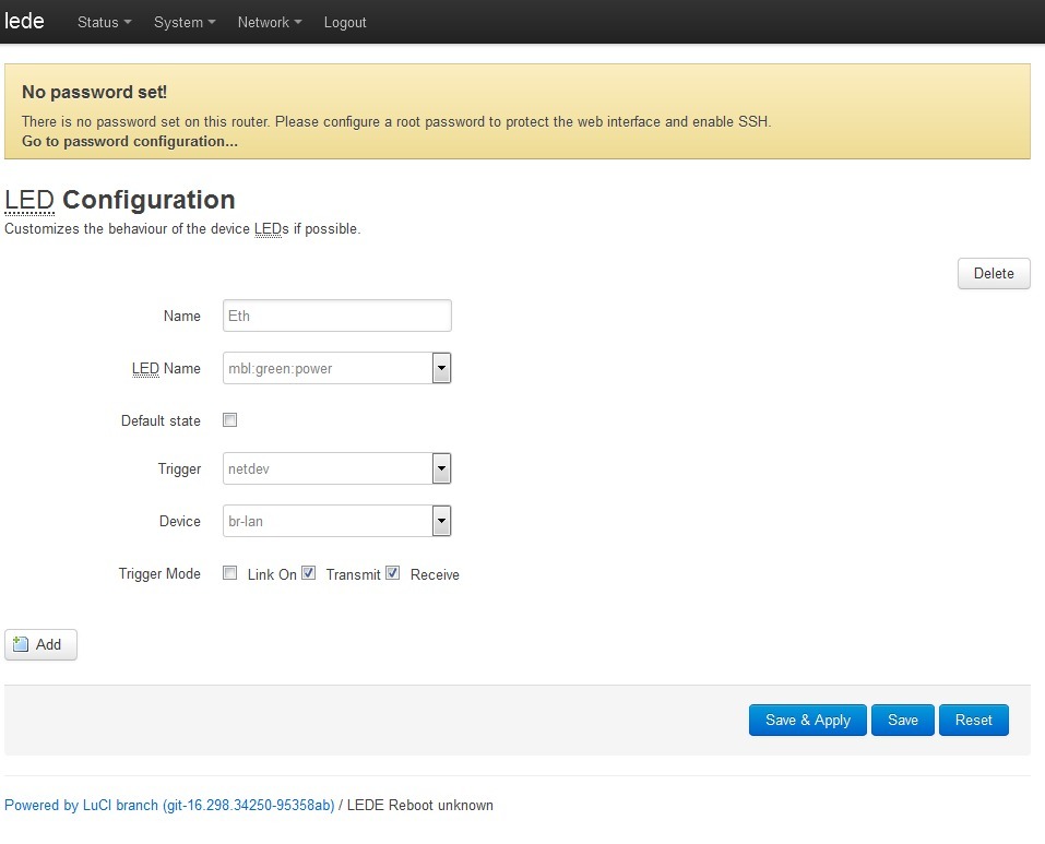
It is clear that if you use the LED ports for your needs, then the service that controls the LED (/etc/init.d/led) will not need a driver either. And control can be made from a script like this:
echo 1 > /sys/class/gpio/gpio508/value5. Connection to the I2C bus
So, it is possible to use at least three ports. Of course, I would like to have more resources. You can put a port expander on these ports and connect it to the I2C software port. Then you can dial an almost unlimited number of ports, though with a low speed.
There were a number of empty seats on the board, there was a desire to check if something was divorced from them, which might be useful to us.
For example, near the processor, a seat marked U12 for a chip with 8 legs:
Soldered cable
After making sure that all the contacts had no more than 3.3V, a digital analyzer was connected.
During the boot process, no signals were detected. Then, the I2C bus description was added to the device tree, since it was initially absent:
IIC0: i2c@ef600700 {
  compatible = "ibm,iic";
  reg = <0xef600700 0x00000014>;
  interrupt-parent = <&UIC0>;
  interrupts = <0x2 0x4>;
  fast-mode;
  #address-cells = <1>;
  #size-cells = <0>;
};
It is clear that in the LEDE configuration, it is also necessary to enable I2C support in the core (kmod-i2c-core).
After compiling, updating the file on the TFTP server and rebooting, the device / dev / i2c-0 appeared.
root@lede: dmesg | grep i2c
[    4.816060] i2c /dev entries driver
[    4.819878] ibm-iic 4ef600700.i2c: using standard (100 kHz) mode
By sending characters with the echo command:
root@lede: echo 11 > /dev/i2c-0
ash: write error: Remote I/O error
A signal was detected by a digital analyzer:
Thus, the I2C hardware bus was found, which greatly expanded the I / O capabilities of this board.
Judging by the location of the signals on U12 (5 - GND, 7 - SDA, 8 - SCL), this was probably assumed to be the ADM1032ARMZ - temperature sensor.
6. Connecting the PCF8574 port expander
It's time to connect something to the I2C bus. In stocks there was a liquid crystal indicator measuring 2x16 familiarity, each 8x5 pixels. Made in China based on the HD44780 controller clone and PCF8574 port expander.
LCD HD44780 16x2 I2C
According to the description, it allows power and signal levels of both 5 and 3.3V, but when checking, a very low image contrast was found with 3.3V power. Since 5V power would also lead to signal levels from 0 to 5 V, and the board is designed for 3.3, we had to make a primitive signal level converter. The I2C bus is bidirectional, a confirmation signal must be received from the device, so at least a bi-directional converter must be on the SDA line. Very well circuit options are described here: Matching the logic levels of 5V and 3.3V devices . In our case, it was used
insulated gate field effect transistor circuit,
True, the transistor is different, selected from similar ones - BSS123.
Assembled on a breadboard:
Thus, 5V power is supplied to the LCD indicator (taken on the board from the SATA power connector), both power supplies come to the level converter - 3.3 and 5V.
Now add a port expander to LEDE. We enable kernel support (Kernel modules - Other modules - kmod-gpio-pcf857x ... PCX857x, PCA967x and MAX732X I2C GPIO expanders), recompile, upload to the server, and reboot.
We look for the presence of a driver:
root@lede: lsmod |grep pcf
gpio_pcf857x            6128  0
We connect (0x27 - the address of our expander on the I2C bus):
root@lede: echo pcf8574 0x27 > /sys/bus/i2c/devices/i2c-0/new_device
[  218.957888] pcf857x 0-0027: probed
[  218.961321] i2c i2c-0: new_device: Instantiated device pcf8574 at 0x27
Check the appearance of the ports:
root@lede: ls -l /sys/class/gpio/
--w-------    1 root     root          4096 Jan  1  1970 export
lrwxrwxrwx    1 root     root             0 Nov 25 04:04 gpiochip488 -> ../../devices/platform/plb/plb:opb/4ef600700.i2c/i2c-0/0-0027/gpio/gpiochip488
lrwxrwxrwx    1 root     root             0 Jan  1  1970 gpiochip496 -> ../../devices_platform/plb/plb:opb/4e0100000.gpio1/gpio/gpiochip496
lrwxrwxrwx    1 root     root             0 Jan  1  1970 gpiochip504 -> ../../devices/platform/plb/plb:opb/4e0000000.gpio0/gpio/gpiochip504
--w-------    1 root     root          4096 Jan  1  1970 unexport
As you can see, a group of gpiochip488 ports appeared on the I2C bus with the address 0x27. Now you can add ports, which will also be represented by the system, as well as those located on the processor, despite the fact that they work through the port expander:
root@lede: echo 488 > /sys/class/gpio/export
root@lede: echo 489 > /sys/class/gpio/export
root@lede: echo 490 > /sys/class/gpio/export
root@lede: echo 491 > /sys/class/gpio/export
... and so on to 495, since we have an 8-port expander available. Check their availability:
root@lede: ls -l /sys/class/gpio/gpio???
lrwxrwxrwx    1 root     root             0 Nov 25 04:17 /sys/class/gpio/gpio488 -> ../../devices/platform/plb/plb:opb/4ef600700.i2c/i2c-0/0-0027/gpio/gpio488
lrwxrwxrwx    1 root     root             0 Nov 25 04:17 /sys/class/gpio/gpio489 -> ../../devices/platform/plb/plb:opb/4ef600700.i2c/i2c-0/0-0027/gpio/gpio489
lrwxrwxrwx    1 root     root             0 Nov 25 04:17 /sys/class/gpio/gpio490 -> ../../devices/platform/plb/plb:opb/4ef600700.i2c/i2c-0/0-0027/gpio/gpio490
lrwxrwxrwx    1 root     root             0 Nov 25 04:17 /sys/class/gpio/gpio491 -> ../../devices/platform/plb/plb:opb/4ef600700.i2c/i2c-0/0-0027/gpio/gpio491
We set the direction of work to the conclusion:
root@lede: echo out > /sys/class/gpio/gpio488/direction
root@lede: echo out > /sys/class/gpio/gpio489/direction
root@lede: echo out > /sys/class/gpio/gpio490/direction
root@lede: echo out > /sys/class/gpio/gpio491/direction
If you need to enter, then you need to give the command "in". Well, check how the output works, for example by measuring the output status with a tester or digital analyzer. In the case of an HD447880 LCD connected to the expander, you can take advantage of the fact that the third bit of the expander controls the backlight of the indicator:
root@lede: echo 1 > /sys/class/gpio/gpio491/value
root@lede: echo 0 > /sys/class/gpio/gpio491/value
The first command turns on the backlight, the second turns it off. To add devices during the boot process, you can include them in the device tree:
			IIC0: i2c@ef600700 {
				compatible = "ibm,iic";
				reg = <0xef600700 0x00000014>;
				interrupt-parent = <&UIC0>;
				interrupts = <0x2 0x4>;
				fast-mode;
				#address-cells = <1>;
				#size-cells = <0>;
				/* Boot ROM is at 0x52-0x53, do not touch */
				/* Unknown chip at 0x6e, not sure what it is */
				i2cled: led@27{
					#gpio-cells = <2>;
					compatible = "nxp,pcf8574";
					reg = <0x27>;
					gpio-controller;
				};
			};
The lines after the i2cled label replace the command "echo pcf8574 0x27> / sys / bus / i2c / devices / i2c-0 / new_device".
So, the opportunity to transparently use I / O ports connected through an expander to the I2C bus appeared and is implemented in practice.
For the first part, probably enough. In the second part, unless of course there is an obvious antagonism in the comments, we get to using the indicator to display the status of the system:
For this, the HD44780 driver was used and finalized. The LCD4Linux package is connected, in which a new display driver was also written that controls the display of the VT100 terminal commands, because the existing drivers did not fit.