Texas Instruments TI-99 / 4a Computer Architecture and Programming
The Texas Instruments TI-99 / 4a computer is almost unknown outside the United States, but it was very popular there (more than two million cars were produced). Although this computer was created as a home one, an essential feature (which determined its architecture in many respects, and then fate) was that it was based on the already existing serious mini-computer TI-990 , assembled using ordinary TTL logic. In fact, the TMS9900 microprocessor in the TI99 / 4A computer is an implementation of the TI-990, but in the form of a chip. The TI-990 was launched in 1975, and the TMS9900 in 1976.
 Thus, TI99 / 4a (a slightly simpler TI-99/4 was released in 1979, and already TI-99 / 4a in 1981) inherited an extremely strange architecture for home computers. Firstly, the TMS9900 microprocessor in it is 16-bit - with an honest 16-bit data bus (this is in the late 1970s!). Secondly, there are no registers on the chip (except for PC, flags and the WP "register" pointer). What can be called registers is located in a separate 16-bit static RAM chip with a size of 256 bytes and can be addressed simultaneously as memory and (first 16 words) as R0..R15 registers. It's called a scratchpad.
There is no hardware stack, instead, saving values when calling subprograms is done by changing the pointer to the beginning of the WP registers in this RAM itself (it resembles register windows in Sparc). In the ancestor (TI-990), it was also used to switch context when implementing multitasking.
Although the TMS9900 clock frequency is 3 MHz, the instructions take up quite a few clock cycles - at least 8. Even multiplication and division are implemented (124 clock cycles).
 Everything except the processor, alas, is more ascetic. In addition to the tiny static RAM mentioned, there is also video memory - 16kb of slow 8-bit DRAM, which is accessed through a video controller.
In other words, without additional peripherals, the TI99 / 4A is a 16-bit computer with 256 bytes of RAM, built-in BASIC ROMs and cartridge programs (they have up to 8kb of honestly addressed ROMs or more, with different tricks).
It is impossible to load a normal program into a bare computer even from a cassette, because there is no RAM for this (256 bytes are not counted, and the rest is video memory).
Therefore, the minimum adequate computer configuration is PEB (Peripheral Expansion Box) - a special large basket for expansion cards, a drive and a 32kb memory extension. Or NanoPEB - a modern device that includes all of the above.
For PEB / NanoPEB, you also need an Editor / Assembler cartridge (without which you can only download and run programs on BASIC and which at the same time contains the mentioned additional 32kb of RAM).
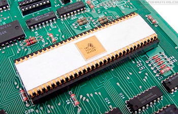 The TMS9918 video controller (also used in MSX and ColecoVision) supports graphic (256x192, 15 colors) and text modes, allows you to change the character generator, can display 32 hardware sprites 8x8 and 16x16 at the same time (true, no more than four pieces can be in one line at a time).
Sound is output through TMS9919 (its analogue, SN76489, was used in IBM PCjr, BBC Micro, ColecoVision, some Sega consoles):
4 channels (three rectangle generators and one noise), 16 volume levels.
It is believed that such an uneven in terms of bit depth and sometimes awkward architecture was obtained due to the fact that the 8-bit version of the TMS9900 processor (TMS9985) was not ready at the time.
As for the software, the TI99 / 4A was intended for educational purposes (in fact, as opposed to Atari and Commodore). Together with the oddities of architecture described above, this has led to very few good games (if any). The fact that the computer was distributed exclusively in the USA added to this the absence of a demoscene (my 99tro intro was, it seems, the second on this platform).
As already mentioned, little can be done with the bare TI99 / 4a, unless you can start something from the cartridges (if any). The PEB expansion basket required for normal operation is very expensive and takes up a lot of space. Since historically it turned out that all the serious development and, in general, any actions with TI were tied to the very PEB, modern fans of the machine went the way of emulating it (even nobody seems to bother with the emulator of ROM cartridges).
A modern substitute for PEB is NanoPEB . With some patience, it can be found on ebay or from individual sellers for 50 ... 80e.
This device sticks into the right port of the computer (the same place as the speech synthesizer. Including you can stick it through the synthesizer) and emulates 32kb of additional RAM, three drives (on a CompactFlash card) and an RS-232 port.
There is also a CF7 + device in which everything is the same, but instead of RS-232 there is a parallel Centronics port.
By itself, the presence of NanoPEB allows you to download only programs on BASIC (and from the standard TI BASIC it is impossible to run the program in machine codes, except for completely dirty and non-trivial hacks).
Therefore, the Editor / Assembler (EA) cartridge, stuck in the top port, is absolutely necessary. With it you can already download and run normal programs. The cartridge is also searched on ebay. It seems that you can use the cartridge Extended Basic (XB) instead.
To transfer programs to the CompactFlash card, you must use special utilities. The most popular is ti99dir (for Windows).
It is worth mentioning the F18A project - the implementation of the TMS9918A video controller on FPGA, with a number of additions. Those. the video chip in the usual TI-99 / 4a is replaced with a new one, while all the old software goes as before, but it is possible to display the image on a VGA monitor, set previously inaccessible video modes, etc.
In addition to Basic programs, which we will not talk about, there are two main formats in which a program can be represented in machine codes - for loading from a disk through Editor / Assembler and for a cartridge.
Files downloaded via EA are called EA3 (because in Editor / Assembler you need to select the third menu item - “LOAD AND RUN” to download them). They can be launched in any memory area (i.e., EA performs a link upon loading). For the emulator, such files are stored on a disk image (.DSK) and have a format of Dis / Fix 80.
Also, less often, memory image files called EA5 can come across (they are loaded into EA by selecting the fifth menu item - “RUN PROGRAM FILE”). These are already linked files tied to memory addresses. The emulator is also stored in disk images as "Program".
Downloading from a program disc in codes without fail requires the cartridge Editor / Assembler (or an analogue).
Programs for cartridges are rigidly tied to addresses and are just a binary that is flashed into ROM (for emulators, this is the .RPK format, less commonly - .BIN).
There are two substantially different approaches to writing assembly language programs. The first is the use of so-called GPL language. This is a cross between Extended Basic (XB) and Assembler, both in terms of performance and capabilities. Those. for all, the routines existing in the ROM are heavily used and, importantly, interrupts must be enabled.
The second option is assembler, which will be discussed.
The main unusual feature of the TI-99 / 4A is, in fact, in the TMS9900 processor. From the majority of processors that were used in home computers of that time, it is distinguished by the following:
Physically, the processor has only three registers - ST (flags), PC (command pointer) and WP (workspace pointer). Registers R0-R15 are located in the static RAM outside the chip. The address from which they start is stored in the WP register and can be changed. Usually it is set to> 8300 (the sign ">" means the hexadecimal system, the sign ":" - binary).
From> 8300 to> 83FF, there are 256 bytes of static 16-bit RAM called “scratchpad”.
Working with it is about 2 times faster than with the rest of the dynamic 8-bit (standard extension 32kb).
There are many addressing modes, and with one command you can, for example, transfer a value from a memory cell to another, changing it at the same time.
There is no stack in the processor - it is supposed to use the mapping of registers to any memory area with the LWPI addr command to save and restore the context.
The subprograms are called by the BL ADDR command , which puts the next address after it into the R11 register. Accordingly, B * R11 (aka RT) is used to return. There is also BLWP, which preserves workspace in addition to the return address (but at the same time slow).
Usually the first thing to do is turn off all interrupts and set the beginning of the registers to the beginning of the static RAM. Therefore, the procurement program looks like this:
Because of this register architecture, programming features appear. Namely:
1. Registers can be accessed not only as R1, R2, etc., but (since they are in the address space) and as memory cells. This, in particular, allows you to work separately with the low and high bytes of the register, which for this are predefined by constants:
However, it is clear that it is far from always possible in a command to simply replace the register with memory (for this command, the desired addressing mode may simply not be available).
On the other hand, it is still necessary, because there are few commands working with halves of registers (MOVB, SWPB, AB, SB, some logic).
Of course, regardless of the currently installed workspace, there is always access to any register in any workspace (at the corresponding address in memory).
2. Since there is no stack (sometimes, however, it is simulated programmatically), saving and restoring registers is done by switching workspace. If you use this intensively, the available 256 bytes of fast SRAM will end quickly - they are always missing.
To show what the code for the TMS9900 looks like, a small example is Hello World:
This is a modern (not quite traditional) assembler TMS9900. Initially, in addition to the absence of colons after the marks, the registers were written not as R with a digit, but as a simple digit. Those. LI 4.5 and MOV 7.8 in the old assembler are LI R4.5 and MOV R7, R8 in the new.
It is easy to see that this did not add much to readability, so now they write R (although even modern assemblers understand the old version of the record). Some people, however, interfere with both syntaxes. As a result, in the same source code you can find a number of mnemonics SLA R5,0 (shift R5 to the left by the number of bits from the register R0) and SLA R5,1 (shift R5 to the left by _one_ bit).
Some (medical :) interest is in command X, which executes an instruction whose code is passed to it as a parameter.
It is believed that X can be used for debugging purposes, as well as for navigating tablets. Well, in any situations where you need a self-modifying code.
As for ROMs, TI-99 / 4a uses the so-called GROMs. They are not mapped entirely to the address space of the processor, and data is accessed sequentially - the start address of the data is entered in GROM at a special address and then data is read from another special address from there. In this case, the current address of the GROM data increases automatically, with each reading.
Printing a string of characters from GROM
To output graphics and text, the TDP-99 / 4a is equipped with the VDP TMS9918a video chip, which is also used in MSX1 and ColecoVision .
VDP allows you to display graphics with a resolution of 256x192 in 15 not very successful colors (+1 transparent, through which the background shines through) and monochrome sprites - 32 pieces of the same size 8x8 or 16x16 with a significant limitation: no more than 4 sprites on one line.
In VDP 16kb DRAM and it is distributed between graphics (text), colors and sprites.
Video memory does not map to the address space of the processor. To write to it, you must first enter the starting address in the video memory at which the address will be recorded at a specific address, and then write the necessary values in a row to another address (one). In this case, each subsequent value will appear in the video memory at the address increasing by one.
Depending on the video mode and memory allocation, you can choose the optimal mode in terms of addressing convenience, memory used and the number of colors (in the pixel block). At its core, all modes are text. In the sense that in all cases there is the concept of “characters” that can be placed in different places on the screen and which can be changed. But, since it is possible to reprogram the characters so that their appearance matches their code, in fact the mode is already "graphic". However, this is typical of many 1980s video controllers. Even in the relatively modern VGA there was such an opportunity (the author used it to implement the 640x400 fast mode with separate memory for colors).
Most often, TI uses Graphic Mode I (it is in this mode that the computer appears when it is turned on and initialized). In it, you can set two colors (background and image) per 8x8 block. Total blocks 32x24. The only advantage of this mode is the relatively high speed of color changes.
There is also a Multicolor mode - a graphic mode with a resolution of 64x48, where a color is set for each large pixel (but with this resolution, unless you draw some kind of plasma or ANSI art) and a couple of purely text modes 40x24 characters - color and monochrome.
The most powerful and interesting mode in VDP is the so-called Graphic Mode II (aka “bitmap mode”). This mode allows you to use two colors (background and image) inside an 8x1 pixel block. In other words, 2 colors for every 8 horizontal pixels. Unfortunately, the order of blocks (that of pixels, what of their colors) is extremely inconvenient for everything except character output - bytes go from top to bottom 0-8, then the next to the right again from top to bottom 8-15, etc. to the right edge. Then everything repeats again from left to right.
When setting the mode, addresses for the attributes (Color Table), bitmap (Pattern), the order of the characters that form the blocks for the bitmap (Name table), data for sprites (Sprites data) and attributes of sprites (Sprites Attributes) are also set. You can not set any addresses - there are just a few options that you should choose so that as a result, without overlapping, all 16384 bytes of video memory are rationally used. For example, for my intro “99tro” I allocated the memory like this (Graphics Mode II):
Sprites can be of two sizes - 8x8 or 16x16 (all sprites switch at once) and you can additionally stretch them (also all at once) twice.
The total number of sprites is displayed simultaneously on screen 32 (but no more than 4 in one line). At the same time, 2kb of memory for Sprite patterns is enough for two sets of 32 16x16 sprites.
Individually for each sprite, you can set the following parameters (through the Sprite attrubutes area, for each byte in the series):
The lack of direct addressing of video memory in combination with its unsuccessful organization and the absence of transfer instructions in the processor for more than a byte at a time does not allow it to be updated quickly. For example, the implementation of horizontal smooth scrolling of the 256x8 pixel region while playing VGM music in parallel almost completely takes the time of the beam backward movement in the frame. Those. there’s almost no more time left.
In games (modern), this problem is solved in rather cunning ways, when when scrolling, not the entire scrolling area is updated, but only requiring changes. Accordingly, the contents of the screen are thought out in such a way that there is a minimum of these changes. Graphics Mode I is also commonly used with a lower color resolution (two colors per 8x8 block).
As in many other systems, in TI-99 / 4a it is highly desirable to render the image fit into the vertical retrace of the beam. To do this, VDP generates an appropriate interrupt - at the beginning of drawing the bottom of the frame.
 There are the following options:
1. Interrupts can be disabled completely (LIMI 0 + instruction specifically for VDP - setting the corresponding bit in register 1). In this case, everything will be faster, but it will not work to track the reverse beam in any way.
2. Switch on interruptions completely (LIMI 2 and in VDP). Then you can hang your own interrupt handler that will do something.
3. Enable interrupts in VDP, but disable them with the LIMI 0 instruction. In this case, no handlers will be called, but you can manually monitor the beam backward by checking the bit in the VDP status register (after reading the register, this bit is automatically reset. If it is not reset, then the next interrupt will not be generated).
A fairly typical scheme is when interrupts from VDP are turned on, general ones are turned off (LIMI 0), but in the main loop they are turned on (LIMI 2) for a short period of time, so that a processor that hangs on an interrupt (for example, playing music) sometimes gets control.
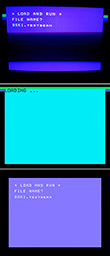
Not all emulators correctly mimic this interrupt. But, say, MESS does this more or less adequately. In the picture you can see a simple test - the color of the frame changes with some delay relative to the vertical retrace (on the real TI and on two emulators - MESS and js99er).
For receiving music and sound effects, a TMS9919 chip is installed in the TI-99 / 4a (analogs: SN76489, SN76496). It is quite simple: three independent tone generators and one noise generator. 15 volume levels.
Since this is a fairly popular chip (used in some consoles, in IBM PCjr / Tandy-1000, etc.), there is a lot of information on it.
For TI-99 / 4a, there is a MOD2PSG tracker (it normally starts under Win7 64bit). In particular, it allows you to download psgmod files and export vgm and epsgmod.
There are two working players - EPSGMOD Player by Tursi (requires data in epsgmod format, hangs its handler to interrupt VDP).
It is connected as follows:
With this connection of the player, it is necessary to remove REF and END from its sources (since they are oriented to use with traditional assembler).
Note that in the main loop, interrupts are activated for a moment (limi 2). This is necessary for the player to work, which works by interrupting the VDP from the reverse beam (occurring every 1/60 second). In this case, the SGTICK subroutine of the player is called.
Accordingly, it is important that for NTSC the computer version and the music must also be NTSC (the frame rate must match).
The second player (of the same author) plays VGM format files (also includes the VGMComp utility for VGM compression). This handler does not hang up, you need to call it manually with a frequency of 60Hz.
It looks like this:
In my opinion, the second version of the player has better quality (although it may depend on specific music) and manual call is more flexible than a handler (which you yourself can hang, if you really need to) - you do not need to enable interrupts.
He also has a 30Hz player option. At the same time, it must also be called at a frequency of 60 Hz, but it will be used every second call. Accordingly, the processor load is reduced, but the sound quality of the music can potentially drop (depending on the effects used in it).
Apparently, there is a bug in the player (or when exporting to VGM) that creates incomprehensible problems with looping music.
 Since the speech synthesizer is a very popular peripheral for the TI-99 / 4a, quite a few programs use it. The synthesizer attaches to the port on the right side of the computer (if you have NanoPEB, you can plug it directly into the synthesizer). Inside is a ROM with data for words, an LPC decoder (TMS5220), and a DAC.
There are two operating modes. In the first, the computer tells the synthesizer which words from the ROM should be pronounced (there are few words there). In the second (Speak-External), it is possible to transfer directly compressed LPC data, which the synthesizer will simply reproduce. For data packaging, the ancient QBox Pro program is used, which runs under WinXP (the process is shown here ).
The synthesizer can be controlled directly from the assembler program. If you just want to play around, then you need a cartridge - for example, Speech Editor (allows you to pronounce the typed text, and also adds commands to play words in the standard Basic). The Terminal Emulator cartridge allows you to pronounce individual phonemes and combine them into arbitrary words.
In the most famous emulators, the synthesizer is supported. It is believed that the best support (the hardware is fully emulated) is implemented in MESS / MAME.
Below is an example that pronounces the word "HELLO" taking LPC data from the ROM of the synthesizer. The documentation indicates that status checking is not possible if the code is running in RAM on an 8 bit bus (i.e. it is required that the code is on a 16 bit scratchpad), however, after checking on emulators and a real computer, I consider this to be reinsurance (probably like and in the case of VDP, all these requirements relate to some very early versions of iron). The result is such a short code:
The addresses of all the words from the ROM can be found in the book Editor Assembler Manual.
If you want to play arbitrary speech converted to LPC using QBox Pro, then in the simplest case, the code will look like this:
For QBox Pro you need to prepare a wav file with a speech. A clear male speech will sound best. One phrase will occupy about a kilobyte.
Passing singing or sheet music will not work. After coding in LPC, such sounds will be completely unrecognizable.
Settings and operations in QBox Pro:
Result: test.sfm
To develop and test programs on a PC, and then download them to TI-99 / 4a, you need the following:
Hardware:
- PC / Win7 (64bit is suitable)
- TI-99 / 4a
- Cartridge Editor / Assembler (or any other that allows you to download and run programs in machine codes)
- NanoPEB or CF7 + (for emulating a drive and loading a program from a CompactFlash card into TI-99 / 4a)
Software:
- One of the many TI-99 / 4a emulators is MESS / MAME or js99er (or better, several )
- The xdt99 package, which includes assembler and utilities for working with files and disk images (in particular, xvm99 for writing a disk image to a CompactFlash card, in the format needed for NanoPEB)
Organization of the process:
Programs for a cartridge and for loading from a disk are two different things. Not only in format (RPK and DSK), but also in terms of working with memory (the second option pauses the 32kb memory extension). If there is a goal in the end to run the code on a real machine, you need to focus on the disk version. We will consider it.
Emulators are significantly different from each other, it is very difficult to name the best. This is not only a question of the quality of emulation, but also the convenience / simplicity of launching a finished program.
The most famous: mess (mame), js99er, v9t9, classic99.
All of them are not perfect. It is quite possible to expect a 10% difference in speed between the emulator and the real piece of hardware (specifically, I observed that mess and js99er execute all the code a little faster than the real TI. In the same NTSC)
When using xdt99 as an assembler, the process looks like this:
The -R option allows you to properly name registers in the source text (r0, r1, ...). In the traditional TMS9900 assembler, registers in commands are written simply in numbers, which introduces wild confusion.
Keep in mind that the object file is a text file with hexadecimal codes inside. Although this is not a final binary file, nevertheless, due to the peculiarities of downloading programs on TI-99 / 4a (via Editor / Assembler), it is often considered a ready-made program. All the more convenient because it is usually not tied to a specific area of memory at boot time.
If the final binary is required, add the -i option for xas99. Then it will be necessary to load it not through point 3, but through point 5 in the Editor / Assembler. If you need a final binary file of more than 8k, without splitting into separate parts, instead of -i you need to use -b.
Additionally, you can get the .lst listing file by specifying the -L option.
A special cartridge image for automatic loading simplifies the work somewhat (see "jumpstarting" in the xdt99 documentation). The image allows you to do without the Editor / Assembler in the emulator, pressing buttons in it and entering the file name. The finished code is loaded from the disk automatically when you select a cartridge. For example, mess (mame) in this case starts like this:
If you need a debugger, you can also add -debug (entering the debugger from the emulator, provided that the option was specified - with the `key)
The parameter" ti99_4a "replaces the NTSC version of the computer (ie the most common). For the PAL version, this will be ti99_4ae.
The difference is very significant, at least because of the different frame rates. in the first case, personnel 60Hz, in the second 50Hz. Wrong choices can lead, for example, to slow-down music playback (if it was written under NTSC and PAL is selected).
If the application you are developing is significant in size or if something takes noticeable time, you can speed up the emulation with the -speed 20 option.
You can use xvm99.py to transfer a program record to CompactFlash in NanoPEB format
Make sure that on your computer PHYSICALDRIVE2 corresponds to the device in which the CF is inserted (otherwise you can spoil the data on your disks!). On Windows, this can be viewed with the command
Since there can be several images on one CF to emulate several drives, the second parameter corresponds to the drive - i.e. DSK1 for 1).
Preliminary it is recommended to format CF under FAT16, after which it is mandatory to type “call format (1)” on TI itself with NanoPEB inserted from TI Basic, where 1 is the number of the formatted virtual drive.
View flash drive content:
When loading a program on TI itself, you need to insert a cartridge with Editor / Assembler and NanoPEB. Turn on NanoPEB, then the computer. In the menu, select option "2" - "Editor / Assembler", in it item 3 (or 5), type DSK1.FILENAME and press ENTER.
Case in the file name is important.
In the process of studying TI-99 / 4a, I wrote “99tro” (source) - a small invitation intro at Chaos Constructions'2016, presented at Revision'2016. In addition to its source code (the code is very terrible - do not write it like that!) Some explanations will be given here.
The main idea is for the intro to convey the style of the old cracktro for the Commodore 64, if possible, naturally adjusted for the more modest capabilities of the TI-99 / 4a video and audio chips. Roughly speaking, I wanted something like a color logo, a smoothly scrolling text line, iridescent colored stripes and a dangling inscription from sprites.
 Soon, the following significant limitations and shortcomings of the computer became clear:
- There is no hardware scrolling, it can only be done by shifting and rewriting video memory
- Exchange with video memory (this also applies to sprites and graphics and text) is very slow and the relatively high processor frequency does not save (as well as its 16-bit, because exchange with VDP goes on the 8-bit bus).
- VDP has a number of undocumented or inaudibly documented bugs (which is not surprising, TMS9918 is one of the first specialized video chips). A couple of times this led to the fact that the already almost finished part had to be abandoned.
- Very limited functionality of sprites - only 4 per line (which automatically means that you can’t do anything wide with sprites on the screen), monochrome, a large number of processor instructions for a simple change of color or coordinate of the sprite.
- Playing music (vgm) takes a very substantial processor time. As stated in the source code of the player from Tursi, this is 2-20% for the 30Hz version, depending on the specific music. In my particular case, at least 10-15% was obtained.
- The trouble is with convenient debuggers (in fact, the same picture was with the Vectrex emulator - in both cases there are powerful debuggers, but inconvenient so that, in fact, their use is more likely to slow down than to speed up)
- Inability to quickly check the code for real iron. To do this, turn everything off, remove the USB flash drive, insert it into the PC, copy the code onto it, remove it from the PC and paste it into TI, turn on the disk emulator and TI itself, select Editor / Assembler, select the program load point, type DSK1.program_name, press ENTER Wait for download (about a minute).
As a result, gradually, only what was allowed to implement the piece of iron was left from the previous ideas (of course, taking into account that this was my first program for this platform and this processor):
- CHAOS CONSTRUCTIONS'2016 inscription / logo with the robot head
- Flashing to the beat of music eyes and mouth of the robot
- Appearing letter by letter, following the pulsating cursor, text in several lines
- Smoothly scrolling text line
- Background music (vgm)
In order to somehow use the strengths of TI-99 / 4a, I chose the mode with the maximum graphic and color resolution - Graphics mode II (Bitmap). For games it is used extremely rarely, because it requires all 16kb of video memory and, accordingly, is very slow in terms of updating the image.
However, unlike games, in my case it was possible to go for a trick (which is generally characteristic of demo and intro) - I did not dynamically update the colors at all anywhere else. Everything related to flowers was established only once at the beginning, outside the main cycle.
In the cycle, only bitmap changed and two sprites switched.
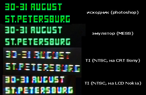 The upper logo was first drawn in Photoshop, then converted to a video memory dump for VDP using the Convert9918 utility, and then these two steps were cyclically repeated - i.e. Refinements were made to the original image so that after conversion (in 15 rather curved colors and color resolution 2 colors by 8 horizontal pixels) it would look as adequate as possible. I must say that the distortions characteristic of the composite NTSC signal played, as often happens in such cases, on the hand - on the CRT monitor the picture looks clearly better than in the emulator (besides, it is warmer and lighter).
I must say, for the first time I seriously realized how important the correct choice of 16 possible colors of its (platform) developers is for the success of the platform. In the case of TI-99 / 4a, these colors are extremely unsuccessful (in addition, there are 15 of them).
In addition, for the first time I had to deal with the problem of color coding in an NTSC video signal. The photo shows what the colors for single pixels turn into (in PAL, this also causes problems, but incomparably smaller).
The bottom smooth scrolling was taken from a single similar example (Matthew Hagerty) and modified. Honestly. for such a short time I could hardly penetrate the TMS9900 assembler deep enough to repeat some of the techniques used there, without which there would simply not be enough overall performance for all the work.
In scrolling, the parts of the characters are cunningly shifted to the left and the result is copied to VRAM. In total, an area of 8 pixels in height will scroll.
As I said above, operations are performed exclusively on a bitmap - a colored background in the form of a white and blue strip is drawn in advance and is not affected by scrolling.
Since scrolling is the most expensive operation in the main cycle, everything further pushed away from it and from the music (if you stop fitting into the backward beam, the music will begin to slow down).
Unfortunately, in fact, it still slows down a little because both emulators on which I debugged the code worked a little faster than the real piece of iron. What exactly is the problem is unclear.
The text behind the cursor is written in the middle of the screen. I had a lot of ideas how to implement this beautifully, but in the end I had to abandon everyone because of the slow video memory and VDP bugs. As a result, one letter is drawn for each iteration of the loop (i.e., 8 bytes of video memory are updated). For all eight possible lines of text, a background is set in advance with a smooth transition between shades of blue and gray.
The pulsating cursor is a sprite for which the image is taken cyclically from four memory locations - i.e. it turns out four frames of a square of different sizes.
As for the blinking eyes and mouth of the robot, they are implemented in three frames of one 16x16 sprite (again, with the goal of gaining in performance). A particular frame is selected depending on the volume of one of the channels of the sound chip (this data is returned by the player).
Sprites and fonts were edited in the Magellan program.
The code uses three different workspace for processor registers - one for the player (and it requires not only a workspace, but also a piece of scratchpad - valuable 16-bit RAM, because of which it was not possible to increase the speed of code execution by moving its parts there), the second for scrolling and the third for everything else (counters in a loop, cursor coordinates, etc.)
As a result, the total intro size was around 22kb. The main part, of course, is uncompressed graphics (12kb) and RLE compressed music (1.8kb). Thus, the code itself takes somewhere in the region of 6-7kb (and even then there are fragments that were used only for debugging).
A one-kilobyte intro called “Speechtro” (source) was written shortly after 99tro and was presented at DIHALT'2016 (where it won first place in the 1kb low end intro).
At the core were two ideas:
1. To do something using a speech synthesizer (among the owners of TI-99 / 4a it is very common, and also well supported by emulators - MESS / MAME and js99er).
2. Try to visualize a large number of colors with imitation of raster effects.
 After some hesitation, it was decided to combine both ideas into one work.
Speech uses the words flashed into the synthesizer ROM (since in the case of direct LPC compression of 1 kb, so much speech would not fit). Since there are very few of them in ROM, it took quite a while to compose a coherent speech on a suitable topic from the available words. Unfortunately, pauses in the synthesizer dictionary are not provided. As a pause, I used a rather random address, the data from which sounds like “gurgling”. This, firstly, saves and simplifies the code, and secondly, it sounds more interesting than just silence.
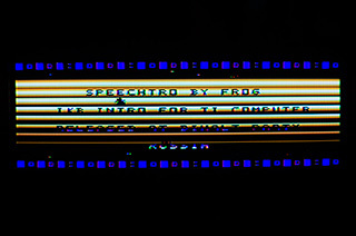
As for the image, I initially wanted to try to implement raster effects (changing the background color at the moment when the ray goes along the desired line). This turned out to be technically impossible (in the screenshots above you can see attempts to do this on a real TI and on emulators - MESS and js99er), so another option was chosen - to simulate raster effects through manipulation of attribute memory. In Graphics Mode 2, each 8x1 block can have an independent background color and image color, so each 1 pixel high bar can have different colors for the background and text. Despite the fact that there are only 15 colors (and only 10 are used in stripes), it seems that there are many more.
Separate difficulties caused the conclusion of the text. The design features of the TI-99 / 4a are such that the ROM (the so-called GROM) is not mapped to the address space of the processor, therefore, data for font output is extracted from GROM only sequentially (byte-by-bit) - by setting the starting address and reading the same memory location.
The selected “small caps” set has only the letters AZ (without numbers), which is easy to notice.
Stars, like a bug creeping obliquely, are implemented with 8x8 sprites.
In the process of pronouncing words in two rulers of squares, (conditionally) a part of the address of the current word is displayed in the ROM of the synthesizer.
Here you can see my works under different retro platforms, and here their sources on github.
Taking this opportunity, I also want to invite everyone interested in the Chaos Constructions festival , which we annually (from the last century) spend in St. Petersburg at the end of August, and where you can touch different retro computers live.
PS Thanks for the piece of iron, Kirill Timofeev and Timur Tashpulatov
Thus, TI99 / 4a (a slightly simpler TI-99/4 was released in 1979, and already TI-99 / 4a in 1981) inherited an extremely strange architecture for home computers. Firstly, the TMS9900 microprocessor in it is 16-bit - with an honest 16-bit data bus (this is in the late 1970s!). Secondly, there are no registers on the chip (except for PC, flags and the WP "register" pointer). What can be called registers is located in a separate 16-bit static RAM chip with a size of 256 bytes and can be addressed simultaneously as memory and (first 16 words) as R0..R15 registers. It's called a scratchpad.There is no hardware stack, instead, saving values when calling subprograms is done by changing the pointer to the beginning of the WP registers in this RAM itself (it resembles register windows in Sparc). In the ancestor (TI-990), it was also used to switch context when implementing multitasking.
Although the TMS9900 clock frequency is 3 MHz, the instructions take up quite a few clock cycles - at least 8. Even multiplication and division are implemented (124 clock cycles).
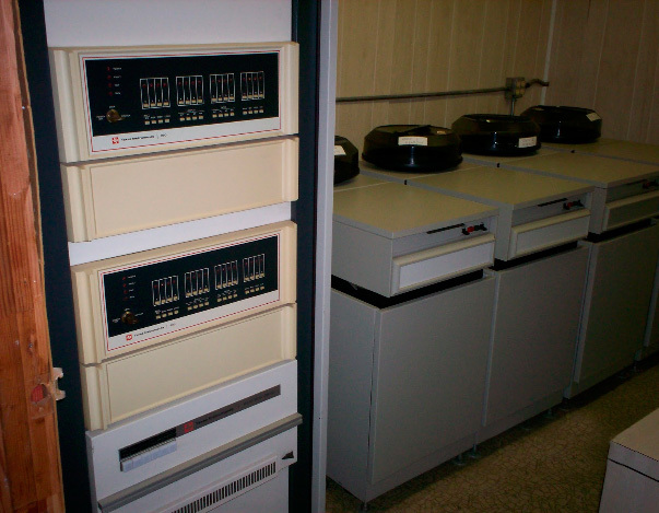 Everything except the processor, alas, is more ascetic. In addition to the tiny static RAM mentioned, there is also video memory - 16kb of slow 8-bit DRAM, which is accessed through a video controller.
In other words, without additional peripherals, the TI99 / 4A is a 16-bit computer with 256 bytes of RAM, built-in BASIC ROMs and cartridge programs (they have up to 8kb of honestly addressed ROMs or more, with different tricks).
It is impossible to load a normal program into a bare computer even from a cassette, because there is no RAM for this (256 bytes are not counted, and the rest is video memory).
Therefore, the minimum adequate computer configuration is PEB (Peripheral Expansion Box) - a special large basket for expansion cards, a drive and a 32kb memory extension. Or NanoPEB - a modern device that includes all of the above.
For PEB / NanoPEB, you also need an Editor / Assembler cartridge (without which you can only download and run programs on BASIC and which at the same time contains the mentioned additional 32kb of RAM).
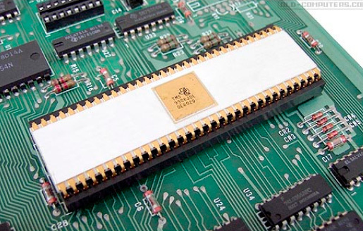 The TMS9918 video controller (also used in MSX and ColecoVision) supports graphic (256x192, 15 colors) and text modes, allows you to change the character generator, can display 32 hardware sprites 8x8 and 16x16 at the same time (true, no more than four pieces can be in one line at a time).
 Sound is output through TMS9919 (its analogue, SN76489, was used in IBM PCjr, BBC Micro, ColecoVision, some Sega consoles):
4 channels (three rectangle generators and one noise), 16 volume levels.
It is believed that such an uneven in terms of bit depth and sometimes awkward architecture was obtained due to the fact that the 8-bit version of the TMS9900 processor (TMS9985) was not ready at the time.
As for the software, the TI99 / 4A was intended for educational purposes (in fact, as opposed to Atari and Commodore). Together with the oddities of architecture described above, this has led to very few good games (if any). The fact that the computer was distributed exclusively in the USA added to this the absence of a demoscene (my 99tro intro was, it seems, the second on this platform).
CURRENT STATE OF BUSINESS
As already mentioned, little can be done with the bare TI99 / 4a, unless you can start something from the cartridges (if any). The PEB expansion basket required for normal operation is very expensive and takes up a lot of space. Since historically it turned out that all the serious development and, in general, any actions with TI were tied to the very PEB, modern fans of the machine went the way of emulating it (even nobody seems to bother with the emulator of ROM cartridges).
A modern substitute for PEB is NanoPEB . With some patience, it can be found on ebay or from individual sellers for 50 ... 80e.
This device sticks into the right port of the computer (the same place as the speech synthesizer. Including you can stick it through the synthesizer) and emulates 32kb of additional RAM, three drives (on a CompactFlash card) and an RS-232 port.
There is also a CF7 + device in which everything is the same, but instead of RS-232 there is a parallel Centronics port.
By itself, the presence of NanoPEB allows you to download only programs on BASIC (and from the standard TI BASIC it is impossible to run the program in machine codes, except for completely dirty and non-trivial hacks).
Therefore, the Editor / Assembler (EA) cartridge, stuck in the top port, is absolutely necessary. With it you can already download and run normal programs. The cartridge is also searched on ebay. It seems that you can use the cartridge Extended Basic (XB) instead.
To transfer programs to the CompactFlash card, you must use special utilities. The most popular is ti99dir (for Windows).
It is worth mentioning the F18A project - the implementation of the TMS9918A video controller on FPGA, with a number of additions. Those. the video chip in the usual TI-99 / 4a is replaced with a new one, while all the old software goes as before, but it is possible to display the image on a VGA monitor, set previously inaccessible video modes, etc.
DEVELOPMENT
In addition to Basic programs, which we will not talk about, there are two main formats in which a program can be represented in machine codes - for loading from a disk through Editor / Assembler and for a cartridge.
Files downloaded via EA are called EA3 (because in Editor / Assembler you need to select the third menu item - “LOAD AND RUN” to download them). They can be launched in any memory area (i.e., EA performs a link upon loading). For the emulator, such files are stored on a disk image (.DSK) and have a format of Dis / Fix 80.
Also, less often, memory image files called EA5 can come across (they are loaded into EA by selecting the fifth menu item - “RUN PROGRAM FILE”). These are already linked files tied to memory addresses. The emulator is also stored in disk images as "Program".
Downloading from a program disc in codes without fail requires the cartridge Editor / Assembler (or an analogue).
Programs for cartridges are rigidly tied to addresses and are just a binary that is flashed into ROM (for emulators, this is the .RPK format, less commonly - .BIN).
There are two substantially different approaches to writing assembly language programs. The first is the use of so-called GPL language. This is a cross between Extended Basic (XB) and Assembler, both in terms of performance and capabilities. Those. for all, the routines existing in the ROM are heavily used and, importantly, interrupts must be enabled.
The second option is assembler, which will be discussed.
The main unusual feature of the TI-99 / 4A is, in fact, in the TMS9900 processor. From the majority of processors that were used in home computers of that time, it is distinguished by the following:
Physically, the processor has only three registers - ST (flags), PC (command pointer) and WP (workspace pointer). Registers R0-R15 are located in the static RAM outside the chip. The address from which they start is stored in the WP register and can be changed. Usually it is set to> 8300 (the sign ">" means the hexadecimal system, the sign ":" - binary).
From> 8300 to> 83FF, there are 256 bytes of static 16-bit RAM called “scratchpad”.
Working with it is about 2 times faster than with the rest of the dynamic 8-bit (standard extension 32kb).
There are many addressing modes, and with one command you can, for example, transfer a value from a memory cell to another, changing it at the same time.
There is no stack in the processor - it is supposed to use the mapping of registers to any memory area with the LWPI addr command to save and restore the context.
The subprograms are called by the BL ADDR command , which puts the next address after it into the R11 register. Accordingly, B * R11 (aka RT) is used to return. There is also BLWP, which preserves workspace in addition to the return address (but at the same time slow).
Usually the first thing to do is turn off all interrupts and set the beginning of the registers to the beginning of the static RAM. Therefore, the procurement program looks like this:
       DEF  START
WRKSP  EQU  >8300
START  LIMI 0
       LWPI  WRKSP
...
* SOME CODE HERE
       END START
Because of this register architecture, programming features appear. Namely:
1. Registers can be accessed not only as R1, R2, etc., but (since they are in the address space) and as memory cells. This, in particular, allows you to work separately with the low and high bytes of the register, which for this are predefined by constants:
ws0       equ  >8300               ; Workspace 0
; Register direct low-byte access
R0L       equ  ws0+1               ; Workspace 0 R0 low byte
R1L       equ  ws0+3               ; Workspace 0 R1 low byte
R2L       equ  ws0+5               ; Workspace 0 R2 low byte
However, it is clear that it is far from always possible in a command to simply replace the register with memory (for this command, the desired addressing mode may simply not be available).
On the other hand, it is still necessary, because there are few commands working with halves of registers (MOVB, SWPB, AB, SB, some logic).
Of course, regardless of the currently installed workspace, there is always access to any register in any workspace (at the corresponding address in memory).
2. Since there is no stack (sometimes, however, it is simulated programmatically), saving and restoring registers is done by switching workspace. If you use this intensively, the available 256 bytes of fast SRAM will end quickly - they are always missing.
To show what the code for the TMS9900 looks like, a small example is Hello World:
        DEF     START
WRKSP   EQU     >8300
VDPWD   EQU     >8C00           * VDP RAM write data
VDPWA   EQU     >8C02           * VDP RAM read/write address
START   LIMI    0               * disable interrupts
        LWPI    WRKSP           * set default workspace
* set VDP RAM start address (low and high byte)
        LI      R0,>0000
        ORI     R0,>4000
        SWPB    R0
        MOVB    R0,@VDPWA
        SWPB    R0
        MOVB    R0,@VDPWA
        LI      R1,HELLOWORLD   * ascii string address
        LI      R2,12           * total chars
NEXTCHAR
        MOVB    *R1+,@VDPWD     * put next char on screen
        DEC     R2
        JNE     NEXTCHAR
LOOPBACK
        JMP LOOPBACK            * stop and do nothing
HELLOWORLD
        TEXT 'HELLO WORLD!'     * string data
        BYTE 0
        END START
This is a modern (not quite traditional) assembler TMS9900. Initially, in addition to the absence of colons after the marks, the registers were written not as R with a digit, but as a simple digit. Those. LI 4.5 and MOV 7.8 in the old assembler are LI R4.5 and MOV R7, R8 in the new.
It is easy to see that this did not add much to readability, so now they write R (although even modern assemblers understand the old version of the record). Some people, however, interfere with both syntaxes. As a result, in the same source code you can find a number of mnemonics SLA R5,0 (shift R5 to the left by the number of bits from the register R0) and SLA R5,1 (shift R5 to the left by _one_ bit).
Some (medical :) interest is in command X, which executes an instruction whose code is passed to it as a parameter.
; Здесь на самом деле выполняется инструкция B *R11
       LI   R9,>045B     ; код инструкции B *R11
       X    R9
; А здесь на самом деле выполняется инструкция LI R1,>1234
       LI   R0,>0201     ; код инструкции LI R1,xxx
       X    R0
       DATA >1234        ; это операнд xxx (>1234) для этой инструкции
It is believed that X can be used for debugging purposes, as well as for navigating tablets. Well, in any situations where you need a self-modifying code.
MEMORY CARD
> 0000 -----------
Console ROM
> 2000 -----------
Low memory expansion
> 4000 -----------
Peripheral cards ROM
> 6000 - ----------
Cartridge ROM / RAM
> 8000 -----------
Scratchpad RAM memory mapped devices
(C> 8300 to> 83FF contains 256 bytes of static RAM.
CPU registers are most often display starting from> 8300. From> 8400 to> 9C02 addresses for access to video, sound, synthesizer, GROM)
> A000 -----------
High memory expansion
(standard RAM extension 32kb. C> A000 usually a typical program loaded from disk begins)
...
> FFFF
As for ROMs, TI-99 / 4a uses the so-called GROMs. They are not mapped entirely to the address space of the processor, and data is accessed sequentially - the start address of the data is entered in GROM at a special address and then data is read from another special address from there. In this case, the current address of the GROM data increases automatically, with each reading.
Printing a string of characters from GROM
          li  r0, >0874           ; starting GROM address of small character set  GROMSC
          movb r0,@GROMWA          ; set GROM read pointer to address 06B0 (high part)
          nop                      ; wait a beat (not sure if necessary)
          movb @WR0LB,@GROMWA      ; set GROM read pointer to address 06B0 (low part)
          li   r0,>0000+(8*32*8)            ; VDP Pattern Table start address
          movb @R0L,@vdpwa         ; Send low byte of VDP RAM write address
          ori  r0,>4000            ; Set read/write bits 14 and 15 to write (01)
          movb r0,@vdpwa           ; Send high byte of VDP RAM write address
          li   r1,GROMRD
          li   r2,32
nextchar:
          movb *r1,@vdpwd
          movb *r1,@vdpwd
          movb *r1,@vdpwd
          movb *r1,@vdpwd
          movb *r1,@vdpwd
          movb *r1,@vdpwd
          movb *r1,@vdpwd
;          movb *r1,@vdpwd
          clr @vdpwd          ; skip one byte
          dec  r2
          jne  nextchar
GRAPHICS
To output graphics and text, the TDP-99 / 4a is equipped with the VDP TMS9918a video chip, which is also used in MSX1 and ColecoVision .
VDP allows you to display graphics with a resolution of 256x192 in 15 not very successful colors (+1 transparent, through which the background shines through) and monochrome sprites - 32 pieces of the same size 8x8 or 16x16 with a significant limitation: no more than 4 sprites on one line.
In VDP 16kb DRAM and it is distributed between graphics (text), colors and sprites.
Video memory does not map to the address space of the processor. To write to it, you must first enter the starting address in the video memory at which the address will be recorded at a specific address, and then write the necessary values in a row to another address (one). In this case, each subsequent value will appear in the video memory at the address increasing by one.
Depending on the video mode and memory allocation, you can choose the optimal mode in terms of addressing convenience, memory used and the number of colors (in the pixel block). At its core, all modes are text. In the sense that in all cases there is the concept of “characters” that can be placed in different places on the screen and which can be changed. But, since it is possible to reprogram the characters so that their appearance matches their code, in fact the mode is already "graphic". However, this is typical of many 1980s video controllers. Even in the relatively modern VGA there was such an opportunity (the author used it to implement the 640x400 fast mode with separate memory for colors).
Most often, TI uses Graphic Mode I (it is in this mode that the computer appears when it is turned on and initialized). In it, you can set two colors (background and image) per 8x8 block. Total blocks 32x24. The only advantage of this mode is the relatively high speed of color changes.
There is also a Multicolor mode - a graphic mode with a resolution of 64x48, where a color is set for each large pixel (but with this resolution, unless you draw some kind of plasma or ANSI art) and a couple of purely text modes 40x24 characters - color and monochrome.
The most powerful and interesting mode in VDP is the so-called Graphic Mode II (aka “bitmap mode”). This mode allows you to use two colors (background and image) inside an 8x1 pixel block. In other words, 2 colors for every 8 horizontal pixels. Unfortunately, the order of blocks (that of pixels, what of their colors) is extremely inconvenient for everything except character output - bytes go from top to bottom 0-8, then the next to the right again from top to bottom 8-15, etc. to the right edge. Then everything repeats again from left to right.
When setting the mode, addresses for the attributes (Color Table), bitmap (Pattern), the order of the characters that form the blocks for the bitmap (Name table), data for sprites (Sprites data) and attributes of sprites (Sprites Attributes) are also set. You can not set any addresses - there are just a few options that you should choose so that as a result, without overlapping, all 16384 bytes of video memory are rationally used. For example, for my intro “99tro” I allocated the memory like this (Graphics Mode II):
> 0000 -> 1800 Pattern table - 6144 bytes (> 1800)
> 1800 -> 2000 Sprite patterns - 64 sprites x 32 bytes = 2048 bytes (> 800)
> 2000 -> 3800 Color table - 6144 bytes (> 1800)
> 3800 -> 3b00 Name table - 768 bytes (> 300)
> 3b00 -> 3b80 Sprite attrs = 32 sprites x 4 bytes = 128 bytes (> 80)
Sprites can be of two sizes - 8x8 or 16x16 (all sprites switch at once) and you can additionally stretch them (also all at once) twice.
The total number of sprites is displayed simultaneously on screen 32 (but no more than 4 in one line). At the same time, 2kb of memory for Sprite patterns is enough for two sets of 32 16x16 sprites.
Individually for each sprite, you can set the following parameters (through the Sprite attrubutes area, for each byte in the series):
0 - vertical coordinate (-32 - 191)
1 - horizontal coordinate (0-255). 255 - sprite behind the right edge of the screen.
2 - pointer to the place where to get the pattern (in Sprites patterns)
3 - bits 4-7 determine the color, bit 0 - early clock (moves the sprite horizontally 32 pixels to the left)
The lack of direct addressing of video memory in combination with its unsuccessful organization and the absence of transfer instructions in the processor for more than a byte at a time does not allow it to be updated quickly. For example, the implementation of horizontal smooth scrolling of the 256x8 pixel region while playing VGM music in parallel almost completely takes the time of the beam backward movement in the frame. Those. there’s almost no more time left.
In games (modern), this problem is solved in rather cunning ways, when when scrolling, not the entire scrolling area is updated, but only requiring changes. Accordingly, the contents of the screen are thought out in such a way that there is a minimum of these changes. Graphics Mode I is also commonly used with a lower color resolution (two colors per 8x8 block).
As in many other systems, in TI-99 / 4a it is highly desirable to render the image fit into the vertical retrace of the beam. To do this, VDP generates an appropriate interrupt - at the beginning of drawing the bottom of the frame.
 There are the following options:
 1. Interrupts can be disabled completely (LIMI 0 + instruction specifically for VDP - setting the corresponding bit in register 1). In this case, everything will be faster, but it will not work to track the reverse beam in any way.
2. Switch on interruptions completely (LIMI 2 and in VDP). Then you can hang your own interrupt handler that will do something.
3. Enable interrupts in VDP, but disable them with the LIMI 0 instruction. In this case, no handlers will be called, but you can manually monitor the beam backward by checking the bit in the VDP status register (after reading the register, this bit is automatically reset. If it is not reset, then the next interrupt will not be generated).
vwait:
          movb >8802,r12 ; read VDP status register
          andi r12,>8000
          jeq  vwait                ; Wait for vsync
A fairly typical scheme is when interrupts from VDP are turned on, general ones are turned off (LIMI 0), but in the main loop they are turned on (LIMI 2) for a short period of time, so that a processor that hangs on an interrupt (for example, playing music) sometimes gets control.
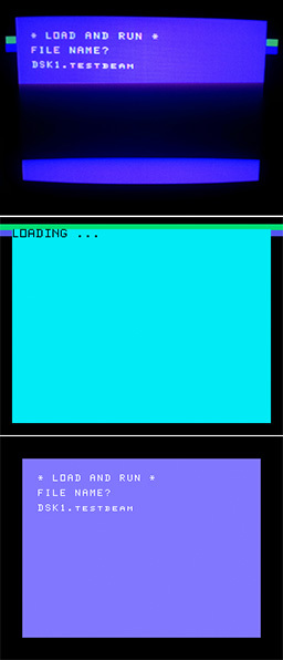
Not all emulators correctly mimic this interrupt. But, say, MESS does this more or less adequately. In the picture you can see a simple test - the color of the frame changes with some delay relative to the vertical retrace (on the real TI and on two emulators - MESS and js99er).
SOUND
1. Standard sound
For receiving music and sound effects, a TMS9919 chip is installed in the TI-99 / 4a (analogs: SN76489, SN76496). It is quite simple: three independent tone generators and one noise generator. 15 volume levels.
Since this is a fairly popular chip (used in some consoles, in IBM PCjr / Tandy-1000, etc.), there is a lot of information on it.
For TI-99 / 4a, there is a MOD2PSG tracker (it normally starts under Win7 64bit). In particular, it allows you to download psgmod files and export vgm and epsgmod.
There are two working players - EPSGMOD Player by Tursi (requires data in epsgmod format, hangs its handler to interrupt VDP).
It is connected as follows:
        def  start
start:
        lwpi >8320
        li  r0,musicdata
        bl  @SGPLAY
again:
        limi    2
        limi    0
; .... your code (vsync etc..) ...
        b    @again
musicdata:
        bcopy   "music.epsgmod"
        copy    "test_music_playervbr.a99"
        copy    "test_music_player.a99"
        end    start
With this connection of the player, it is necessary to remove REF and END from its sources (since they are oriented to use with traditional assembler).
Note that in the main loop, interrupts are activated for a moment (limi 2). This is necessary for the player to work, which works by interrupting the VDP from the reverse beam (occurring every 1/60 second). In this case, the SGTICK subroutine of the player is called.
Accordingly, it is important that for NTSC the computer version and the music must also be NTSC (the frame rate must match).
The second player (of the same author) plays VGM format files (also includes the VGMComp utility for VGM compression). This handler does not hang up, you need to call it manually with a frequency of 60Hz.
It looks like this:
          def  start
vdpsta    equ  >8802               ; VDP RAM status
start:
          limi 0
          lwpi ws0               ; player expects our workspace to be >8300
          clr  r2
          li   r1,musicdata
          bl   @stinit
again:
          clr  r12                 ; set CRU base (doesn't need to be in loop, but provides delay)
          tb   2                   ; check VDP interrupt input (Tests a CRU bit)
          jeq  loop                ; if not set, skip calling music
          movb @vdpsta,r12         ; read status register, which in turn clears the interrupt bit
          bl   @stplay             ; call play function - it returns with the wrong workspace
* check for song end
          movb @songwp+14,r3
          jne  notdone
          clr  r2                   ; play again
          li   r1,musicdata
          bl   @stinit
notdone:
          lwpi >8300               ; so restore the right one
; .... your code (vsync etc..) ...
          b    @again
musicdata:
          bcopy  "music.vgm"
          copy   "tiplayer.a99"
          end    start
In my opinion, the second version of the player has better quality (although it may depend on specific music) and manual call is more flexible than a handler (which you yourself can hang, if you really need to) - you do not need to enable interrupts.
He also has a 30Hz player option. At the same time, it must also be called at a frequency of 60 Hz, but it will be used every second call. Accordingly, the processor load is reduced, but the sound quality of the music can potentially drop (depending on the effects used in it).
Apparently, there is a bug in the player (or when exporting to VGM) that creates incomprehensible problems with looping music.
2. Speech synthesizer
Since the speech synthesizer is a very popular peripheral for the TI-99 / 4a, quite a few programs use it. The synthesizer attaches to the port on the right side of the computer (if you have NanoPEB, you can plug it directly into the synthesizer). Inside is a ROM with data for words, an LPC decoder (TMS5220), and a DAC. There are two operating modes. In the first, the computer tells the synthesizer which words from the ROM should be pronounced (there are few words there). In the second (Speak-External), it is possible to transfer directly compressed LPC data, which the synthesizer will simply reproduce. For data packaging, the ancient QBox Pro program is used, which runs under WinXP (the process is shown here ).
The synthesizer can be controlled directly from the assembler program. If you just want to play around, then you need a cartridge - for example, Speech Editor (allows you to pronounce the typed text, and also adds commands to play words in the standard Basic). The Terminal Emulator cartridge allows you to pronounce individual phonemes and combine them into arbitrary words.
In the most famous emulators, the synthesizer is supported. It is believed that the best support (the hardware is fully emulated) is implemented in MESS / MAME.
Below is an example that pronounces the word "HELLO" taking LPC data from the ROM of the synthesizer. The documentation indicates that status checking is not possible if the code is running in RAM on an 8 bit bus (i.e. it is required that the code is on a 16 bit scratchpad), however, after checking on emulators and a real computer, I consider this to be reinsurance (probably like and in the case of VDP, all these requirements relate to some very early versions of iron). The result is such a short code:
; speaks 'HELLO' from speech synth ROM
    def  start
SPCHRD  equ  >9000       ; addr to read from synth
SPCHWT  equ  >9400       ; addr to write to synth   (>10 - read, >4x - Load-Address, >50 - speak, >60 = speak-ext )
H50   BYTE  >50      ; speak command
start:
    limi  0
; loading speech address (5 nibbles of data required) using >4x Load-Address command
; >4x >4x >4x >4x >40 (end marker >0)
    li    r0,>351a ; address of 'HELLO' in synth ROM
    li    r2,4    ; 4 nibbles
loadlp:
    src   r0,4    ; start with least significant nibble
    mov   r0,r1
    src   r1,4
    andi  r1,>0f00 ; get only particular nibble
    ori   r1,>4000 ; put in >4x00 format
    movb  r1,@SPCHWT  ; write nibble
    dec   r2
    jne   loadlp
    li    r1,>4000
    movb  r1,@SPCHWT  ; write fifth nibble (end marker)
    movb  @H50,@SPCHWT  ; execute speak command
loopback:
    b     @loopback
    end   start
The addresses of all the words from the ROM can be found in the book Editor Assembler Manual.
If you want to play arbitrary speech converted to LPC using QBox Pro, then in the simplest case, the code will look like this:
  def  SPEAK
SPEAK
  li   r2,1750    ; number of speech BYTEs to poke (see end of QBox data)
  li   r3,speech  ; speech data address
  limi 0      ; no interrupts
loop
  movb *r3+,@>9400 ; poke a  BYTE of speech data
  dec  r2
  jeq  quit     ; repeat until end of data
  jmp  loop ; else go 'round again
quit
  limi 2 ; interrupts allowed
  rt
speech
; 10 Voiced 4 Unvoiced 8 kHz 5220
; [Coded LPC]
; .... данные из *.sfm полученном при помощи QBox Pro
; nb bytes: [1750]
 end
For QBox Pro you need to prepare a wav file with a speech. A clear male speech will sound best. One phrase will occupy about a kilobyte.
Passing singing or sheet music will not work. After coding in LPC, such sounds will be completely unrecognizable.
Settings and operations in QBox Pro:
byte
8khz
5220
Project/Add files
select file
Process/Medium bit rate /OK
Edit/Concatenations
Insert/Concatenation/Concat Name/ "TEST"
Insert/Phrase/OK
Format/LPC 10V, 4UV      /OK
Project/Exit/Save
Result: test.sfm
CROSS-MEANS
To develop and test programs on a PC, and then download them to TI-99 / 4a, you need the following:
Hardware:
- PC / Win7 (64bit is suitable)
- TI-99 / 4a
- Cartridge Editor / Assembler (or any other that allows you to download and run programs in machine codes)
- NanoPEB or CF7 + (for emulating a drive and loading a program from a CompactFlash card into TI-99 / 4a)
Software:
- One of the many TI-99 / 4a emulators is MESS / MAME or js99er (or better, several )
- The xdt99 package, which includes assembler and utilities for working with files and disk images (in particular, xvm99 for writing a disk image to a CompactFlash card, in the format needed for NanoPEB)
Organization of the process:
Programs for a cartridge and for loading from a disk are two different things. Not only in format (RPK and DSK), but also in terms of working with memory (the second option pauses the 32kb memory extension). If there is a goal in the end to run the code on a real machine, you need to focus on the disk version. We will consider it.
Emulators are significantly different from each other, it is very difficult to name the best. This is not only a question of the quality of emulation, but also the convenience / simplicity of launching a finished program.
The most famous: mess (mame), js99er, v9t9, classic99.
All of them are not perfect. It is quite possible to expect a 10% difference in speed between the emulator and the real piece of hardware (specifically, I observed that mess and js99er execute all the code a little faster than the real TI. In the same NTSC)
When using xdt99 as an assembler, the process looks like this:
xas99.py -R --jumpstart %1.a99 (получаем объектный файл)The -R option allows you to properly name registers in the source text (r0, r1, ...). In the traditional TMS9900 assembler, registers in commands are written simply in numbers, which introduces wild confusion.
xdm99.py work.dsk -a %1.obj -n %1-O -f DIS/FIX80 (помещаем полученный объектный файл на образ диска)Keep in mind that the object file is a text file with hexadecimal codes inside. Although this is not a final binary file, nevertheless, due to the peculiarities of downloading programs on TI-99 / 4a (via Editor / Assembler), it is often considered a ready-made program. All the more convenient because it is usually not tied to a specific area of memory at boot time.
If the final binary is required, add the -i option for xas99. Then it will be necessary to load it not through point 3, but through point 5 in the Editor / Assembler. If you need a final binary file of more than 8k, without splitting into separate parts, instead of -i you need to use -b.
Additionally, you can get the .lst listing file by specifying the -L option.
A special cartridge image for automatic loading simplifies the work somewhat (see "jumpstarting" in the xdt99 documentation). The image allows you to do without the Editor / Assembler in the emulator, pressing buttons in it and entering the file name. The finished code is loaded from the disk automatically when you select a cartridge. For example, mess (mame) in this case starts like this:
mame64.exe ti99_4a -peb:slot8 tifdc -peb:slot2 speech -flop1 %1.dsk -cart jumpstart.rpk -window -ui_active -skip_gameinfoIf you need a debugger, you can also add -debug (entering the debugger from the emulator, provided that the option was specified - with the `key)
The parameter" ti99_4a "replaces the NTSC version of the computer (ie the most common). For the PAL version, this will be ti99_4ae.
The difference is very significant, at least because of the different frame rates. in the first case, personnel 60Hz, in the second 50Hz. Wrong choices can lead, for example, to slow-down music playback (if it was written under NTSC and PAL is selected).
If the application you are developing is significant in size or if something takes noticeable time, you can speed up the emulation with the -speed 20 option.
You can use xvm99.py to transfer a program record to CompactFlash in NanoPEB format
\\.\PHYSICALDRIVE2 1 -w work.dskMake sure that on your computer PHYSICALDRIVE2 corresponds to the device in which the CF is inserted (otherwise you can spoil the data on your disks!). On Windows, this can be viewed with the command
wmic diskdrive list brief /format:listSince there can be several images on one CF to emulate several drives, the second parameter corresponds to the drive - i.e. DSK1 for 1).
Preliminary it is recommended to format CF under FAT16, after which it is mandatory to type “call format (1)” on TI itself with NanoPEB inserted from TI Basic, where 1 is the number of the formatted virtual drive.
View flash drive content:
xvm99.py \\.\PHYSICALDRIVE2 1 -iWhen loading a program on TI itself, you need to insert a cartridge with Editor / Assembler and NanoPEB. Turn on NanoPEB, then the computer. In the menu, select option "2" - "Editor / Assembler", in it item 3 (or 5), type DSK1.FILENAME and press ENTER.
Case in the file name is important.
APPENDIX 1 - Intro 99TRO
In the process of studying TI-99 / 4a, I wrote “99tro” (source) - a small invitation intro at Chaos Constructions'2016, presented at Revision'2016. In addition to its source code (the code is very terrible - do not write it like that!) Some explanations will be given here.
The main idea is for the intro to convey the style of the old cracktro for the Commodore 64, if possible, naturally adjusted for the more modest capabilities of the TI-99 / 4a video and audio chips. Roughly speaking, I wanted something like a color logo, a smoothly scrolling text line, iridescent colored stripes and a dangling inscription from sprites.
 Soon, the following significant limitations and shortcomings of the computer became clear:
- There is no hardware scrolling, it can only be done by shifting and rewriting video memory
- Exchange with video memory (this also applies to sprites and graphics and text) is very slow and the relatively high processor frequency does not save (as well as its 16-bit, because exchange with VDP goes on the 8-bit bus).
- VDP has a number of undocumented or inaudibly documented bugs (which is not surprising, TMS9918 is one of the first specialized video chips). A couple of times this led to the fact that the already almost finished part had to be abandoned.
- Very limited functionality of sprites - only 4 per line (which automatically means that you can’t do anything wide with sprites on the screen), monochrome, a large number of processor instructions for a simple change of color or coordinate of the sprite.
- Playing music (vgm) takes a very substantial processor time. As stated in the source code of the player from Tursi, this is 2-20% for the 30Hz version, depending on the specific music. In my particular case, at least 10-15% was obtained.
- The trouble is with convenient debuggers (in fact, the same picture was with the Vectrex emulator - in both cases there are powerful debuggers, but inconvenient so that, in fact, their use is more likely to slow down than to speed up)
- Inability to quickly check the code for real iron. To do this, turn everything off, remove the USB flash drive, insert it into the PC, copy the code onto it, remove it from the PC and paste it into TI, turn on the disk emulator and TI itself, select Editor / Assembler, select the program load point, type DSK1.program_name, press ENTER Wait for download (about a minute).
As a result, gradually, only what was allowed to implement the piece of iron was left from the previous ideas (of course, taking into account that this was my first program for this platform and this processor):
- CHAOS CONSTRUCTIONS'2016 inscription / logo with the robot head
- Flashing to the beat of music eyes and mouth of the robot
- Appearing letter by letter, following the pulsating cursor, text in several lines
- Smoothly scrolling text line
- Background music (vgm)
In order to somehow use the strengths of TI-99 / 4a, I chose the mode with the maximum graphic and color resolution - Graphics mode II (Bitmap). For games it is used extremely rarely, because it requires all 16kb of video memory and, accordingly, is very slow in terms of updating the image.
However, unlike games, in my case it was possible to go for a trick (which is generally characteristic of demo and intro) - I did not dynamically update the colors at all anywhere else. Everything related to flowers was established only once at the beginning, outside the main cycle.
In the cycle, only bitmap changed and two sprites switched.
The upper logo was first drawn in Photoshop, then converted to a video memory dump for VDP using the Convert9918 utility, and then these two steps were cyclically repeated - i.e. Refinements were made to the original image so that after conversion (in 15 rather curved colors and color resolution 2 colors by 8 horizontal pixels) it would look as adequate as possible. I must say that the distortions characteristic of the composite NTSC signal played, as often happens in such cases, on the hand - on the CRT monitor the picture looks clearly better than in the emulator (besides, it is warmer and lighter). I must say, for the first time I seriously realized how important the correct choice of 16 possible colors of its (platform) developers is for the success of the platform. In the case of TI-99 / 4a, these colors are extremely unsuccessful (in addition, there are 15 of them).
In addition, for the first time I had to deal with the problem of color coding in an NTSC video signal. The photo shows what the colors for single pixels turn into (in PAL, this also causes problems, but incomparably smaller).
The bottom smooth scrolling was taken from a single similar example (Matthew Hagerty) and modified. Honestly. for such a short time I could hardly penetrate the TMS9900 assembler deep enough to repeat some of the techniques used there, without which there would simply not be enough overall performance for all the work.
In scrolling, the parts of the characters are cunningly shifted to the left and the result is copied to VRAM. In total, an area of 8 pixels in height will scroll.
As I said above, operations are performed exclusively on a bitmap - a colored background in the form of a white and blue strip is drawn in advance and is not affected by scrolling.
Since scrolling is the most expensive operation in the main cycle, everything further pushed away from it and from the music (if you stop fitting into the backward beam, the music will begin to slow down).
Unfortunately, in fact, it still slows down a little because both emulators on which I debugged the code worked a little faster than the real piece of iron. What exactly is the problem is unclear.
The text behind the cursor is written in the middle of the screen. I had a lot of ideas how to implement this beautifully, but in the end I had to abandon everyone because of the slow video memory and VDP bugs. As a result, one letter is drawn for each iteration of the loop (i.e., 8 bytes of video memory are updated). For all eight possible lines of text, a background is set in advance with a smooth transition between shades of blue and gray.
The pulsating cursor is a sprite for which the image is taken cyclically from four memory locations - i.e. it turns out four frames of a square of different sizes.
As for the blinking eyes and mouth of the robot, they are implemented in three frames of one 16x16 sprite (again, with the goal of gaining in performance). A particular frame is selected depending on the volume of one of the channels of the sound chip (this data is returned by the player).
Sprites and fonts were edited in the Magellan program.
The code uses three different workspace for processor registers - one for the player (and it requires not only a workspace, but also a piece of scratchpad - valuable 16-bit RAM, because of which it was not possible to increase the speed of code execution by moving its parts there), the second for scrolling and the third for everything else (counters in a loop, cursor coordinates, etc.)
As a result, the total intro size was around 22kb. The main part, of course, is uncompressed graphics (12kb) and RLE compressed music (1.8kb). Thus, the code itself takes somewhere in the region of 6-7kb (and even then there are fragments that were used only for debugging).
APPENDIX 2 - Intro Speechtro
A one-kilobyte intro called “Speechtro” (source) was written shortly after 99tro and was presented at DIHALT'2016 (where it won first place in the 1kb low end intro).
At the core were two ideas:
1. To do something using a speech synthesizer (among the owners of TI-99 / 4a it is very common, and also well supported by emulators - MESS / MAME and js99er).
2. Try to visualize a large number of colors with imitation of raster effects.
After some hesitation, it was decided to combine both ideas into one work.Speech uses the words flashed into the synthesizer ROM (since in the case of direct LPC compression of 1 kb, so much speech would not fit). Since there are very few of them in ROM, it took quite a while to compose a coherent speech on a suitable topic from the available words. Unfortunately, pauses in the synthesizer dictionary are not provided. As a pause, I used a rather random address, the data from which sounds like “gurgling”. This, firstly, saves and simplifies the code, and secondly, it sounds more interesting than just silence.
As for the image, I initially wanted to try to implement raster effects (changing the background color at the moment when the ray goes along the desired line). This turned out to be technically impossible (in the screenshots above you can see attempts to do this on a real TI and on emulators - MESS and js99er), so another option was chosen - to simulate raster effects through manipulation of attribute memory. In Graphics Mode 2, each 8x1 block can have an independent background color and image color, so each 1 pixel high bar can have different colors for the background and text. Despite the fact that there are only 15 colors (and only 10 are used in stripes), it seems that there are many more.
Separate difficulties caused the conclusion of the text. The design features of the TI-99 / 4a are such that the ROM (the so-called GROM) is not mapped to the address space of the processor, therefore, data for font output is extracted from GROM only sequentially (byte-by-bit) - by setting the starting address and reading the same memory location.
The selected “small caps” set has only the letters AZ (without numbers), which is easy to notice.
Stars, like a bug creeping obliquely, are implemented with 8x8 sprites.
In the process of pronouncing words in two rulers of squares, (conditionally) a part of the address of the current word is displayed in the ROM of the synthesizer.
RESOURCE LINKS FOR TI-99 / 4a
- My seminar at CC'2016: "Computer 'Texas Instruments TI-99 / 4a' 1980 and development for it"
- The main resource for iron TI-99 / 4a
- Core Development Forum for TI-99 / 4a
- Various software, magazines, etc.
- The best cross-assembler and utilities for it
- NanoPEB (CF7 +)
- Cartridge Emulator (NanoPEB Alternative)
- Useful documentation and books, in one archive
- Running small programs in codes inside scratchpad (without Editor / Assembler and without memory expansion)
- Good js emulator
- Work with the cassette player
- Useful software
- Game Development Library
Here you can see my works under different retro platforms, and here their sources on github.
Taking this opportunity, I also want to invite everyone interested in the Chaos Constructions festival , which we annually (from the last century) spend in St. Petersburg at the end of August, and where you can touch different retro computers live.
PS Thanks for the piece of iron, Kirill Timofeev and Timur Tashpulatov









