VHDL state machine implementation
Finite state machines play a very important role in the development of FPGA firmware. Everyone has heard of two classic types of machines: the Miles machine and the Moore machine, which were proposed even before the FPGA. However, the specifics of constructing FPGAs makes its own adjustments and in the process of work I have developed a very definite style of describing an automaton.
The literature offers various implementations of automata. Such article is also on Habr - "Description of digital automatic machines on VHDL" from canny . However, in practical implementation on FPGAs, especially at high frequencies, such an implementation is inconvenient. The following option is proposed.
Component Description:
Description of type and signals:
Reset Sync:
The machine itself, in this case is very simple
Features:
There is nothing revolutionary here, all this has long been known. But all together this just forms the description style.
In more detail about features of the description. This is primarily the introduction of a separate type for the status signal. In this case, the enumeration type is described. This allows the synthesizer to select the type of signal. It can be one-hot, it can be a binary counter or a Gray counter. The type of implementation may be specified by synthesizer directives. This separates the description from the implementation. If someone does not like this, then it is quite possible to set the type std_logic_vector and the individual constants s0, s1, etc. Sometimes they make complaints to me that the names s0, s1 are not informative, and it would be better to use constants related in meaning to a specific state. So I also tried to do it, but in the development process very often the logic of the state changes but the name remains, and this only confuses the matter.
Synchronization of the reset signal - very often, reset is asynchronous with respect to the clock frequency of the machine. In order not to check where it comes from, it is better to always put two triggers. In any case, this will facilitate tracing. Reset only affects the status signal. It also facilitates tracing, especially with a large number of output signals, but this requires that in the initial state all output signals are described.
The machine is a synchronous circuit, therefore, all input signals must be synchronous with a clock frequency, there are no options here. It is necessary to know where the signal comes from. If this signal is generated at a different clock frequency, then it is mandatory to put two triggers (as well as for the reset signal).
The fact that the transitions and output signals are described in one process visually simplifies the development process and increases visibility. If you make an automaton in two (or even in three processes) as the textbooks advise us, it’s hard to catch a glance. If only because a large machine on one computer screen does not fit.
The most controversial statement is the record after 1 ns when assigning a signal. At one of the forums I was criticized very strongly for this. They also wrote that as experience accumulates, I will get rid of this bad habit. My experience shows that this is a very good habit. The presence of such a record allows us to be sure that the simulation results and the results of work in real equipment will be the same. It's all about the concept of delta delays.
Consider a simple language construct:
The result of the work is presented in the figure:
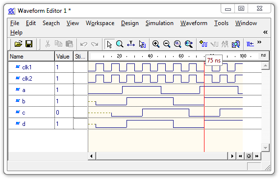
The diagram visually shows that the clock signals clk1 and clk2 coincide, but in fact clk2 is delayed relative to clk1 by the value of the delta delay. Signal c is behind the signal b by one clock cycle. It is right. But the signal d must coincide with the signal c , but this does not happen. It works earlier. This is due to the fact that it snaps into clk2 frequency . When working in hardware, clk2 will completely match clk1, it will be the same signal on the global clock line. In real projects, assignments like clk2 <= clk1 are common enough. Of course, you can try all developers to strictly forbid doing this, but I strongly doubt the result. Instead of assignment, you can make a description of the alias type:
In this case, clk2 will be just another clk1 name and the results will be correct. But there is one more point. Purely visually, it is not clear on the time diagram when the signal changes relative to the clock frequency.
And here's what happens when you add after 1 ns:

Signals c and d are formed correctly. The change in signal b is clearly visible relative to the front of the clock frequency.
Once, many years ago, I spent a lot of time searching for the causes of various behaviors in the model and in real equipment. The shift was only one beat. And this is precisely the reason - the assignment of the clock frequency and the absence of after 1 ns. Since then I always add a delay and have never regretted it.
And finally, the example shows the Moore automaton. The output signals depend only on the state. But the code can always be changed, for example like this:
In this case, the signal q will be generated one cycle earlier, i.e. it will depend on the status and input signal. And this is already a Miles machine.
The article Description of Digital Automata on VHDL will also provide a description in one process. At first glance, everything coincides.
There is a very serious mistake in this description. During the action of the reset signal, the OUTPUT output signal is not defined; to determine it, you need to enter the signal purpose inside the reset:
In this case, three reset lines are added. With a large number of output signals, this worsens the FPGA trace.
In my case, the reset signal acts only on the status signal, but since it is inside the process after the case, in accordance with the rules of the language, it takes precedence over the purpose of the state inside the case. The peculiarity of this solution is that the transfer of the output signals to the initial state will occur only on the second cycle of the reset signal. However, in the vast majority of cases this is not significant.
In conclusion, I want to note that this style of description is very well established, the machine is well bred in FPGA. Cascade connections of several machines and connections to other circuits inside the FPGA are easily obtained.
The literature offers various implementations of automata. Such article is also on Habr - "Description of digital automatic machines on VHDL" from canny . However, in practical implementation on FPGAs, especially at high frequencies, such an implementation is inconvenient. The following option is proposed.
Component Description:
entity  ex_user is
port (
   reset  : in std_logic: -- 1 – сброс
   clk      : in std_logic; -- тактовая частота
   a        : in std_logic;   -- вход автомата
   q        : out std_logic  -- выход автомата
)
end ex_user;
Description of type and signals:
type  stp_type is ( s0, s1, s2, s3 );
signal stp          : stp_type;
signal rstp0       : std_logic;
signal rstp         : std_logic;
Reset Sync:
rstp0 <= reset after 1 ns when rising_edge( clk );
 rstp <= rstp0 after 1 ns when rising_edge( clk );
The machine itself, in this case is very simple
pr_stp: process( clk ) begin
 if( rising_edge( clk ) ) then
  case( stp ) is
    when s0 => -- это начальное значение
          q <= ‘0’ after 1 ns;
	  if( a=’1’ ) then
                 stp <= s1 after 1 ns;
          end if;
   when s1 => -- что то делаем, например ждём a=0
        if( a=’0’ ) then
               stp <= s2 after 1 ns;
	end if;
   when s2 =>
	q <= ‘1’ after 1 ns;
	stp <= s0 after 1 ns;
   end case;
   --- А вот это сброс, он действует только на stp ---
   if( rstp=’1’ ) then
     stp <= s0 after 1 ns; -- действие только на stp
   end if;
 end if;
end process;
Features:
- Description of the individual type for status signal
- Signal Reset
- Reset only affects status signal
- All input signals must be synchronous with the clock frequency of the machine
- Transitions and outputs are described in one process.
- Availability after 1 ns - to facilitate modeling
- Both a Moore machine and a Mile machine can be implemented
There is nothing revolutionary here, all this has long been known. But all together this just forms the description style.
In more detail about features of the description. This is primarily the introduction of a separate type for the status signal. In this case, the enumeration type is described. This allows the synthesizer to select the type of signal. It can be one-hot, it can be a binary counter or a Gray counter. The type of implementation may be specified by synthesizer directives. This separates the description from the implementation. If someone does not like this, then it is quite possible to set the type std_logic_vector and the individual constants s0, s1, etc. Sometimes they make complaints to me that the names s0, s1 are not informative, and it would be better to use constants related in meaning to a specific state. So I also tried to do it, but in the development process very often the logic of the state changes but the name remains, and this only confuses the matter.
Synchronization of the reset signal - very often, reset is asynchronous with respect to the clock frequency of the machine. In order not to check where it comes from, it is better to always put two triggers. In any case, this will facilitate tracing. Reset only affects the status signal. It also facilitates tracing, especially with a large number of output signals, but this requires that in the initial state all output signals are described.
The machine is a synchronous circuit, therefore, all input signals must be synchronous with a clock frequency, there are no options here. It is necessary to know where the signal comes from. If this signal is generated at a different clock frequency, then it is mandatory to put two triggers (as well as for the reset signal).
The fact that the transitions and output signals are described in one process visually simplifies the development process and increases visibility. If you make an automaton in two (or even in three processes) as the textbooks advise us, it’s hard to catch a glance. If only because a large machine on one computer screen does not fit.
The most controversial statement is the record after 1 ns when assigning a signal. At one of the forums I was criticized very strongly for this. They also wrote that as experience accumulates, I will get rid of this bad habit. My experience shows that this is a very good habit. The presence of such a record allows us to be sure that the simulation results and the results of work in real equipment will be the same. It's all about the concept of delta delays.
Consider a simple language construct:
clk2 <= clk1;
b <= a when rising_edge( clk1 );
c <= b when rising_edge( clk1 );
d <= b when rising_edge( clk2 );
The result of the work is presented in the figure:
The diagram visually shows that the clock signals clk1 and clk2 coincide, but in fact clk2 is delayed relative to clk1 by the value of the delta delay. Signal c is behind the signal b by one clock cycle. It is right. But the signal d must coincide with the signal c , but this does not happen. It works earlier. This is due to the fact that it snaps into clk2 frequency . When working in hardware, clk2 will completely match clk1, it will be the same signal on the global clock line. In real projects, assignments like clk2 <= clk1 are common enough. Of course, you can try all developers to strictly forbid doing this, but I strongly doubt the result. Instead of assignment, you can make a description of the alias type:
alias clk2 is clk1;In this case, clk2 will be just another clk1 name and the results will be correct. But there is one more point. Purely visually, it is not clear on the time diagram when the signal changes relative to the clock frequency.
And here's what happens when you add after 1 ns:
Signals c and d are formed correctly. The change in signal b is clearly visible relative to the front of the clock frequency.
Once, many years ago, I spent a lot of time searching for the causes of various behaviors in the model and in real equipment. The shift was only one beat. And this is precisely the reason - the assignment of the clock frequency and the absence of after 1 ns. Since then I always add a delay and have never regretted it.
And finally, the example shows the Moore automaton. The output signals depend only on the state. But the code can always be changed, for example like this:
  when s1 => -- что то делаем, например ждём a=0
           if( a=’0’ ) then
               stp <= s2 after 1 ns;
               q <= ‘1’ after 1 ns;
	end if;
In this case, the signal q will be generated one cycle earlier, i.e. it will depend on the status and input signal. And this is already a Miles machine.
The article Description of Digital Automata on VHDL will also provide a description in one process. At first glance, everything coincides.
Description of CA in one process
PROCESS (clk, reset)
BEGIN
	IF reset = '1'
		THEN state <= Init;
	ELSIF (rising_edge(clk)) THEN
		CASE state IS
			WHEN Init =>
				IF cnt = '1'
					THEN state <= R;
				ELSE
					state <= Init;
				END IF;
				output <= "000";
			WHEN R =>
				IF cnt = '1'
					THEN state <= RG;
				ELSE
					state <= R;
				END IF;
				output <= "100";
			WHEN RG =>
				IF cnt = '1'
					THEN state <= G;
				ELSE
					state <= RG;
				END IF;
				output <= "010";
			WHEN G =>
				IF cnt = '1'
					THEN state <= GR;
				ELSE
					state <= G;
				END IF;
				output <= "001";
			WHEN GR =>
				IF cnt = '1'
					THEN state <= R;
				ELSE
					state <= GR;
				END IF;
				OUTPUT <= "010";
		END CASE;
	END IF;
END PROCESS;
There is a very serious mistake in this description. During the action of the reset signal, the OUTPUT output signal is not defined; to determine it, you need to enter the signal purpose inside the reset:
	IF reset = '1'
		THEN state <= Init;
                OUTPUT <= "000";
       ELSIF
In this case, three reset lines are added. With a large number of output signals, this worsens the FPGA trace.
In my case, the reset signal acts only on the status signal, but since it is inside the process after the case, in accordance with the rules of the language, it takes precedence over the purpose of the state inside the case. The peculiarity of this solution is that the transfer of the output signals to the initial state will occur only on the second cycle of the reset signal. However, in the vast majority of cases this is not significant.
In conclusion, I want to note that this style of description is very well established, the machine is well bred in FPGA. Cascade connections of several machines and connections to other circuits inside the FPGA are easily obtained.