Responsible Relative Humidity Measurement
With this article, we continue to talk about sensors from the Swiss company IST. Not so long ago, posts were published on sensors of electrical conductivity of water and sensors for the flow rate of liquids and gases , today the turn has come to relative humidity.

The article is devoted to high-precision sensors of the HYT series. The description of the sensor device and the sensor element is given, the order of pairing the sensor with the microcontroller is described in detail, an example of development is given.
Standard HYT models are three sensors for measuring temperature and relative humidity, built on the basis of the same sensing element, but made in different cases.
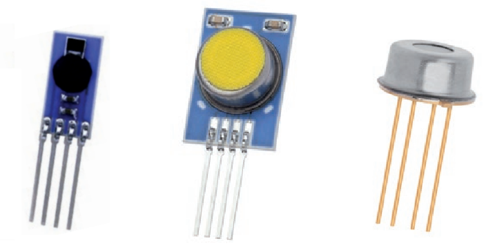
We will talk about other packaging options below, but for now, we’ll give the main characteristics of the HYT sensors.
It is clear that such high accuracy and stability will not be useful in the home weather station tm . HYT sensors are used in industry - in household appliances, in processes that are related to drying, evaporation and distillation, in analyzers of residual moisture of various materials, in medical equipment, in ventilation systems and in other “critical applications”.
 Like most modern RH sensors, HYT sensors have a capacitive sensor. The principles of operation of the humidity-capacity converters and their advantages are described in a huge number of sources, let me remind you the main thing.
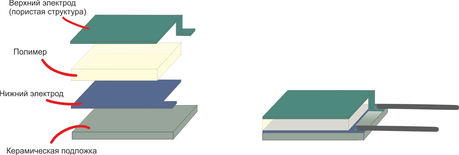
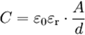
The capacitive sensor is a ceramic substrate on which the lower conductive electrode, the moisture-absorbing polymer and the upper electrode are sequentially placed. The output characteristic of the converter is determined by the type of polymer, as well as its thickness and area:
εo is the electric constant. I’m too lazy to even give its value, the fact is that it is a constant
εr - Dielectric constant of the polymer, which varies in proportion to the amount of absorbed moisture
A - Area of the polymer
d - Thickness of the polymer
Depending on the purpose of the sensitive element, converters with different characteristics are produced based on polymers with various parameters.
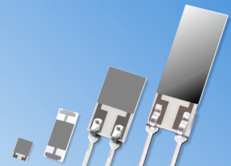 For example, for weather balloons and some other applications, an important requirement is high performance. Reducing the response time of the sensor is achieved by reducing the thickness of the polymer, thus the P14 Rapid provides a response time of less than 1.5 seconds. Another example is MK33 sensors designed to work with oils. Here, by increasing the area of the sensitive element, the steepness of the output characteristic increases, and hence the resolution of the sensor.
IST produces about a dozen different capacitive converters. Interested persons are invited to follow the link to their review , and we return to the digital HYT sensors.
The use of a “bare” sensing element is justified in very few cases. As a rule, it is simpler and more profitable to use an integrated module, in which, in addition to a capacitive converter, a temperature sensor, thermal compensation and signal processing circuits, as well as a digital or analog interface are already provided. These digital sensors are factory calibrated and do not require additional configuration.
Digital temperature and relative humidity sensors are available in different price segments. A sensor that fits the description in the previous paragraph can cost both $ 2 and $ 150. This difference between expensive and cheap sensors is explained by the fact that digital sensors differ not only in accuracy, speed and repeatability of measurement results, but also in other characteristics, which are not so simple to provide. This is long-term stability, the ability to use the sensor at very low or very high humidity and resistance to environmental influences. To understand why the listed characteristics have a big impact on the cost of the component, we turn to the features of production.
One of the main difficulties in the production of digital relative humidity sensors is the incompatibility of some processes for manufacturing a capacitive sensor and semiconductor manufacturing (creating a CMOS structure containing a temperature sensor, a signal processing circuit, etc.). Technologies do not allow fully preserving the characteristics of a capacitive converter if it is not made separately, but on the same substrate as the semiconductor structure. Therefore, the manufacture of a sensor that combines a capacitive element and a digital circuit always implies a compromise between the cost of production and the characteristics of the final product.
In the manufacture of HYT sensors, a capacitive SMD converter and an integrated circuit are manufactured separately from each other, separately tested, and only then installed on a common substrate and connected by wires.
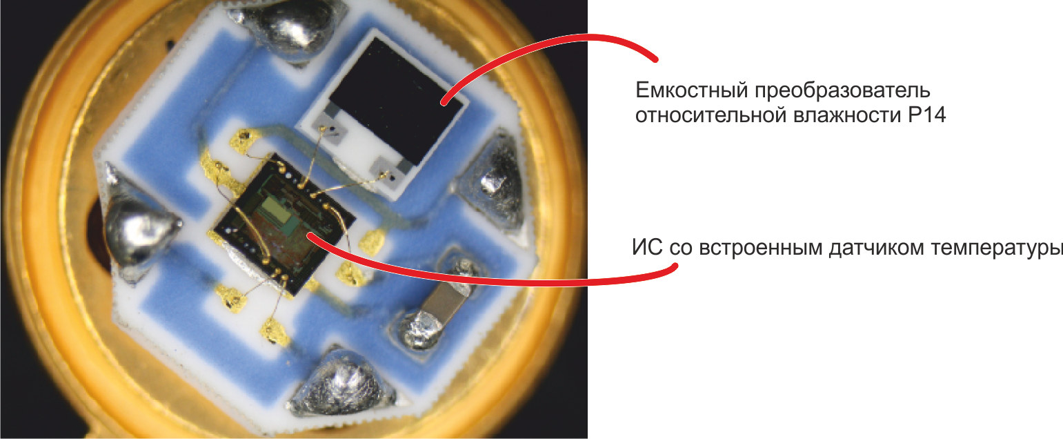
By reducing the mutual influence of the IC and the capacitive sensor, the use of materials that are almost not absorbing moisture, gold conductors, and the use of other measures to improve quality, it is possible to achieve accuracy on the digital module that is close to the accuracy of a separate humidity-capacity converter.
Standard factory calibration is carried out at nine points at three temperatures:
After calibration, control measurements are taken. Standard control points:
Here is the time to recall one of the main IST chips: at the request of the customer, the manufacturer makes a variety of modifications of its sensors. Sensors with changed characteristics are delivered, products in non-standard cases and, of course, sensors with non-standard calibration. Knowing the specifics of the conditions of use of the final product, you can, for example, order a HYT sensor with a calibration from 0 to 50% RH with a shift of + 2% RH over the entire range.
Such modifications have little effect on the price and delivery time, and, which is especially nice, are available for small items.
Here is a description of the HYT series sensors.
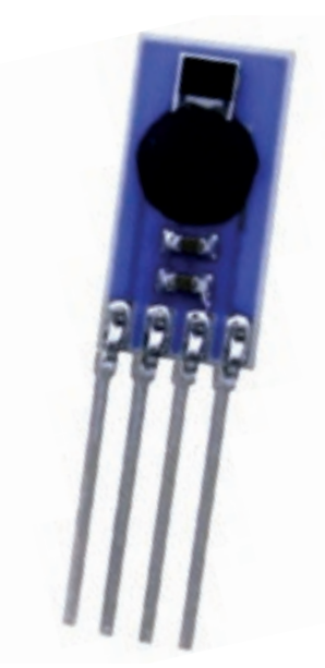 The simplest module - HYT 271 - has a size of 5 by 10 mm and consists of a capacitive converter filled with a “blot” of the integrated circuit and additional capacitors. In the absence of a protective filter, maximum performance and a minimum price are achieved.

 The HYT 221 digital sensor has the same filling as the HYT 271, but is covered with a protective filter that allows the sensor to be used even when there is a spray of water.
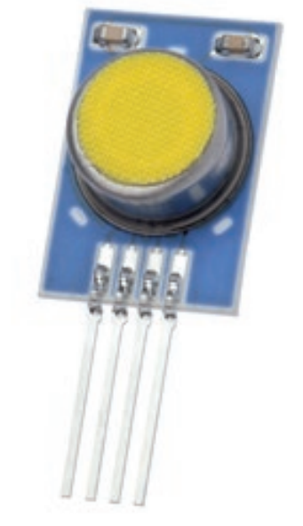
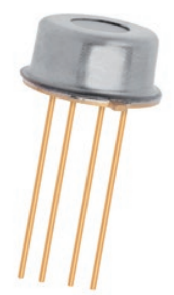 The HYT 939 sensor also differs only in the type of protective filter - the components are placed under a round metal case, on the upper side of which there is a hole closed by a membrane. The HYT 939 module, resistant to pressure up to 16 bar, is available for order.

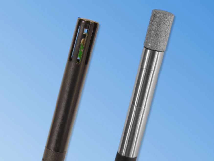 In accordance with customer requirements, both the structure and overall dimensions of the sensor can be changed. Instead of the standard I2C interface, the sensor can be equipped with a 5-pin SPI, and additional quasi-analog lines can be added to the digital interface. The sensor leads can be extended, equipped with a connector. Sensors are manufactured in specialized cases, such as in the photo.
Ordering sensors with modified sizes or non-standard configurations is also possible for small-scale production.
The standard interface for connecting the HYT sensor to the control microcontroller is the I2C bus. The controller is the master, the sensor is the slave unit.
There is nothing remarkable about the hardware characteristics of the sensor interface - speeds from 100 to 400 kHz and a standard 7-bit address on the bus are supported. The default address of the sensor is 0x28, the address can be changed to a value from 0x00 to 0x7F. Data is transmitted in MSB mode, i.e. high bits go first.
I see no reason to describe the operation of the I2C bus itself. I also miss the description of the typical switching scheme, the requirements of the HYT module for timing on I2C, the description of the procedure for changing the sensor address. All this can be found on Wikipedia and documentation .
Let us dwell on the procedure for collecting data from the HYT sensor - a sequence of two commands for controlling the module.
In the absence of requests from the microcontroller, the sensor is in sleep mode. Upon the arrival of the ‚Measuring Request '(MR) command, he wakes up, starts a measurement cycle and generates a data packet for the control controller. Data preparation takes from 60 to 100 ms, after which the ‚Data Fetch '(DF) command should be sent to the sensor, by which data from the output register of the sensor is transmitted to the microcontroller.
The ‚Measuring Request 'command does not mean reading or writing data. The command contains only the header packet — the addresses of the slave node and the RW bit set to “0”, ie on record.
The ‚Data Fetch '(DF) command is used to read data. The header file contains the address of the sensor and the RW bit set to “1”, i.e. to read.
The maximum number of bytes that must be received on the microcontroller is four. The first two bytes contain data on relative humidity, the third and fourth - about temperature.
The microcontroller can request only the first two bytes (only humidity data) or the first three bytes (humidity data and high-order bits of the temperature value).
Both humidity and temperature account for 14 bits. The Data Fetch package also contains two status bits:
Processing the received package consists in calculating the temperature and relative humidity from the input data. First, the status bits are masked, then the absolute values of temperature and relative humidity are calculated from the obtained data:
RH [%] = (100 / (2 14 - 1)) * RH in
T [° C] = (165 / (2 14 - 1) ) * T I - 40
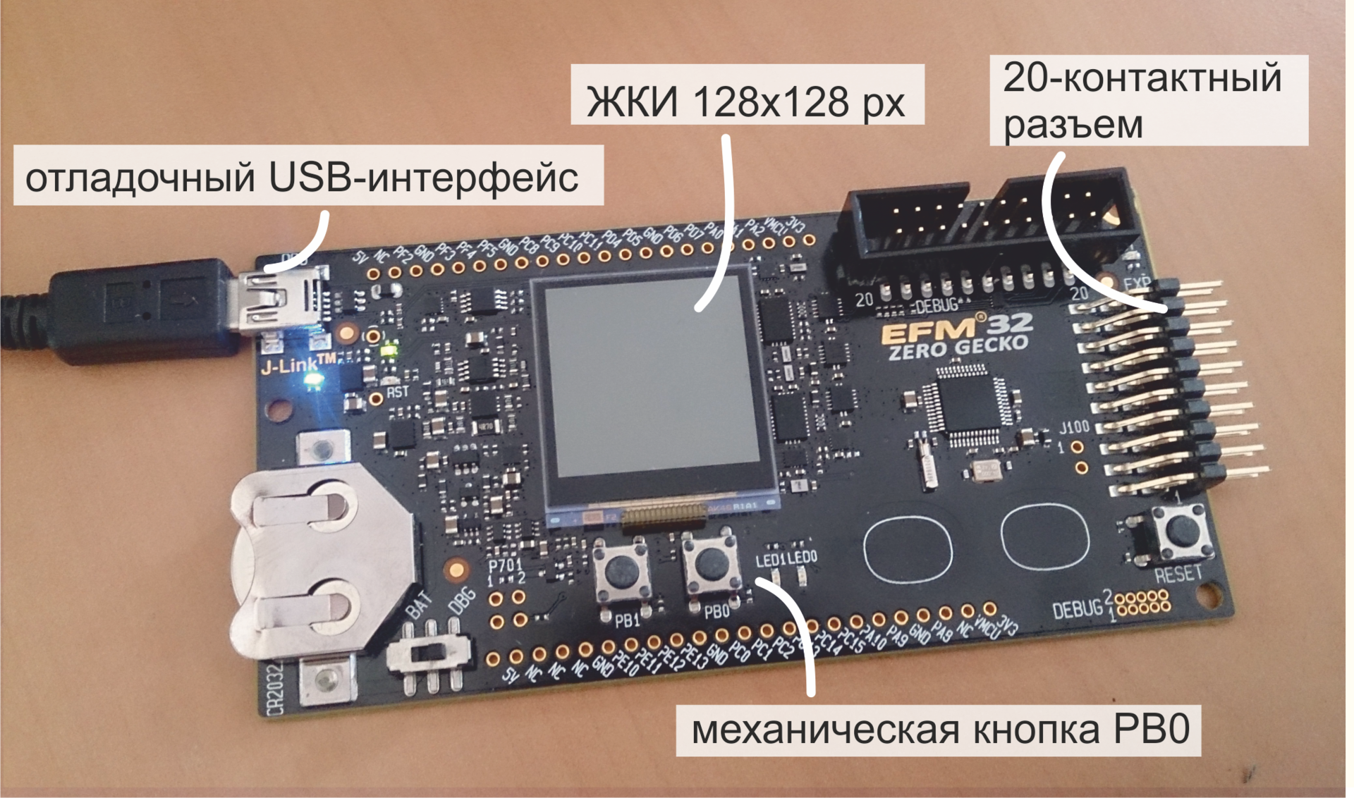
From theory to practice. Consider the task of polling a HYT sensor from an EFM32ZG-STK3200 debug board from Silicon Labs, a detailed description of which was given in a previous article .
This time, on the debug board, we need the built-in LCD display, a mechanical button and a 20-pin connector, on which I2C signals, power and ground are available.
Connection We
connect the lines in accordance with the pinout of the sensor and the board connector.
For the I2C bus to work, pull-up resistors must be provided on both of its lines. The documentation for HYT sensornominal values of 2.2 kOhm are indicated, and initially the circuit was assembled using two separate resistances. However, during debugging, it turned out that for polling a sensor connected to short leads, it is enough to use the built-in pull-up resistors of the EFM32 microcontroller. Their nominal value is 40 kOhm.

In this case, the sensor is powered by the MK power line (3.3 V), but five-volt levels are acceptable.
Microcontroller programming
To work with the EFM32ZG-STK3200 debug board, the Simplicity Studio environment is used - a platform containing IDEs, sample programs, documentation and various utilities for developing the application. Its description can also be found in previous articles., here I’ll just say that this is a free program that SiLabs distributes to work with SiLabs controllers.
When creating the program, the ready-made I2C driver from SiLabs and the glib library are used, designed to work with the built-in LCD plan. For communication with the display, the SPI interface and a real-time clock are used, however, work with these modules is hidden in the depths of glib.
The program implements the simplest algorithm for polling the HYT sensor - by pressing the PB1 button we get temperature and humidity data from the sensor, recalculate the obtained values in degrees Celsius and percent and display them on the screen. If an error occurred while receiving data, a corresponding message is displayed.


Full source code available on github. Below we analyze only that part of the program that is related to the polling of the sensor, i.e. to communication on I2C.
The standard library functions from Silicon Labs are mainly used - the main package em_i2c and its add-on i2cspm .
For communication with the sensor, i.e. implementations of the Measuring Request and Data Fetch commands, functions of the same name serve.
Each of them contains operations for forming a packet for I2C and a command for sending a packet. To form a packet, a structure of type I2C_TransferSeq_TypeDef is used, containing the sensor address, the value of the RW bit, and the format of the registers for receiving (buf [0]) and transmitting (buf [1]) data via I2C.
The performDFCommand function, in addition to indicating the reception of a four-byte packet with writing data to the I2CdataToRead array, contains an algorithm for processing the received message. As a result of conversion to temperature and humidity variables, the desired values are written.
When working with ready-made library functions for I2C from SiLabs, there are two main ways to ruin your life:
Method 1 : Calculate that 0x28 should be written in HYT_ADDR, i.e. Sensor address specified in the documentation .
Let me remind you that the address on the I2C bus is seven bits, i.e. by 0x28 in the documentation we mean 010 1000. It would be logical to supplement this number with the high bit “0” and still have 0x28, but for some reason the library function considers that the address is not the least, but the most significant 7 bits. Thus, instead of
Method 2 : Calculate that I2C_FLAG_READ is “0”, and I2C_FLAG_WRITE is “1”, which is stipulated by the bus protocol. That is, in fact, everything is so, in the header byte of the I2C package there is one single bit RW, which is set to "0" to write data and to "1" to read data. However, in the bowels of the em_lib library, such insidious defines hide:
Otherwise, there were no complaints about em_i2c and other em _ *** packages.
Between calls to the performMRCommand () and performDFCommand () functions, a delay must be provided for which the sensor generates a package with the measurement results.
The ReceiveDataAndShowIt () function that polls the sensor and displays measurement results is called from the interrupt handler, which is shown below.
It is important to note here that this program performs a very trivial task. To measure the temperature and humidity, which almost do not change over time, any inexpensive sensor is suitable.
The outstanding features of the HYT series are much better illustrated in dynamics. The video below shows how quickly the HYT-271 responds to changes in air humidity.
If you have ever had the honor of observing at what speed the conditional DHT22 reacts to changes in humidity, then, of course, you will feel the difference.
PS The process of creating a prototype, which is shown on video, is dedicated to the series of articles " How to Stop Being Afraid and Love mbed "
In conclusion, I traditionally thank the reader for his attention and remind you that questions about the use of the products that we write about on the Habré can also be sent to the email address specified in my profile.
The article is devoted to high-precision sensors of the HYT series. The description of the sensor device and the sensor element is given, the order of pairing the sensor with the microcontroller is described in detail, an example of development is given.
1. Overview
Standard HYT models are three sensors for measuring temperature and relative humidity, built on the basis of the same sensing element, but made in different cases.
We will talk about other packaging options below, but for now, we’ll give the main characteristics of the HYT sensors.
| Relative humidity | Temperature | |
| Measuring range | from 0 to 100% RH | -40 to +125 ° C |
| Accuracy (maximum accuracy) | ± 1.8% RH (in the range 0 ... 80% RH) | ± 0.2 ° C (in the range 0 ... 60 ° C) |
| Response time | HYT 271 <4 sec. HYT 221 <12 sec. HYT 939 <10 sec. | HYT 271 <5 sec. HYT 221 <12 sec. HYT 939 <10 sec. |
| Repeatability | ± 0.2% RH | ± 0.1 ° C |
| Hysteresis | <± 1% RH | |
| Long-term drift of characteristics | <± 0.5% RH / year | <± 0.05 ° C / year |
| Supply voltage | 2.7 - 5.5 V | |
| Current consumption | <22 μA at a sampling rate of 1 Hz, <1 μA in sleep mode | |
It is clear that such high accuracy and stability will not be useful in the home weather station tm . HYT sensors are used in industry - in household appliances, in processes that are related to drying, evaporation and distillation, in analyzers of residual moisture of various materials, in medical equipment, in ventilation systems and in other “critical applications”.
2. Sensitive element
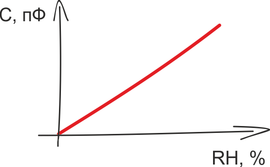
Like most modern RH sensors, HYT sensors have a capacitive sensor. The principles of operation of the humidity-capacity converters and their advantages are described in a huge number of sources, let me remind you the main thing.- The sensing element is a capacitor whose capacitance varies in proportion to the relative humidity of the environment.
- As a dielectric, a polymer layer is used, the dielectric constant of which depends on the amount of moisture absorbed by it.
- The dependence of moisture-capacity is linear in nature and allows measurements in the range from 0 to 100% RH.
The capacitive sensor is a ceramic substrate on which the lower conductive electrode, the moisture-absorbing polymer and the upper electrode are sequentially placed. The output characteristic of the converter is determined by the type of polymer, as well as its thickness and area:
εo is the electric constant. I’m too lazy to even give its value, the fact is that it is a constant
εr - Dielectric constant of the polymer, which varies in proportion to the amount of absorbed moisture
A - Area of the polymer
d - Thickness of the polymer
Depending on the purpose of the sensitive element, converters with different characteristics are produced based on polymers with various parameters.
IST produces about a dozen different capacitive converters. Interested persons are invited to follow the link to their review , and we return to the digital HYT sensors.
3. The structure of the sensors HYT
The use of a “bare” sensing element is justified in very few cases. As a rule, it is simpler and more profitable to use an integrated module, in which, in addition to a capacitive converter, a temperature sensor, thermal compensation and signal processing circuits, as well as a digital or analog interface are already provided. These digital sensors are factory calibrated and do not require additional configuration.
Digital temperature and relative humidity sensors are available in different price segments. A sensor that fits the description in the previous paragraph can cost both $ 2 and $ 150. This difference between expensive and cheap sensors is explained by the fact that digital sensors differ not only in accuracy, speed and repeatability of measurement results, but also in other characteristics, which are not so simple to provide. This is long-term stability, the ability to use the sensor at very low or very high humidity and resistance to environmental influences. To understand why the listed characteristics have a big impact on the cost of the component, we turn to the features of production.
One of the main difficulties in the production of digital relative humidity sensors is the incompatibility of some processes for manufacturing a capacitive sensor and semiconductor manufacturing (creating a CMOS structure containing a temperature sensor, a signal processing circuit, etc.). Technologies do not allow fully preserving the characteristics of a capacitive converter if it is not made separately, but on the same substrate as the semiconductor structure. Therefore, the manufacture of a sensor that combines a capacitive element and a digital circuit always implies a compromise between the cost of production and the characteristics of the final product.
In the manufacture of HYT sensors, a capacitive SMD converter and an integrated circuit are manufactured separately from each other, separately tested, and only then installed on a common substrate and connected by wires.
By reducing the mutual influence of the IC and the capacitive sensor, the use of materials that are almost not absorbing moisture, gold conductors, and the use of other measures to improve quality, it is possible to achieve accuracy on the digital module that is close to the accuracy of a separate humidity-capacity converter.
4. Calibration of HYT sensors
Standard factory calibration is carried out at nine points at three temperatures:
- 0% and 85% RH at 5 ° C
- 0%, 15%, 30%, 50%, 85% RH at 30 ° C
- 0% and 85% RH at 45 ° C
After calibration, control measurements are taken. Standard control points:
- 85% RH at 5 ° C
- 20% and 75% RH at 25 ° C
Here is the time to recall one of the main IST chips: at the request of the customer, the manufacturer makes a variety of modifications of its sensors. Sensors with changed characteristics are delivered, products in non-standard cases and, of course, sensors with non-standard calibration. Knowing the specifics of the conditions of use of the final product, you can, for example, order a HYT sensor with a calibration from 0 to 50% RH with a shift of + 2% RH over the entire range.
Such modifications have little effect on the price and delivery time, and, which is especially nice, are available for small items.
5. HYT Sensor Housing
Here is a description of the HYT series sensors.
Ordering sensors with modified sizes or non-standard configurations is also possible for small-scale production.
4. The procedure for pairing the sensor and the control controller
The standard interface for connecting the HYT sensor to the control microcontroller is the I2C bus. The controller is the master, the sensor is the slave unit.
There is nothing remarkable about the hardware characteristics of the sensor interface - speeds from 100 to 400 kHz and a standard 7-bit address on the bus are supported. The default address of the sensor is 0x28, the address can be changed to a value from 0x00 to 0x7F. Data is transmitted in MSB mode, i.e. high bits go first.
I see no reason to describe the operation of the I2C bus itself. I also miss the description of the typical switching scheme, the requirements of the HYT module for timing on I2C, the description of the procedure for changing the sensor address. All this can be found on Wikipedia and documentation .
Let us dwell on the procedure for collecting data from the HYT sensor - a sequence of two commands for controlling the module.
In the absence of requests from the microcontroller, the sensor is in sleep mode. Upon the arrival of the ‚Measuring Request '(MR) command, he wakes up, starts a measurement cycle and generates a data packet for the control controller. Data preparation takes from 60 to 100 ms, after which the ‚Data Fetch '(DF) command should be sent to the sensor, by which data from the output register of the sensor is transmitted to the microcontroller.
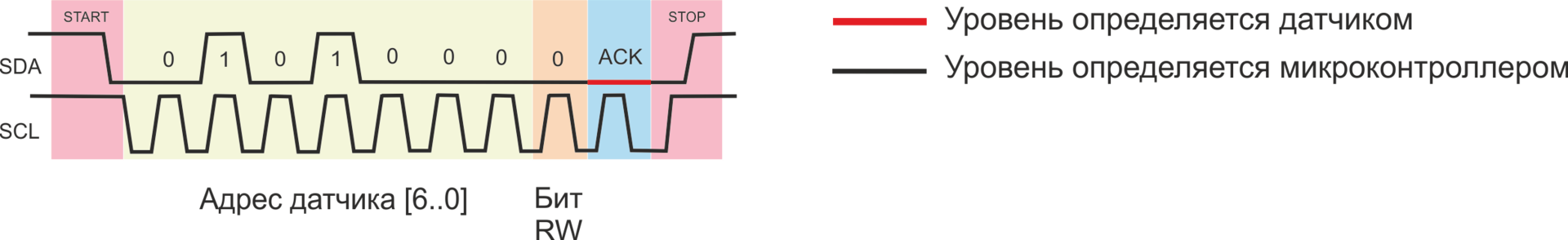
The ‚Measuring Request 'command does not mean reading or writing data. The command contains only the header packet — the addresses of the slave node and the RW bit set to “0”, ie on record.
The ‚Data Fetch '(DF) command is used to read data. The header file contains the address of the sensor and the RW bit set to “1”, i.e. to read.
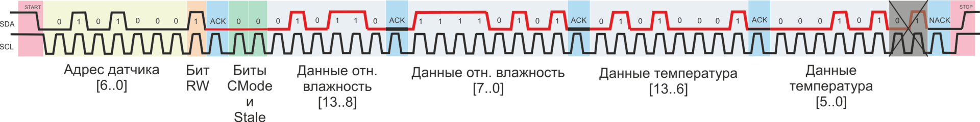
The maximum number of bytes that must be received on the microcontroller is four. The first two bytes contain data on relative humidity, the third and fourth - about temperature.
The microcontroller can request only the first two bytes (only humidity data) or the first three bytes (humidity data and high-order bits of the temperature value).
Both humidity and temperature account for 14 bits. The Data Fetch package also contains two status bits:
- CMode Bit. If "1" is set, then the sensor is in command mode - in the service mode, which is used to change the sensor address to I2C
- Stale bit. If “1” is set, then after the next measurement cycle, the same temperature and humidity values are obtained as after the previous cycle
Processing the received package consists in calculating the temperature and relative humidity from the input data. First, the status bits are masked, then the absolute values of temperature and relative humidity are calculated from the obtained data:
RH [%] = (100 / (2 14 - 1)) * RH in
T [° C] = (165 / (2 14 - 1) ) * T I - 40
5. Example of turning on the HYT sensor
From theory to practice. Consider the task of polling a HYT sensor from an EFM32ZG-STK3200 debug board from Silicon Labs, a detailed description of which was given in a previous article .
This time, on the debug board, we need the built-in LCD display, a mechanical button and a 20-pin connector, on which I2C signals, power and ground are available.
Connection We
connect the lines in accordance with the pinout of the sensor and the board connector.
For the I2C bus to work, pull-up resistors must be provided on both of its lines. The documentation for HYT sensornominal values of 2.2 kOhm are indicated, and initially the circuit was assembled using two separate resistances. However, during debugging, it turned out that for polling a sensor connected to short leads, it is enough to use the built-in pull-up resistors of the EFM32 microcontroller. Their nominal value is 40 kOhm.
In this case, the sensor is powered by the MK power line (3.3 V), but five-volt levels are acceptable.
Microcontroller programming
To work with the EFM32ZG-STK3200 debug board, the Simplicity Studio environment is used - a platform containing IDEs, sample programs, documentation and various utilities for developing the application. Its description can also be found in previous articles., here I’ll just say that this is a free program that SiLabs distributes to work with SiLabs controllers.
When creating the program, the ready-made I2C driver from SiLabs and the glib library are used, designed to work with the built-in LCD plan. For communication with the display, the SPI interface and a real-time clock are used, however, work with these modules is hidden in the depths of glib.
The program implements the simplest algorithm for polling the HYT sensor - by pressing the PB1 button we get temperature and humidity data from the sensor, recalculate the obtained values in degrees Celsius and percent and display them on the screen. If an error occurred while receiving data, a corresponding message is displayed.
Full source code available on github. Below we analyze only that part of the program that is related to the polling of the sensor, i.e. to communication on I2C.
The standard library functions from Silicon Labs are mainly used - the main package em_i2c and its add-on i2cspm .
For communication with the sensor, i.e. implementations of the Measuring Request and Data Fetch commands, functions of the same name serve.
Each of them contains operations for forming a packet for I2C and a command for sending a packet. To form a packet, a structure of type I2C_TransferSeq_TypeDef is used, containing the sensor address, the value of the RW bit, and the format of the registers for receiving (buf [0]) and transmitting (buf [1]) data via I2C.
/**************************************************************************//**
 * Start a measuring cycle (Measurement Request command)
 *  - [6-bit address] + [W flag]
 *  - w/o data transfer
 *****************************************************************************/
void performMRCommand(void) {
	I2C_TransferSeq_TypeDef seq;
	seq.addr = HYT_ADDR;
	seq.flags = I2C_FLAG_WRITE;
	seq.buf[0].len = 0;
	seq.buf[1].len = 0;
	I2CSPM_Transfer(I2C0, &seq);
}
The performDFCommand function, in addition to indicating the reception of a four-byte packet with writing data to the I2CdataToRead array, contains an algorithm for processing the received message. As a result of conversion to temperature and humidity variables, the desired values are written.
/**************************************************************************//**
 * Fetch the last measured value of Humidity / Temperature (Data Fetch command)
 *  - [6-bit address] + [R flag]
 *  - w/ 4-byte data transfer: [CMode bit] + [State bit] + [14 bit humididty] +
 * 								+ [14 bit temeprature] + [2 insignificant bits]
 *****************************************************************************/
int8_t performDFCommand(void) {
	I2C_TransferSeq_TypeDef seq;
	uint8_t I2CdataToRead[4];
	unsigned int tempRawData, humididtyRawData;
	seq.addr = HYT_ADDR;
	seq.flags = I2C_FLAG_READ;
	seq.buf[0].data = I2CdataToRead;
	seq.buf[0].len = 4;
	seq.buf[1].len = 0;
	I2CSPM_Transfer(I2C0, &seq);
	uint8_t sensorCModeBit = (I2CdataToRead[0] & 0x80) >> 7;
	uint8_t sensorStateBit = (I2CdataToRead[0] & 0x40) >> 6;
	tempRawData = ((I2CdataToRead[2] << 8) | I2CdataToRead[3]) >> 2;
	humididtyRawData = ((I2CdataToRead[0] & 0x3F) << 8) | I2CdataToRead[1];
	if (sensorCModeBit == 1) {
		return HYT_COMMAND_MODE;
	}
	if (tempRawData != 0 && humididtyRawData != 0 && tempRawData < 0x3FFF
			&& humididtyRawData < 0x3FFF) {
		if (sensorStateBit != 1) {
			/* temperature as 14bit-value in the range from -40°C to +125°C */
			temperature = ((float) (tempRawData) * 165.0F / 16383.0F) - 40.0F;
			/* humidity as 14bit-value in the range from 0%rH to 100%rH */
			humidity = (float) humididtyRawData * 100.0F / 16383.0F;
		} else {
			/* No new value has been created since the last reading */
		}
		return HYT_IS_OK;
	} else {
		return HYT_ERROR;
	}
}
When working with ready-made library functions for I2C from SiLabs, there are two main ways to ruin your life:
Method 1 : Calculate that 0x28 should be written in HYT_ADDR, i.e. Sensor address specified in the documentation .
Let me remind you that the address on the I2C bus is seven bits, i.e. by 0x28 in the documentation we mean 010 1000. It would be logical to supplement this number with the high bit “0” and still have 0x28, but for some reason the library function considers that the address is not the least, but the most significant 7 bits. Thus, instead of
#define HYT_ADDR 0x28
#define HYT_ADDR 0x50
#define HYT_ADDR 0x51
Method 2 : Calculate that I2C_FLAG_READ is “0”, and I2C_FLAG_WRITE is “1”, which is stipulated by the bus protocol. That is, in fact, everything is so, in the header byte of the I2C package there is one single bit RW, which is set to "0" to write data and to "1" to read data. However, in the bowels of the em_lib library, such insidious defines hide:
#define 	I2C_FLAG_WRITE    0x0001
#define 	I2C_FLAG_READ     0x0002
Otherwise, there were no complaints about em_i2c and other em _ *** packages.
Between calls to the performMRCommand () and performDFCommand () functions, a delay must be provided for which the sensor generates a package with the measurement results.
/**************************************************************************//**
 * Read temperature and humidity from HYT sensor, show result on the display
 *  - Send MR (Measurement Requests) command
 *  - Wait for 100 msec
 *  - Send DF (Data Fetch) command
 *  - Show result OR show error message
 *****************************************************************************/
void ReceiveDataAndShowIt(void) {
	performMRCommand();
	delay100ms();
	int8_t HYT_result = performDFCommand();
	if (HYT_result == HYT_IS_OK) {
		Display_ShowValues(temperature, humidity);
	} else if (HYT_result == HYT_COMMAND_MODE) {
		Display_ShowCMode();
	} else if (HYT_result == HYT_ERROR) {
		Display_ShowError();
	}
}
The ReceiveDataAndShowIt () function that polls the sensor and displays measurement results is called from the interrupt handler, which is shown below.
/**************************************************************************//**
 * GPIO Interrupt handler (pushbutton # 1)
 *  - Receive HYT data & show results on the display
 *****************************************************************************/
void GPIO_ODD_IRQHandler(void) {
	uint32_t interruptMask = GPIO_IntGet();
	if (interruptMask & (1 << BUTTON_PIN)) {
		Display_WellcomeScreen();
		ReceiveDataAndShowIt();
	}
	GPIO_IntClear(interruptMask);
}
It is important to note here that this program performs a very trivial task. To measure the temperature and humidity, which almost do not change over time, any inexpensive sensor is suitable.
The outstanding features of the HYT series are much better illustrated in dynamics. The video below shows how quickly the HYT-271 responds to changes in air humidity.
If you have ever had the honor of observing at what speed the conditional DHT22 reacts to changes in humidity, then, of course, you will feel the difference.
PS The process of creating a prototype, which is shown on video, is dedicated to the series of articles " How to Stop Being Afraid and Love mbed "
6. Conclusion
In conclusion, I traditionally thank the reader for his attention and remind you that questions about the use of the products that we write about on the Habré can also be sent to the email address specified in my profile.