Self-made laser installation "Lightsaber": as it were. Part 2
Disclaimer: this project was carried out because of my great love for the art of receiving laser radiation, in many respects for the process of its implementation, therefore I will ask not to ask the question “why is this necessary” in the comments. The information presented below is for informational purposes only; the author is not responsible for the consequences of attempts to repeat the above described
summary of the first part :
What happened next? Look under the cut.
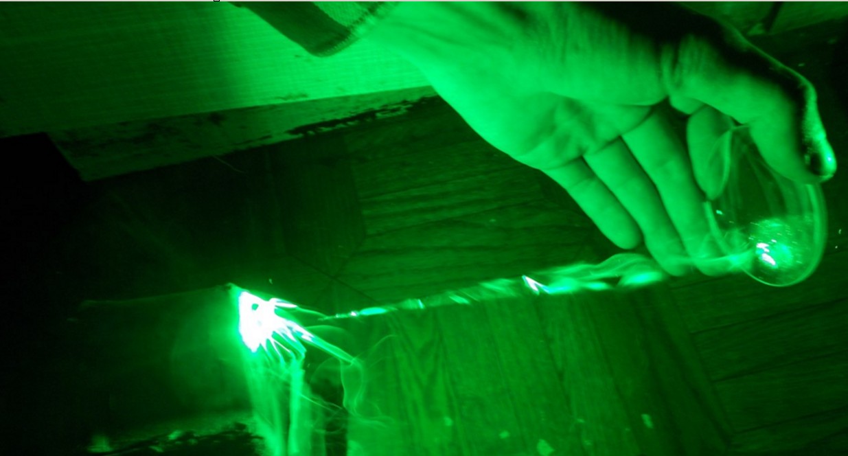
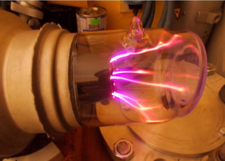
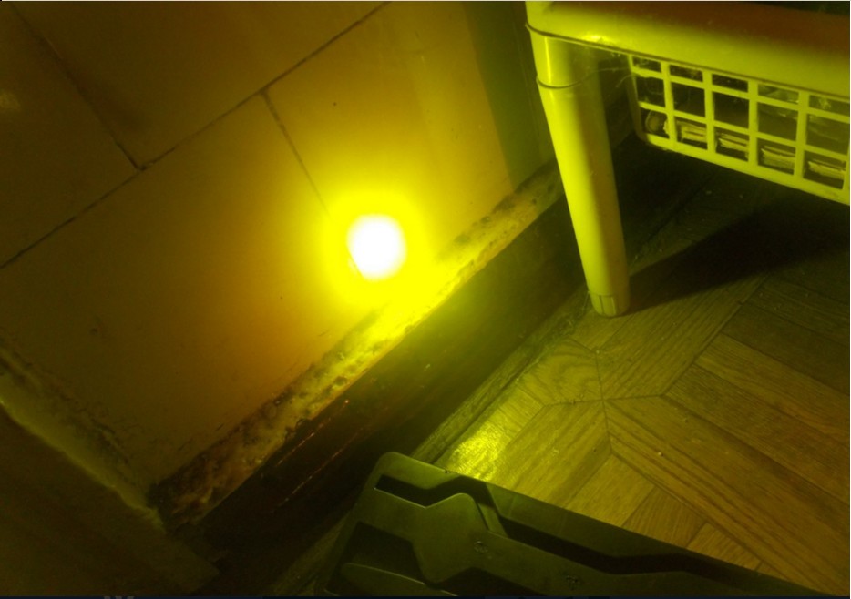
Suspension of the project was due to the leakage of the active element of the UL-102. The active element was deposited in working condition, after 2 months it was found sticking. Judging by the steady-state gas pressure in it, the leakage was very slow, since it still could burn the streamer discharge of a characteristic form, but it was not ignited along the discharge channel. An attempt to find a leak was not successful. And all this despite the fact that the frame has already been assembled for this particular type of active element, and the installation of another type is impossible there.
This was how discharges in AE looked after it flowed.
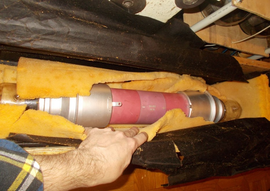
There was no choice but to look for a new UL-102. I had to mobilize all my connections in various research institutes and laser laboratories in different cities, but it did bring a new result - a new active element was obtained, also a new one, in a factory box. At the same time he was more recent year of release.
Unpacking a new AE:
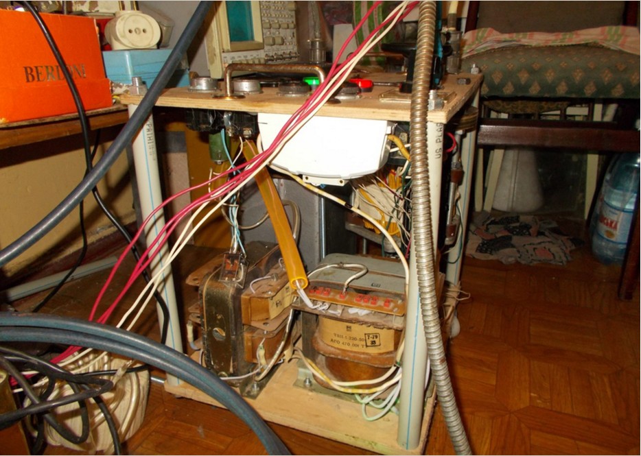
During the search for a new AE, I managed to get acquainted with a good specialist in the power supply system of the LML, who pointed out a number of my mistakes. The new AE was immediately installed in the finished emitter and the experiments were continued. The “direct excitation scheme” was returned again as the simplest, but with slight modifications of the grid circuit of the thyratron, which allowed increasing the stability of its operation to the level of the Blumlein generator, but still not enough. And again the epic failure - during long-term work at the rated power, the secondary winding of one of the power transformers IVN burned down, which was accompanied by the release of a huge cloud of yellow acrid smoke. As a temporary solution, these transformers were replaced by high-voltage transformers from the Soviet microwaves (also a legacy of my construction).
"A temporary solution to the transformer issue." The price for this was a reduction in the achievable anode voltage.
The burned-down transformer was disassembled in order to preserve its iron for winding a new one. This photo clearly shows the reason for overheating - good winding insulation. It was enough to exceed the current collection (which for Soviet transformers can be exceeded by 20-30%), as the winding is easily overheated. I have never met that the rest of the window in the gland (almost 1 cm on each side and 5 mm from the sides) was filled with epoxy ...

There remained one problem with the power source, which could not be overcome at this moment, namely, the poor stability of the operation of the thyratron in the operating mode region. Generation is still possible to get, but to maintain a long-term normal operation of the laser is already very difficult. A review of many articles in scientific journals made it possible to assert that the cause is the excess of the reverse voltage at the anode of the thyratron at the moment of its locking. The peculiarity of pulsed hydrogen thyratrons is that the maximum reverse voltage, for example, 25 kV for Тг700 \ 25 and Тги1000 \ 25, can be applied only 25 microseconds after the current through the thyratron stops, when all the plasma has already absorbed. It was quite logical to assume that this rule is not violated, since the ESR is 10 kHz, which means that the “gap” between pulses is 100 μs. But I did not take into account one factor. Plasma arc discharge inside a thyratron is inert. If not all, then many probably remember that if you look at the storyboard of the extinction of an arc lit on a large transformer substation, you can see that the arc does not disappear instantly, but over the course of several frames the video gradually splits into separate scraps, which then gradually fade away. The same thing happens in a pulsed hydrogen thyratron - after the current (locking) is stopped, the arc discharge also cools relatively slowly, breaking up into shreds, then disappears completely. Only after the end of this process can 25 kV reverse voltage be applied to it. If this is done earlier, then a new, unauthorized breakdown of the thyratron in the opposite direction will occur, and this will cause a fault of the IVN and the activation of its current protection. Or rather, not everything is so infernal. At the time of resorption of the discharge (before the expiration of the specified 25 µs post-pulse), the reverse voltage can be applied, and the thyratron will not break through. But only 5 kilovolts. Consequently, when a thyratron is operating in a copper vapor laser pumping scheme, this voltage is exceeded due to various non-stationary processes at the time of thyratron closure. Moreover, it becomes the greatest precisely when copper appears in the laser discharge, which greatly changes the characteristics of the AE as a load for the generator, which leads to a mismatch. when a thyratron is operating in a copper vapor laser pumping circuit, this voltage is exceeded due to various non-stationary processes at the moment of closure of the thyratron. Moreover, it becomes the greatest precisely when copper appears in the laser discharge, which greatly changes the characteristics of the AE as a load for the generator, which leads to a mismatch. when a thyratron is operating in a copper vapor laser pumping scheme, this voltage is exceeded due to various non-stationary processes at the moment of closure of the thyratron. Moreover, it becomes the greatest precisely when copper appears in the laser discharge, which greatly changes the characteristics of the AE as a load for the generator, which leads to a mismatch.
Many ways have been tried to eliminate this phenomenon by optimizing matching in different operating modes, but the radical result did not work - the conditions that gave stable operation on the mode of generation of radiation turned out to be unsuitable for heating mode and vice versa. The radical decision was only a change in the topology of the power unit, with the addition of new elements.
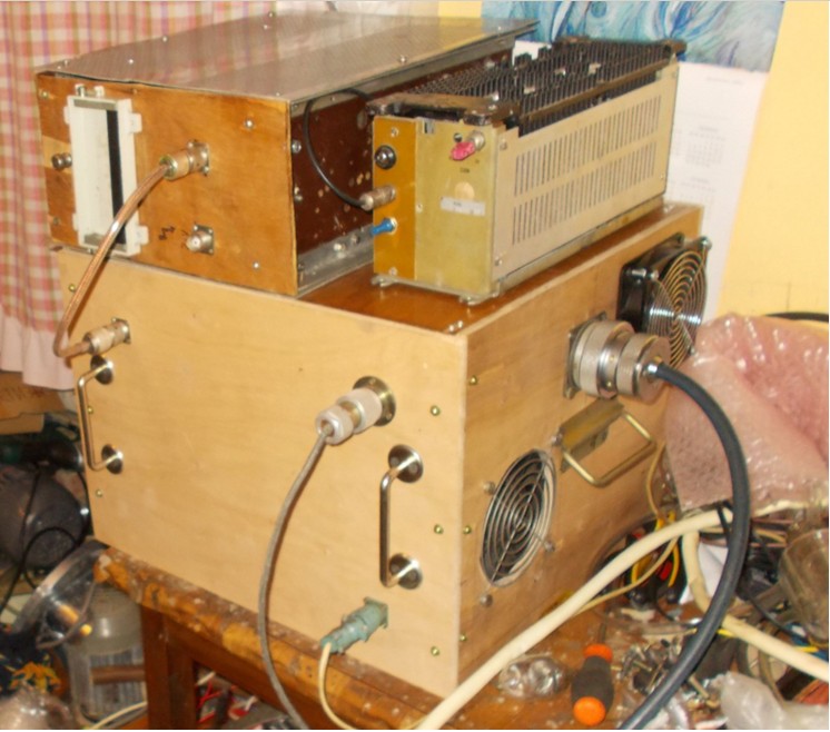
The circuit of the power unit was again converted to the seemingly promising scheme of the “controlled Arkadyev-Marx generator” on two thyratrons. This promised the use of again more simple and accessible TGI1-700 \ 25 thyratrons without an overload on the dissipated power at the anode. The generator of the control pulse was redone for this purpose in order to simultaneously unlock 2 thyratrons. The idea of the updated scheme was that there are 2 capacitors in it, which are in parallel at the moment of charge, and at the moment of unlocking the two thyratrons simultaneously, these capacitors are connected in series, as a result of which their voltages are added and applied to the AE electrodes. It also promised some improvement in the steepness of the pulse front on the AE and the resulting increase in the output radiation power, as the instantaneous voltage amplitude across the electrodes increased. A new layout of the power unit was assembled, which looked like this:
And on the diagram, it still looks pretty simple, although there are more details.

The tests showed the complete inoperability of the circuit in my performance - the thyratrons opened at odds with each other. Maybe I did something wrong. After that, I decided to change the topology of the power unit again, after consulting with a specialist. So, the modified Blumlein generator. It is almost identical to the usual Blumlein generator, but several more elements have been added to it. Namely, the so-called "chain of magnetic compression of the pulse." The essence of her work is that the amplitude of the flowing pulsed current through the saturable choke at the time of saturation of the choke increases sharply. Since the amount of energy transferred by one pulse is limited, and the initial pulse duration is also limited, then at the moment of saturation of the inductor and the increase of the current in the circuit - this portion of energy is nothing but to “shrink” in time, accordingly, the current pulse on the AE (laser tube) is significantly reduced. And if so, then the duration of the current pulse passing through the thyratron can be increased, and the duration of the pulse on the laser tube can be reduced, and most importantly, the front slope of the AE can be increased and the output radiation power can be raised. It looks very tempting.
This is how the diagram I assembled with the given par values.
The L2 choke stretches the current pulse through the thyratron in time, and the L4 choke is the saturable choke for the “magnetic compression” of the pulse on the laser tube. And this scheme finally began to work stably! The result definitely justified the effort expended on manufacturing the nonlinear throttle. I’ll stop here a little more. Again, I decided to repeat the construct described in the literature. And there it was proposed to make a choke consisting of one “coil” of a thick copper tube passed through 120 small ferrite ringlets. A piece of copper pipe with a diameter of 12mm was purchased in a store for refrigerators. Were bought ferrite rings with a small margin. The matter remained for small - to string them on the tube. Stringing them all in one time was irrational - it turned out too long sausage. Then I decided to make two pieces of tube, string them on 60 rings and fold U-shaped. Easier said than done. The fact is that the tube is not ideally smooth, and in the rings the diameter is slightly, in tenths of a millimeter, but it is different. There were even rings in which the hole was tapered or elliptical. And one and the other at the same time.
Attempting to pull the ring by force led to its instant splitting into pieces. About half put on freely, without problems. Then I had to process the copper tube with the sandpaper, until the next rings started to climb. Then again skin, put on again ... And so repeat until the bitter end. The result was such a construction.
It was installed in the new layout of the power unit.
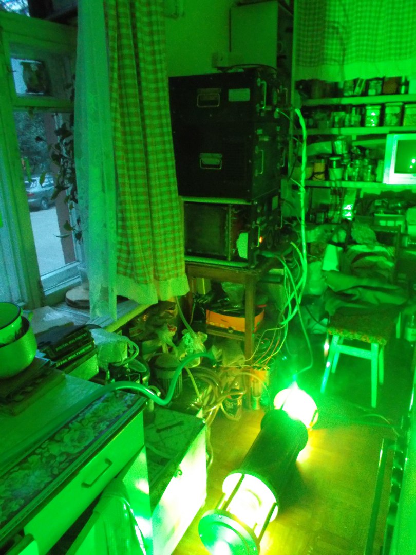
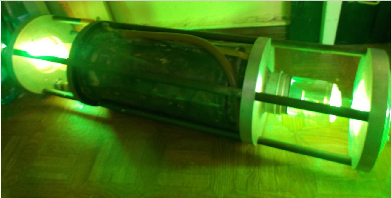
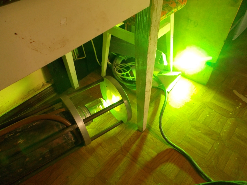
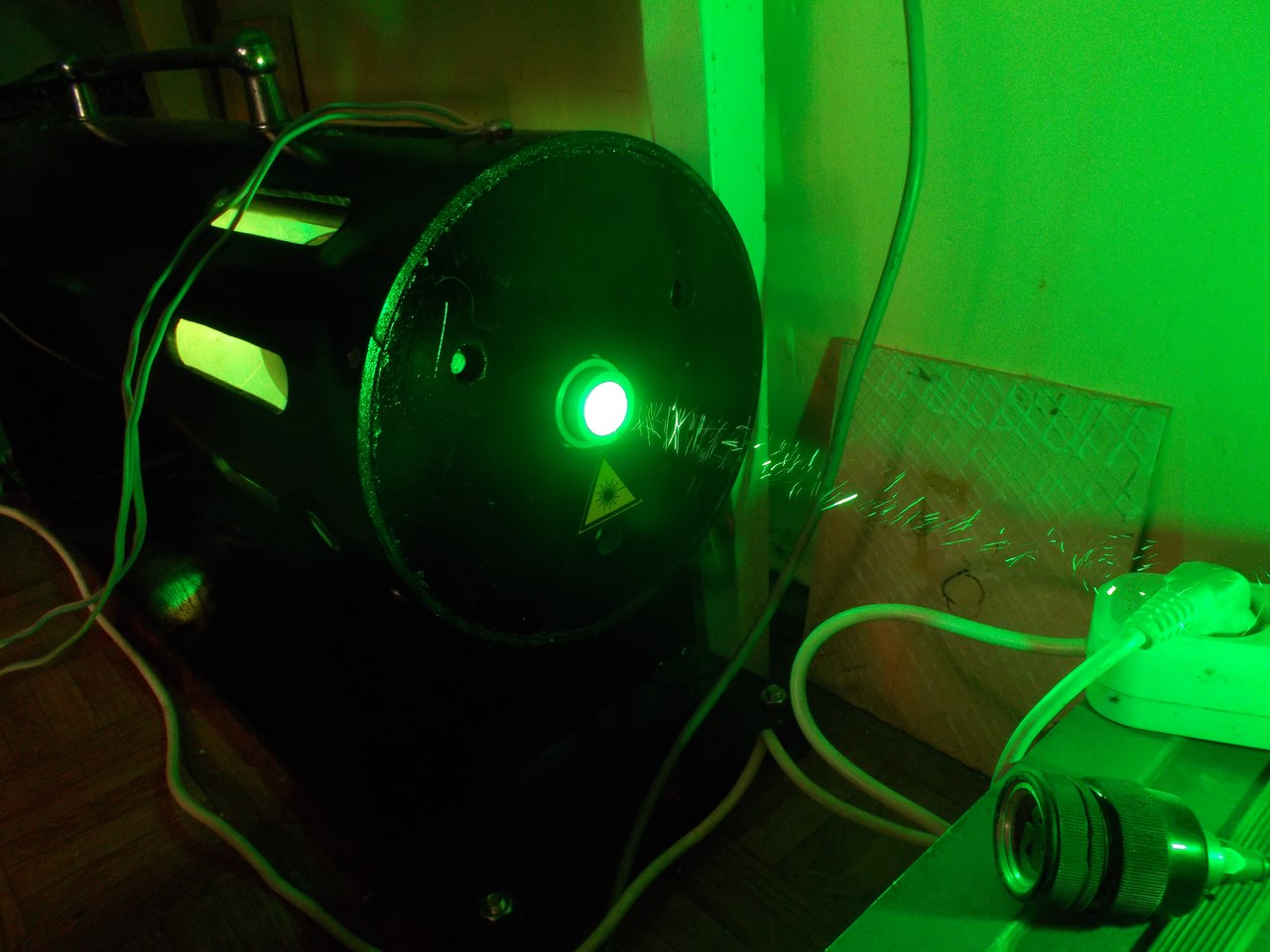
Installation is running. The laser warms up. For half an hour, no protection operation. This is a success! Finally, spontaneous emission of copper appears, followed by weak generation. Then the tuning of the mirrors of the resonator. And the room is illuminated by a powerful laser beam of poisonous green color!
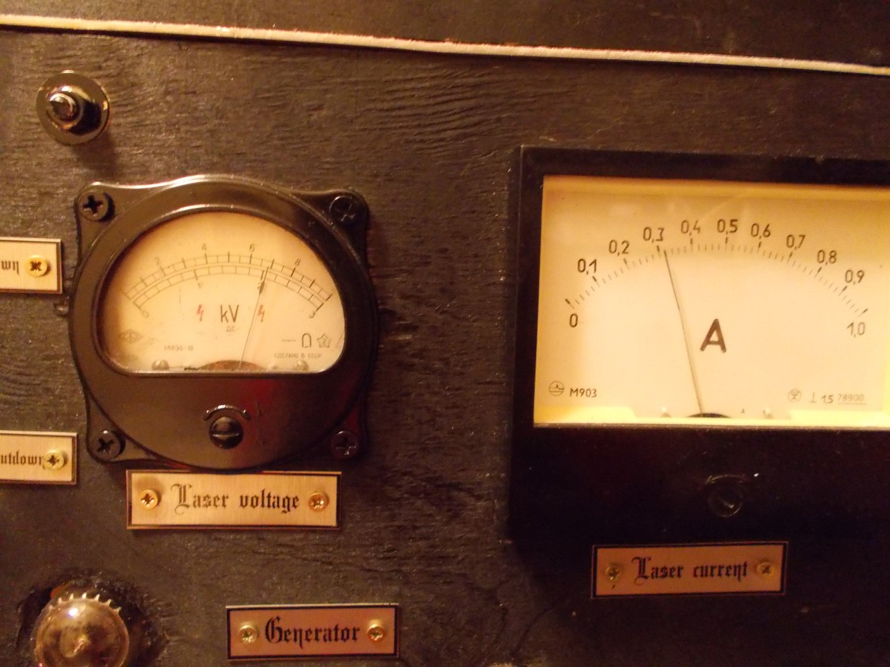
The light spot on the white tiled wall is so bright that the whole room is brightly lit. And while the brightness of the glow continued to increase, until it reached a constant value. As the brightness increased, the color of the beam from poisonous green to green lemon changed, which indicated the effective generation of the yellow line. The radiation power exceeded the previously obtained at least several times, the lower limit was assumed to be not less than 3 watts. With a power consumption of 1800 watts.

The beam transmitted through the lens is already very vigorously burning on the cardboard.
Tests of the laser are on video:
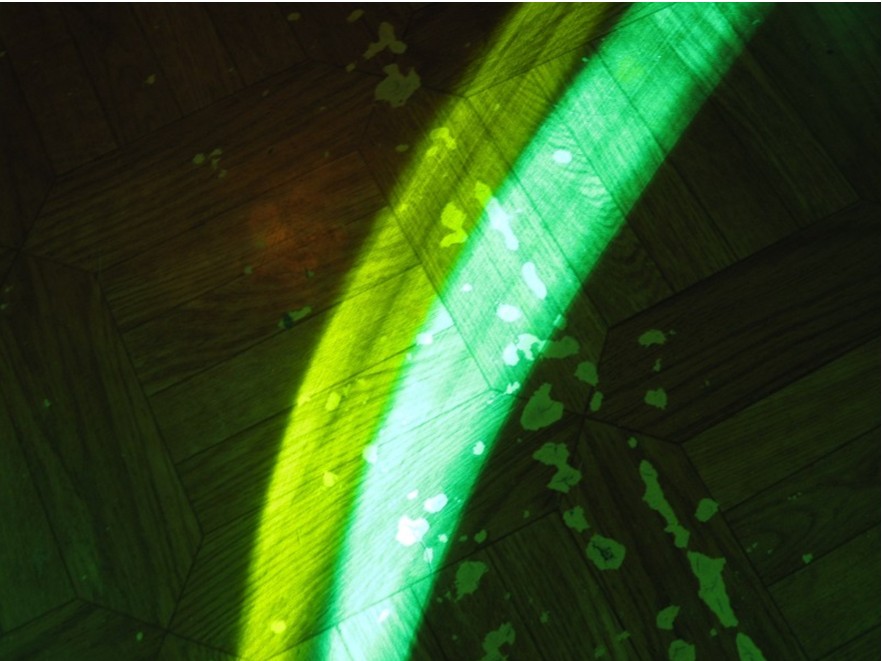
The laser beam is clearly visible. Its diameter corresponds to the diameter of the discharge channel, 20 mm.

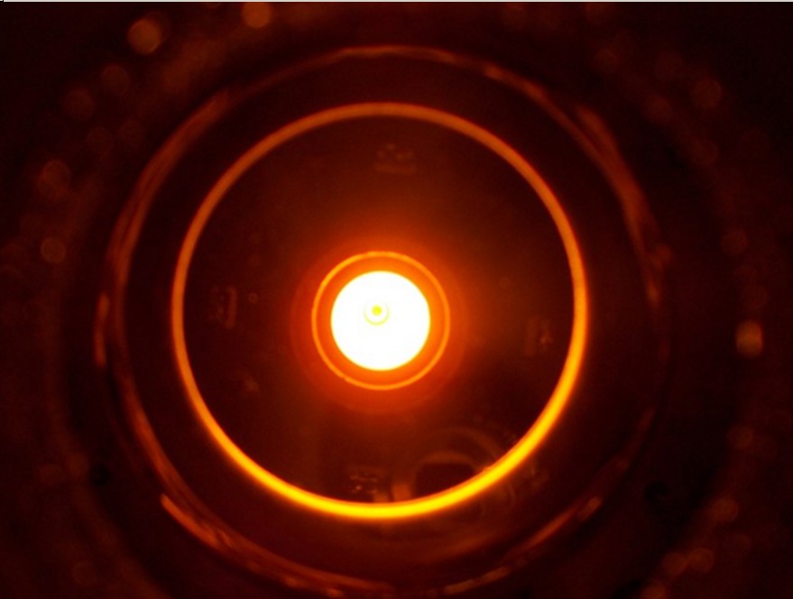
The discharge channel inside the AE at the operating temperature is almost white hot.
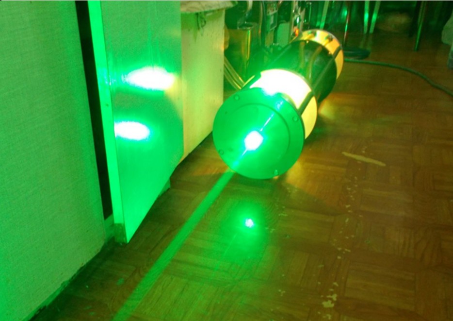
The laser beam is clearly visible in a lit room.
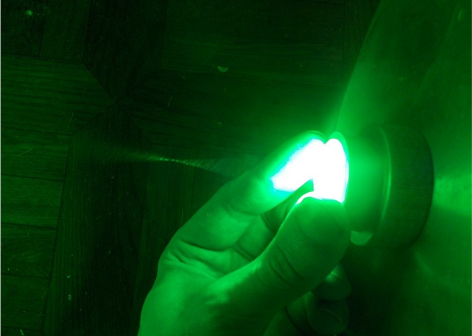
Behind the short-focus lens, the cone is beautifully visible, first converging before the focus of the beam, then diverging (area of the waist) of the rays. Combustible items in the focus is better not to put.
With the help of a fragment of a CD-ROM, you can expand the beam into a spectrum. It clearly shows that the beam has green and yellow lines, while the yellow has become much more powerful than before.
The yellow line can be identified separately by a filter that blocks the green light, namely, orange.
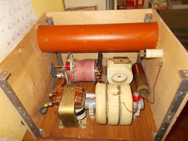
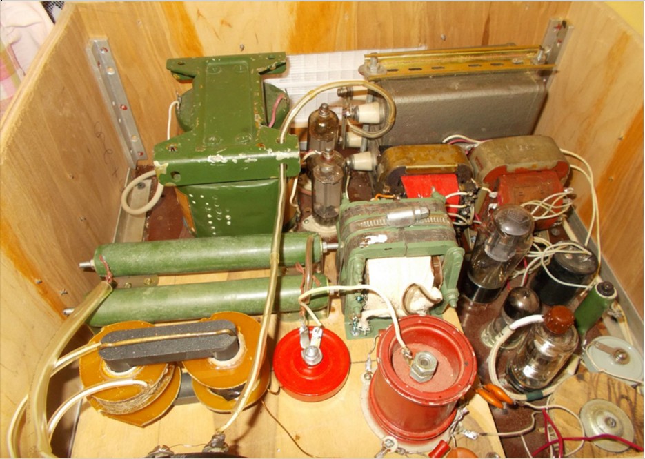
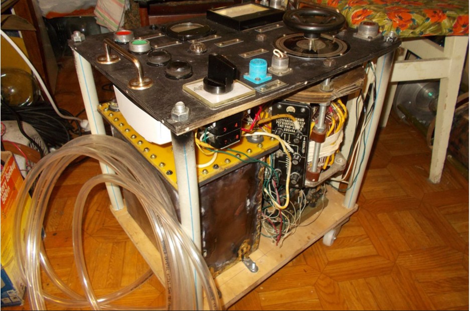
Now you could exhale and begin the transition from the layout to the finished product. The first in the case was packed power unit. Wood and plywood were chosen as materials for the hull, such as those that are most easily handled using a home electric tool. All elements were placed on a compact base, the magnetic compression choke was hidden in a section of sewer pipe and blown through by a fan. The anode of the thyratron is blown by its fan. And so that the hot air does not accumulate in a closed case, the third most powerful fan is installed, creating a draft inside the unit. During the installation of the components, it looked like this.
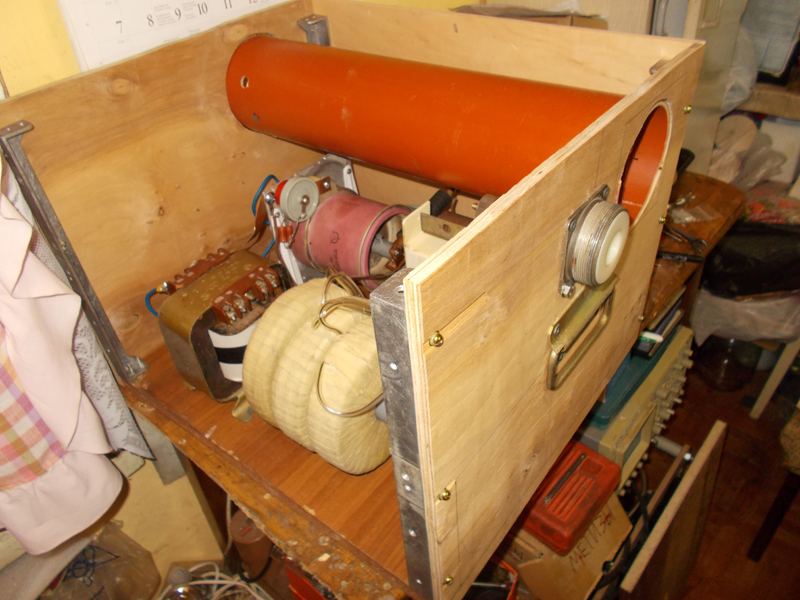
And in the collection - like this.
Next was a control generator packed for a power thyratron grid. The master oscillator and amplifier moved to a common body, made so that its width and depth were equal to the width and depth of the power unit.
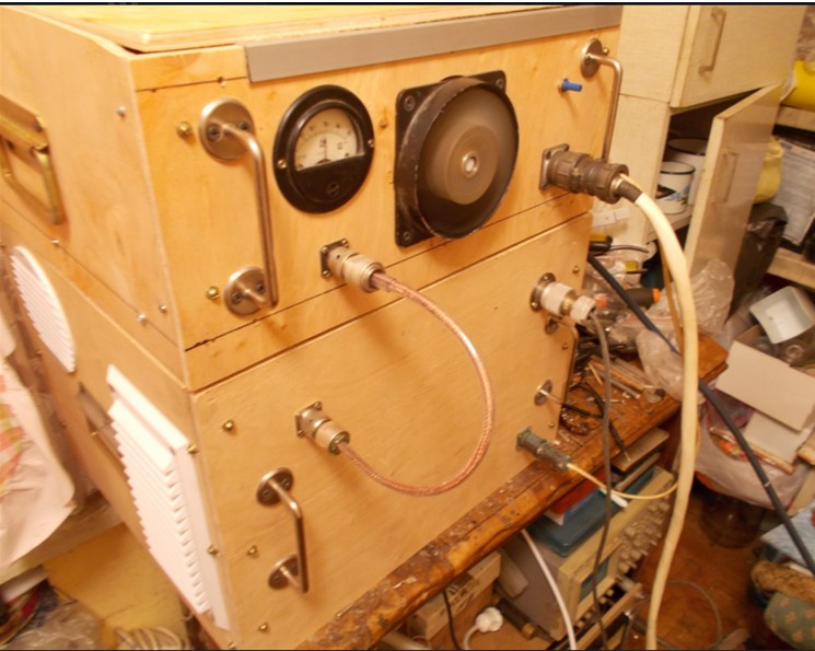
Began to get something like a dashboard. The IVN unit was, in general, already ready, it took only side walls to be added. At the same time, the exterior decoration of the blocks continued - it was decided to paint them black.

Ready stand turned out so.

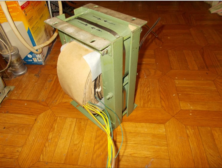
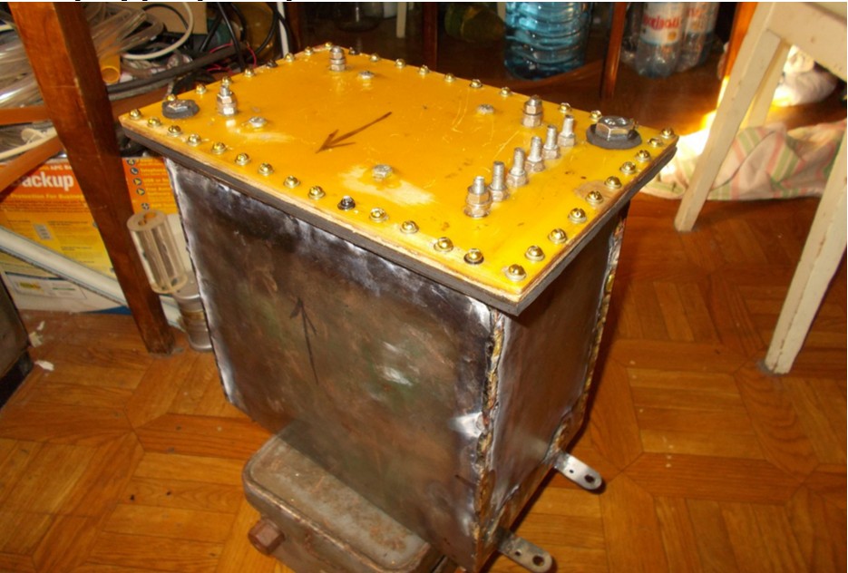
And yet I was haunted by the feeling that the work of the laser could still be improved, even more radiation power could be increased. Since inside the IVN, there still remained “temporary” transformers from microwaves, which did not allow obtaining an output voltage of more than 5 kV after the rectifier. It was a volitional decision - to make a completely new high-voltage transformer with oil insulation and water-cooled. The task was set: output alternating voltage 7 kV, continuous output current - 400 mA. From the secondary winding decided to make taps every 500V, starting with a voltage of 4.5 kV. Calculations showed that it is possible to use a core from a burned-out transformer, while the window was completely filled. First, I wound the transformer itself.
Then he was strengthened to the textolite plate, through which all the conclusions came out.
Then a tank was made of the sheet iron found at the acceptance of scrap.
Inside is a coil for cooling the oil.
Then the transformer was assembled.
And installed on his place.
Launching a laser with a new transformer made it possible to increase the power to about 5 watts! Those. It turned out to be the full equivalent of the factory setting mentioned at the beginning of the article. Only smaller dimensions, weight and with less energy consumption.
At full power, the color of the beam becomes more yellow.
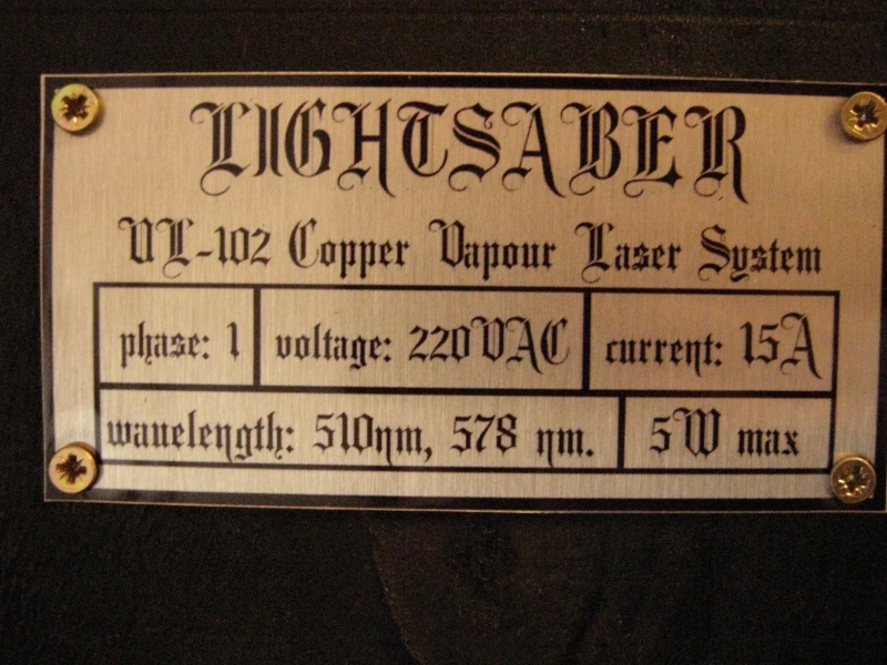
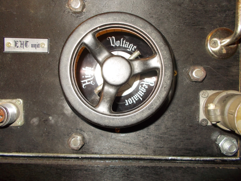
The desired result is achieved! It remains only a cosmetic design. First, I ordered the printing of stylish nameplates in English to designate all controls. At the same time, the name of the laser was born - Lightsaber. Because the power of the laser beam, its thickness, the characteristic sound effects that accompany the operation of the laser, very much resemble the light swords of the Jedi. And my, once child's dream of such a sword became satisfied, even in such a rather distorted form. Perhaps adherents of powerful laser pointers will disagree with me regarding the similarity with the lightsaber, but in my opinion, this laser has more similarities, despite the fact that waving it as a pointer will not work.

There is a video review of the resulting laser machine from my friend who came to visit.
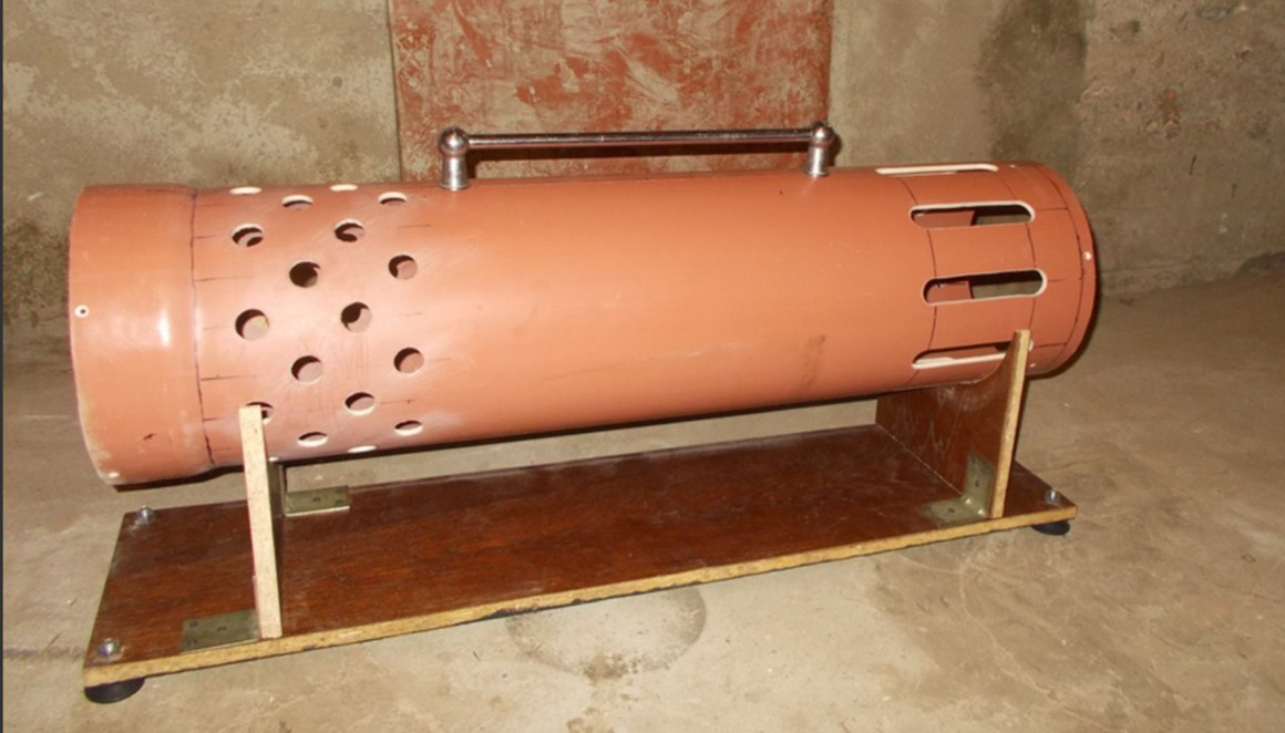
It remained to make the outer casing of the radiator and stand. Raw materials for it have already been prepared - a plastic sewer pipe with a diameter of 250 mm. It was cut to size, the bell was cut so that it was imperceptible, and air vents were drilled. The stand was also made of wood, specifically from the wall of the old cabinet. From above to the received case the beautiful handle for carrying was attached.

Then everything was painted and made additional false panels covering the case from the ends. The laser transmitter finally found its final form.
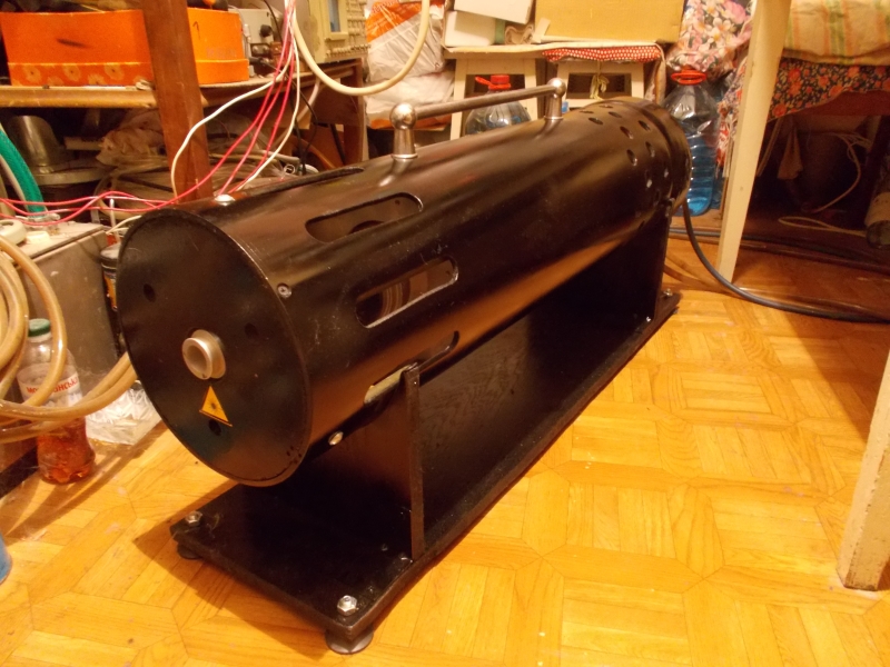
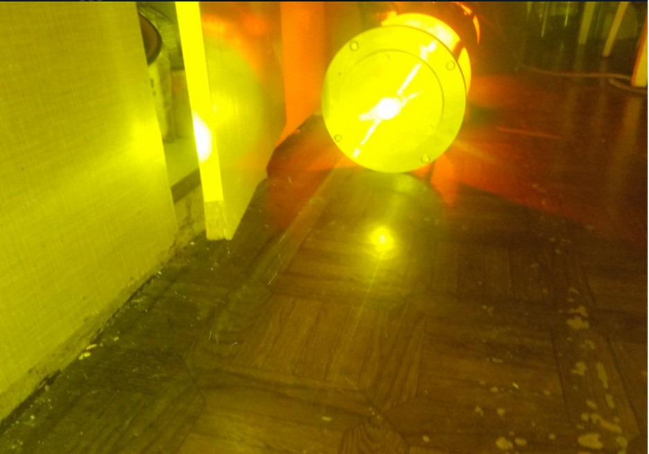
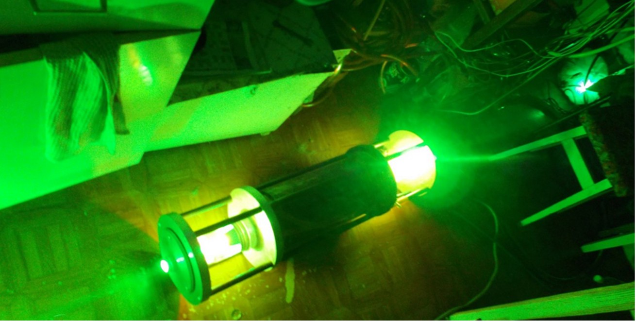
The ominous orange glow of the laser tube in the dark will not leave anyone indifferent. Especially when then it is replaced by a no less sinister green glow.

And the power source in its final form turned out to be two times the size of a conventional refrigerator, and with a total weight of not more than 100 kilograms. Which also benefits from the factory cabinet. And it fits well in the interior.
This is the story of a homemade laser machine, which brought me tremendous experience in laser technology, high-voltage pulse technology and other related disciplines. This project would not have been implemented without the support of my friends and acquaintances. Especially I would like to thank the people with the help of whom I managed to get 2 active elements of the UL-102, Pavel Gugin from the Institute of Physics and Technology of the Siberian Branch of the Russian Academy of Sciences, who helped with tips and references to the literature in optimizing the power part of the power source, Alex Neuromantix for helping to find scientific articles on the topic and a fruitful discussion, Alexandra “The Hedgehog” Larionov for having sold me additional tiratrons, and especially I want to thank the carrierand his friend, who helped with the delivery of these tiratrons from the Russian Federation, and finally, I would like to thank Denis “Neutron Storm” for the inspiration to do this project, for having once again been able to awaken the childhood dream. And also all those who followed the implementation of this project and provided moral support. Thank you all for reading. And for those who still have the question “Why was all this necessary,” read the disclaimer.
The main literary sources:
1. Grigor'yants A.G., Kazaryan M.A., Lyabin N.A. Copper vapor lasers: design characteristics and applications. Fizmatlit, 2005
2. Batenin V.M., Bokhan P.A., Buchanov V.V., Evtushenko G.S., Ghazaryan M.A., Karpukhin V.T., Klimovsky I.I., Malikov M. M. Lasers on self-limited transitions of metals. Fizmatlit, 2011
3. Lyabin N. А. Creation of modern industrial lasers and copper vapor laser systems for precision materials processing. Thesis for the degree of Doctor of Technical Sciences, Moscow, 2014
4. G. G. Petrash Lasers on metal vapors and their halides. Proceedings of LPI, vol. 181, 1987
PS: Almost immediately after the completion of the project, it was possible to catch an entirely new active element of a copper vapor laser, with an output power of 20 watts. GL201 "Crystal". But it will be a completely different story ...
Beginning in the first part .
summary of the first part :
- A power supply layout for the UL-102 copper vapor laser was built.
- The trial and error method found the conditions under which it was possible to obtain the generation of radiation
- Received tangible radiation power, about 1 W
- Assembled final version of the radiator
- Then followed a strange series of refusals, putting the project at risk of closure.
What happened next? Look under the cut.
Suspension of the project was due to the leakage of the active element of the UL-102. The active element was deposited in working condition, after 2 months it was found sticking. Judging by the steady-state gas pressure in it, the leakage was very slow, since it still could burn the streamer discharge of a characteristic form, but it was not ignited along the discharge channel. An attempt to find a leak was not successful. And all this despite the fact that the frame has already been assembled for this particular type of active element, and the installation of another type is impossible there.
This was how discharges in AE looked after it flowed.
There was no choice but to look for a new UL-102. I had to mobilize all my connections in various research institutes and laser laboratories in different cities, but it did bring a new result - a new active element was obtained, also a new one, in a factory box. At the same time he was more recent year of release.
Unpacking a new AE:
During the search for a new AE, I managed to get acquainted with a good specialist in the power supply system of the LML, who pointed out a number of my mistakes. The new AE was immediately installed in the finished emitter and the experiments were continued. The “direct excitation scheme” was returned again as the simplest, but with slight modifications of the grid circuit of the thyratron, which allowed increasing the stability of its operation to the level of the Blumlein generator, but still not enough. And again the epic failure - during long-term work at the rated power, the secondary winding of one of the power transformers IVN burned down, which was accompanied by the release of a huge cloud of yellow acrid smoke. As a temporary solution, these transformers were replaced by high-voltage transformers from the Soviet microwaves (also a legacy of my construction).
"A temporary solution to the transformer issue." The price for this was a reduction in the achievable anode voltage.
The burned-down transformer was disassembled in order to preserve its iron for winding a new one. This photo clearly shows the reason for overheating - good winding insulation. It was enough to exceed the current collection (which for Soviet transformers can be exceeded by 20-30%), as the winding is easily overheated. I have never met that the rest of the window in the gland (almost 1 cm on each side and 5 mm from the sides) was filled with epoxy ...
There remained one problem with the power source, which could not be overcome at this moment, namely, the poor stability of the operation of the thyratron in the operating mode region. Generation is still possible to get, but to maintain a long-term normal operation of the laser is already very difficult. A review of many articles in scientific journals made it possible to assert that the cause is the excess of the reverse voltage at the anode of the thyratron at the moment of its locking. The peculiarity of pulsed hydrogen thyratrons is that the maximum reverse voltage, for example, 25 kV for Тг700 \ 25 and Тги1000 \ 25, can be applied only 25 microseconds after the current through the thyratron stops, when all the plasma has already absorbed. It was quite logical to assume that this rule is not violated, since the ESR is 10 kHz, which means that the “gap” between pulses is 100 μs. But I did not take into account one factor. Plasma arc discharge inside a thyratron is inert. If not all, then many probably remember that if you look at the storyboard of the extinction of an arc lit on a large transformer substation, you can see that the arc does not disappear instantly, but over the course of several frames the video gradually splits into separate scraps, which then gradually fade away. The same thing happens in a pulsed hydrogen thyratron - after the current (locking) is stopped, the arc discharge also cools relatively slowly, breaking up into shreds, then disappears completely. Only after the end of this process can 25 kV reverse voltage be applied to it. If this is done earlier, then a new, unauthorized breakdown of the thyratron in the opposite direction will occur, and this will cause a fault of the IVN and the activation of its current protection. Or rather, not everything is so infernal. At the time of resorption of the discharge (before the expiration of the specified 25 µs post-pulse), the reverse voltage can be applied, and the thyratron will not break through. But only 5 kilovolts. Consequently, when a thyratron is operating in a copper vapor laser pumping scheme, this voltage is exceeded due to various non-stationary processes at the time of thyratron closure. Moreover, it becomes the greatest precisely when copper appears in the laser discharge, which greatly changes the characteristics of the AE as a load for the generator, which leads to a mismatch. when a thyratron is operating in a copper vapor laser pumping circuit, this voltage is exceeded due to various non-stationary processes at the moment of closure of the thyratron. Moreover, it becomes the greatest precisely when copper appears in the laser discharge, which greatly changes the characteristics of the AE as a load for the generator, which leads to a mismatch. when a thyratron is operating in a copper vapor laser pumping scheme, this voltage is exceeded due to various non-stationary processes at the moment of closure of the thyratron. Moreover, it becomes the greatest precisely when copper appears in the laser discharge, which greatly changes the characteristics of the AE as a load for the generator, which leads to a mismatch.
Many ways have been tried to eliminate this phenomenon by optimizing matching in different operating modes, but the radical result did not work - the conditions that gave stable operation on the mode of generation of radiation turned out to be unsuitable for heating mode and vice versa. The radical decision was only a change in the topology of the power unit, with the addition of new elements.
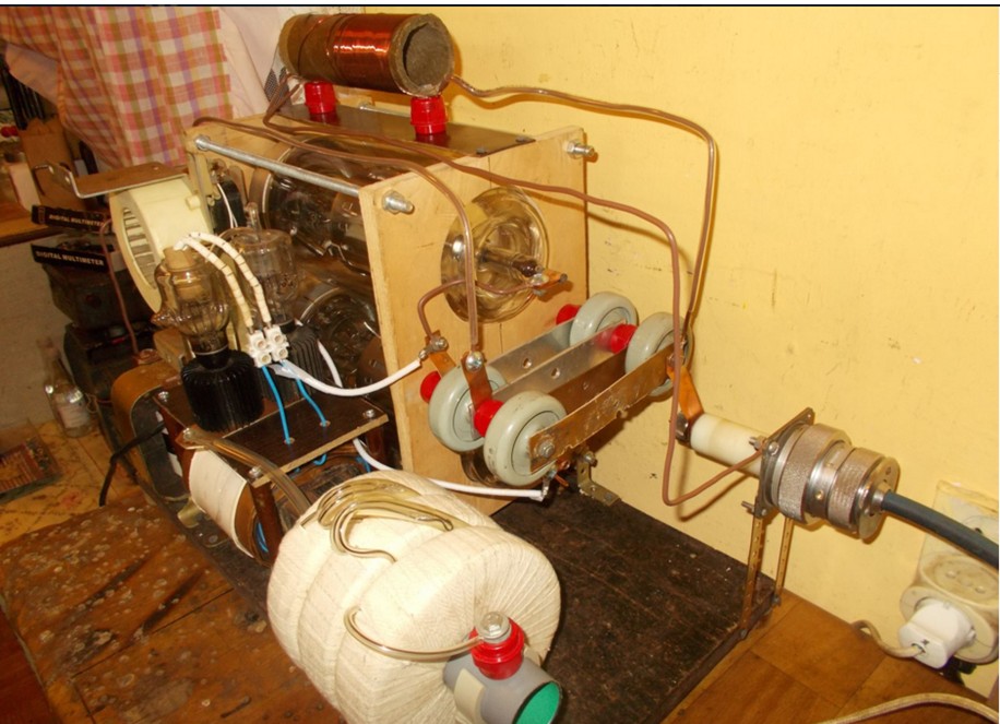
The circuit of the power unit was again converted to the seemingly promising scheme of the “controlled Arkadyev-Marx generator” on two thyratrons. This promised the use of again more simple and accessible TGI1-700 \ 25 thyratrons without an overload on the dissipated power at the anode. The generator of the control pulse was redone for this purpose in order to simultaneously unlock 2 thyratrons. The idea of the updated scheme was that there are 2 capacitors in it, which are in parallel at the moment of charge, and at the moment of unlocking the two thyratrons simultaneously, these capacitors are connected in series, as a result of which their voltages are added and applied to the AE electrodes. It also promised some improvement in the steepness of the pulse front on the AE and the resulting increase in the output radiation power, as the instantaneous voltage amplitude across the electrodes increased. A new layout of the power unit was assembled, which looked like this:
And on the diagram, it still looks pretty simple, although there are more details.
The tests showed the complete inoperability of the circuit in my performance - the thyratrons opened at odds with each other. Maybe I did something wrong. After that, I decided to change the topology of the power unit again, after consulting with a specialist. So, the modified Blumlein generator. It is almost identical to the usual Blumlein generator, but several more elements have been added to it. Namely, the so-called "chain of magnetic compression of the pulse." The essence of her work is that the amplitude of the flowing pulsed current through the saturable choke at the time of saturation of the choke increases sharply. Since the amount of energy transferred by one pulse is limited, and the initial pulse duration is also limited, then at the moment of saturation of the inductor and the increase of the current in the circuit - this portion of energy is nothing but to “shrink” in time, accordingly, the current pulse on the AE (laser tube) is significantly reduced. And if so, then the duration of the current pulse passing through the thyratron can be increased, and the duration of the pulse on the laser tube can be reduced, and most importantly, the front slope of the AE can be increased and the output radiation power can be raised. It looks very tempting.
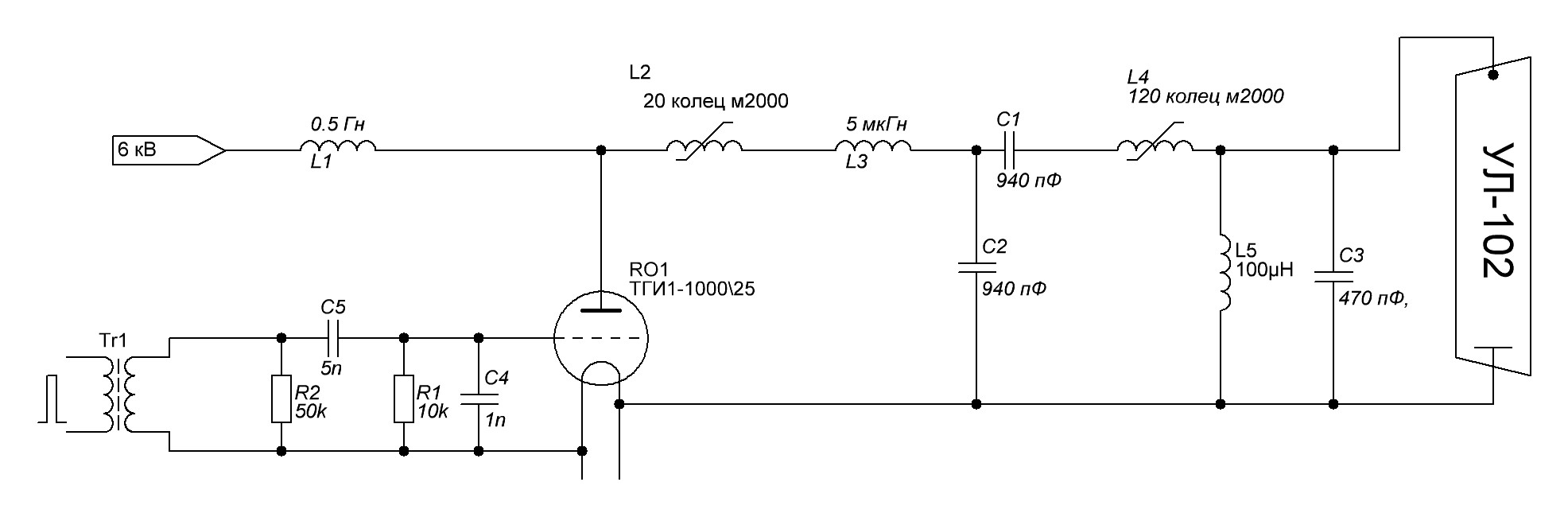
This is how the diagram I assembled with the given par values.
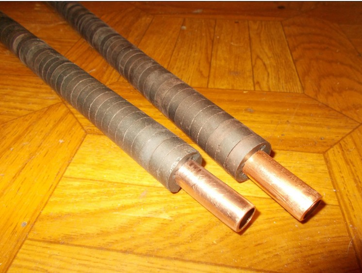
The L2 choke stretches the current pulse through the thyratron in time, and the L4 choke is the saturable choke for the “magnetic compression” of the pulse on the laser tube. And this scheme finally began to work stably! The result definitely justified the effort expended on manufacturing the nonlinear throttle. I’ll stop here a little more. Again, I decided to repeat the construct described in the literature. And there it was proposed to make a choke consisting of one “coil” of a thick copper tube passed through 120 small ferrite ringlets. A piece of copper pipe with a diameter of 12mm was purchased in a store for refrigerators. Were bought ferrite rings with a small margin. The matter remained for small - to string them on the tube. Stringing them all in one time was irrational - it turned out too long sausage. Then I decided to make two pieces of tube, string them on 60 rings and fold U-shaped. Easier said than done. The fact is that the tube is not ideally smooth, and in the rings the diameter is slightly, in tenths of a millimeter, but it is different. There were even rings in which the hole was tapered or elliptical. And one and the other at the same time.
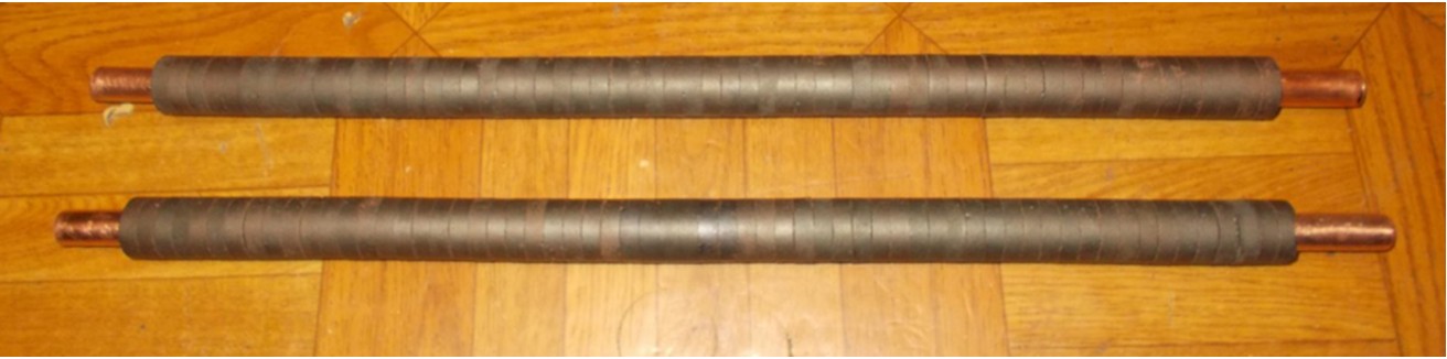
Attempting to pull the ring by force led to its instant splitting into pieces. About half put on freely, without problems. Then I had to process the copper tube with the sandpaper, until the next rings started to climb. Then again skin, put on again ... And so repeat until the bitter end. The result was such a construction.
It was installed in the new layout of the power unit.
Installation is running. The laser warms up. For half an hour, no protection operation. This is a success! Finally, spontaneous emission of copper appears, followed by weak generation. Then the tuning of the mirrors of the resonator. And the room is illuminated by a powerful laser beam of poisonous green color!
The light spot on the white tiled wall is so bright that the whole room is brightly lit. And while the brightness of the glow continued to increase, until it reached a constant value. As the brightness increased, the color of the beam from poisonous green to green lemon changed, which indicated the effective generation of the yellow line. The radiation power exceeded the previously obtained at least several times, the lower limit was assumed to be not less than 3 watts. With a power consumption of 1800 watts.
The beam transmitted through the lens is already very vigorously burning on the cardboard.
Tests of the laser are on video:
The laser beam is clearly visible. Its diameter corresponds to the diameter of the discharge channel, 20 mm.
The discharge channel inside the AE at the operating temperature is almost white hot.
The laser beam is clearly visible in a lit room.
Behind the short-focus lens, the cone is beautifully visible, first converging before the focus of the beam, then diverging (area of the waist) of the rays. Combustible items in the focus is better not to put.
With the help of a fragment of a CD-ROM, you can expand the beam into a spectrum. It clearly shows that the beam has green and yellow lines, while the yellow has become much more powerful than before.
The yellow line can be identified separately by a filter that blocks the green light, namely, orange.
Now you could exhale and begin the transition from the layout to the finished product. The first in the case was packed power unit. Wood and plywood were chosen as materials for the hull, such as those that are most easily handled using a home electric tool. All elements were placed on a compact base, the magnetic compression choke was hidden in a section of sewer pipe and blown through by a fan. The anode of the thyratron is blown by its fan. And so that the hot air does not accumulate in a closed case, the third most powerful fan is installed, creating a draft inside the unit. During the installation of the components, it looked like this.
And in the collection - like this.
Next was a control generator packed for a power thyratron grid. The master oscillator and amplifier moved to a common body, made so that its width and depth were equal to the width and depth of the power unit.
Began to get something like a dashboard. The IVN unit was, in general, already ready, it took only side walls to be added. At the same time, the exterior decoration of the blocks continued - it was decided to paint them black.
Ready stand turned out so.
And yet I was haunted by the feeling that the work of the laser could still be improved, even more radiation power could be increased. Since inside the IVN, there still remained “temporary” transformers from microwaves, which did not allow obtaining an output voltage of more than 5 kV after the rectifier. It was a volitional decision - to make a completely new high-voltage transformer with oil insulation and water-cooled. The task was set: output alternating voltage 7 kV, continuous output current - 400 mA. From the secondary winding decided to make taps every 500V, starting with a voltage of 4.5 kV. Calculations showed that it is possible to use a core from a burned-out transformer, while the window was completely filled. First, I wound the transformer itself.
Then he was strengthened to the textolite plate, through which all the conclusions came out.
Then a tank was made of the sheet iron found at the acceptance of scrap.
Inside is a coil for cooling the oil.
Then the transformer was assembled.
And installed on his place.
Launching a laser with a new transformer made it possible to increase the power to about 5 watts! Those. It turned out to be the full equivalent of the factory setting mentioned at the beginning of the article. Only smaller dimensions, weight and with less energy consumption.
At full power, the color of the beam becomes more yellow.
The desired result is achieved! It remains only a cosmetic design. First, I ordered the printing of stylish nameplates in English to designate all controls. At the same time, the name of the laser was born - Lightsaber. Because the power of the laser beam, its thickness, the characteristic sound effects that accompany the operation of the laser, very much resemble the light swords of the Jedi. And my, once child's dream of such a sword became satisfied, even in such a rather distorted form. Perhaps adherents of powerful laser pointers will disagree with me regarding the similarity with the lightsaber, but in my opinion, this laser has more similarities, despite the fact that waving it as a pointer will not work.
There is a video review of the resulting laser machine from my friend who came to visit.
It remained to make the outer casing of the radiator and stand. Raw materials for it have already been prepared - a plastic sewer pipe with a diameter of 250 mm. It was cut to size, the bell was cut so that it was imperceptible, and air vents were drilled. The stand was also made of wood, specifically from the wall of the old cabinet. From above to the received case the beautiful handle for carrying was attached.
Then everything was painted and made additional false panels covering the case from the ends. The laser transmitter finally found its final form.
The ominous orange glow of the laser tube in the dark will not leave anyone indifferent. Especially when then it is replaced by a no less sinister green glow.
And the power source in its final form turned out to be two times the size of a conventional refrigerator, and with a total weight of not more than 100 kilograms. Which also benefits from the factory cabinet. And it fits well in the interior.
This is the story of a homemade laser machine, which brought me tremendous experience in laser technology, high-voltage pulse technology and other related disciplines. This project would not have been implemented without the support of my friends and acquaintances. Especially I would like to thank the people with the help of whom I managed to get 2 active elements of the UL-102, Pavel Gugin from the Institute of Physics and Technology of the Siberian Branch of the Russian Academy of Sciences, who helped with tips and references to the literature in optimizing the power part of the power source, Alex Neuromantix for helping to find scientific articles on the topic and a fruitful discussion, Alexandra “The Hedgehog” Larionov for having sold me additional tiratrons, and especially I want to thank the carrierand his friend, who helped with the delivery of these tiratrons from the Russian Federation, and finally, I would like to thank Denis “Neutron Storm” for the inspiration to do this project, for having once again been able to awaken the childhood dream. And also all those who followed the implementation of this project and provided moral support. Thank you all for reading. And for those who still have the question “Why was all this necessary,” read the disclaimer.
The main literary sources:
1. Grigor'yants A.G., Kazaryan M.A., Lyabin N.A. Copper vapor lasers: design characteristics and applications. Fizmatlit, 2005
2. Batenin V.M., Bokhan P.A., Buchanov V.V., Evtushenko G.S., Ghazaryan M.A., Karpukhin V.T., Klimovsky I.I., Malikov M. M. Lasers on self-limited transitions of metals. Fizmatlit, 2011
3. Lyabin N. А. Creation of modern industrial lasers and copper vapor laser systems for precision materials processing. Thesis for the degree of Doctor of Technical Sciences, Moscow, 2014
4. G. G. Petrash Lasers on metal vapors and their halides. Proceedings of LPI, vol. 181, 1987
PS: Almost immediately after the completion of the project, it was possible to catch an entirely new active element of a copper vapor laser, with an output power of 20 watts. GL201 "Crystal". But it will be a completely different story ...
Beginning in the first part .