Using Intel RealSense Camera with TouchDesigner. Part 1
- Transfer

TouchDesigner Company Derivative - a popular platform and software used around the world to create interactive solutions and real-time animation in the presentations, as well as to display the three-dimensional animation, maps and charts, as well as more recently in virtual reality systems. With camera support, Intel RealSense TouchDesigner is becoming an even more versatile and powerful tool. It should be noted the ability to import objects and animations from other 3D packages into TouchDesigner using .fbx files, as well as the ability to work with already rendered animation clips and images.
In this two-part article, I’ll talk about integrating the Intel RealSense camera into TouchDesigner and how to use it. The demos in the first part use an Intel RealSense camera with TOP nodes. The demos in the second part use the CHOP nodes. The second part also explains the creation of virtual reality sequences and semicircular panoramas using the Intel RealSense camera.
Both parts include animations and downloadable TouchDesigner * (.toe) files that you can use to view. To receive TouchDesigner * (.toe) files, click here . In addition, a free copy of TouchDesigner * is available for non-commercial use.. It is fully functional (except that the maximum resolution is limited to 1280 by 1280).
Note. There are currently two types of Intel RealSense cameras: the F200 short -range camera and the R200 long-range camera . Due to its ultra-compact size, the R200 is very convenient for performances and other use cases when the camera should be hidden. Unlike the larger F200, the R200 does not support tracking of hands and fingers, as well as tracking of markers. TouchDesigner * supports both Intel RealSense camera models: both the F200 and R200.
I quote from a web page TouchDesigner: “TouchDesigner * is a revolutionary software platform that enables artists and designers to work with materials in an open, free environment. TouchDesigner * is the ideal solution for interactive multimedia projects using video, sound, 3D graphics, input using controllers, the Internet and databases, DMX light sources, environmental sensors, and in general everything you can imagine. This is a powerful environment for mixing all of these elements in an infinite number of ways. "
I asked Malcolm Bechard, senior developer of Derivative, to comment on using Intel RealSense camera with TouchDesigner *:
“Thanks to the node-based TouchDesigner * procedural architecture, Intel RealSense camera data can be instantly retrieved, visualized, then transferred to other nodes without wasting time writing code. You can quickly prototype ideas and develop with instant feedback. The camera is represented by a node in TouchDesigner *, which means that there is no need to close and recompile the application at each development iteration. The Intel RealSense camera extends the capabilities of TouchDesigner *, providing users with a significant number of off-the-shelf modules, such as gestures, hand tracking, face tracking, depth data. All this can be used for interaction. There is no need to use a low-level analysis of hand position data to recognize gestures: this has already been done. ”
Using Intel RealSense Camera in TouchDesigner
TouchDesigner * is a node-based program and platform that uses Python * as its primary scripting language. There are five categories of nodes that perform different operations and have different functions: TOP nodes (textures), SOP (geometry), CHOP (animation and sound), DAT (tables and text), COMP (three-dimensional geometric nodes, and nodes for creating two-dimensional control panels) and MAT (materials). TouchDesigner * programmers, in consultation with Intel developers, created two specific nodes, the Intel RealSense TOP camera node and the Intel RealSense CHOP camera node to integrate the Intel RealSense camera into the program.
Note.This article is intended for users who are already familiar with TouchDesigner * and its interface. If you do not have experience with TouchDesigner * and you are going to gradually understand this article, I recommend that you first review the documentation available here .
Note. When using an Intel RealSense camera, range should be considered for optimal results. On this Intel web page, the range of all camera models is indicated and recommendations on the use of cameras are given.
Intel RealSense TOP Camera Node
The TOP nodes in TouchDesigner * perform many of the operations typically found in image composition programs. The Intel RealSense TOP camera node complements these features with 2D and 3D data from the Intel RealSense camera. The Intel RealSense TOP camera node contains a number of settings for receiving different types of data.
- Color. Video from the Intel RealSense camera color sensor.
- Depth. The calculated depth of each pixel. 0 means that the pixel is at a distance of 0 meters from the camera, 1 means that the pixel is at the maximum possible distance or further.
- Raw depth. Values are taken directly from the Intel RealSense SDK. Again, 0 means 1 meter from the camera, 1 means that the pixel is at the maximum possible distance or further.
- Наглядная глубина. Изображение Intel RealSense SDK в оттенках серого, позволяющее наглядно представить глубину. Его невозможно использовать для фактического вычисления точного расстояния каждого пикселя до камеры.
- Отображение глубины на цветной UV-карте. Значения UV из 32-разрядной плавающей текстуры RG (обратите внимание, что в ней только два цвета (красный и зеленый), а синего цвета нет), необходимые для выравнивания изображения глубины в соответствии с цветным изображением. Для выравнивания изображений можно использовать узел TOP Remap.
- Display color on UV depth map. UV values from a 32-bit floating RG texture (note that it has only two colors (red and green) and no blue) are needed to align the color image with the depth image. To align the images, you can use the TOP Remap node.
- Infrared image. Raw video of the infrared sensor of the Intel RealSense camera.
- Point cloud. This is literally a cloud of points in three-dimensional space (with X, Y, Z coordinates) or data points created by the Intel RealSense camera scanner.
- UV color map of point clouds. Can be used to get the color of each point from the color image stream.
Note. You can download this RealSensePointCloudForArticle.toe file to use as a simple initial template for creating 3D animated geometry from Intel RealSense camera data. This file can be modified in many ways. Together, the top three nodes of the Intel RealSense camera - Point Cloud, Color and Point Cloud Color UV - allow you to create three-dimensional geometry from points (particles) with a color image overlay. This opens up many interesting possibilities.

Geometry of a point cloud. This is an animated geometry created using an Intel RealSense camera. It is very good to use when speaking in public. You can add the sound of a talking animated character. TouchDesigner * can also use audio data to create real-time animations.
Intel RealSense Camera CHOP Node
Note. There is another Intel RealSense camera CHOP node responsible for 3D tracking data and positioning. We will discuss it in the second part of this article.
Demo 1. Using the Intel RealSense TOP Camera Node
For the first TOP demo, click the button at the top of the article: settingUpRealNode2b_FINAL.toe.
Demo 1, Part 1. You will learn how to configure the Intel RealSense TOP camera node and connect it to other TOP nodes.
1. Open the Add Operator / OP Create dialog box .
2. In the TOP section, click RealSense .
3. On the Setup page of the Intel RealSense TOP camera node, for the Image parameter, select Color from the drop-down menu. The Intel RealSense TOP camera node displays an image of what the camera is aimed at, as when using a conventional video camera.
4. Set the resolution of 1920 by 1080 for the Intel RealSense camera.

Configuring the Intel RealSense TOP node is easy.
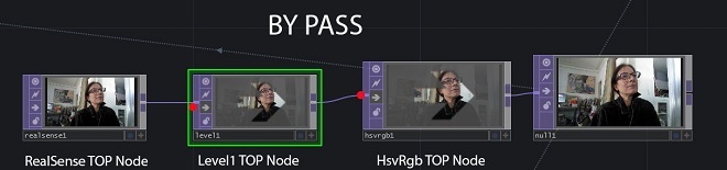
5. Create a Level TOP node and connect it to the Intel RealSense TOP camera node.
6. On the Pre parameters page of the Level TOP node, select Invert and move the slider to 1.
7. Connect the Level TOP node to the HSV To RGB TOP node, then connect the latter to the Null TOP node.

The Intel RealSense TOP camera node can be connected to other TOP nodes to obtain the desired image and create the desired effects.
Then we will transfer the created image to the Phong MAT node (material) so that it can be superimposed on various geometric shapes as a texture.
Using Intel RealSense Camera Data to Create Textures for Geometry
Demo 1, Part 2. This exercise shows how to use the Intel RealSense TOP camera node to create textures and how to add them to the MAT node so that you can assign their geometry in the project.
1. Add a Geometry COMP node to the scene.
2. Add the Phong MAT node.
3. Take the Null TOP node and drag it onto the Color Map parameter of the Phong MAT node.

The Phong MAT node uses Intel RealSense camera data for its Color Map parameter.
4. On the Render parameters page of the Geo COMP node, add the phong1 type to the Material parameter to use the phong1 node as the material.

The Phong MAT node uses Intel RealSense camera data for its Color Map parameter added to the Render / Material parameter of the Geo COMP node.
Creating a Box SOP node and texturing with the newly created Phong shader
Demonstration 1, part 3. You will learn how to assign the Phong MAT shader, just created using data from the Intel RealSense camera, to the Geometry SOP node of the cube.
1. Go to node geo1 to its child level ( / project1 / geo1 ).
2. Create a Box SOP node, a Texture SOP node, and a Material SOP node.
3. Remove the Torus SOP node that was there, then connect the box1 node to the texture1 and material1 nodes.
4. In the Material parameter of the material1 node, enter ../phong1. This is the phong1 MAT node created at the parent level.
5. To place the texture on each side of the cube, in the Texture / Texture Type parameters of the texture1 node, place face and set the Texture / Offset put parameter to .5 .5 .5.
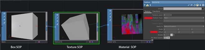
At the child level of the geo1 COMP node, the Box SOP, Texture SOP, and the Material SOP nodes will be connected. The Material SOP node now gets the texture from the phong1 MAT node at the parent level (... / phong1).
Animating and instantiating Box node geometry
Demo 1, Part 4. You will learn how to rotate a Geometry SOP node using the Transform SOP node and a simple expression. You will then learn how to instantiate the geometry of a Box node. As a result, we get a screen with many rotating cubes, each of which will have textures from the Intel RealSense TOP camera node.
1. To animate the rotation of the cube around the X axis, insert the Transform SOP node after the Texture SOP node.
2. Place the expression in the X component (first field) of the Rotate parameter in the transform1 node of the SOP. This expression does not depend on frames; it will continue to work and will not begin to repeat at the end of frames on the timeline. I multiplied the value by 10 to increase the speed: absTime.seconds * 10

Here you can see that the cube is spinning.
3. To create cubes, go to the parent level (/ project1) and on the Instance parameters page of the geo1 COMP node, set Instancing to On.
4. Add a Grid SOP node and a SOP – DAT node.
5. Set the grid parameters: 10 rows and 10 columns, size - 20 and 20.
6. In the SOP – DAT node parameters for SOP, set grid1 and make sure that the Extract parameter is set to Points.
7. On the Instance parameters page of the geo1 COMP node, enter the Instance CHOP / DAT parameter: sopto1.
8. Complete the TX, TY, and TZ parameters using P (0), P (1), and P (2), respectively, to indicate which columns from the sopto1 node to use for instance positions.

9. If you want the image from the Intel RealSense camera to be transmitted without filtering, disable the Level TOP and HSV to RGB TOP nodes or bypass these nodes.
Real-time rendering and animation
Demonstration 1, part 5. You will learn how to set up a scene for rendering and display the image in direct display mode or as a video file.
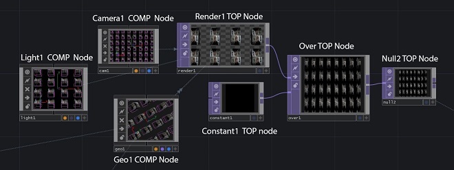
1. To render the project, add the nodes Camera COMP, Light COMP, and Render TOP. By default, the camera renders all the geometry components in the scene.
2. Move the camera back about 20 units along the Z axis. For lighting, leave the default values.
3. Set the rendering resolution to 1920 by 1080. By default, the rendering background is transparent (alpha value is 0).
4. To make the background opaque black, add the Constant TOP node and change the value of the Color parameter to 0,0,0 to set the color to black by specifying the Alpha parametervalue 1. You can select any other color.
5. Add the Over TOP node and connect the Render TOP node to the first connection, and the Constant TOP node to the second. In this case, the background pixels will receive the value (0, 0, 0, 1), that is, they will cease to be transparent.
Another way to change the TOP transparency value to 1 is to use the Reorder TOP node and set its Output Alpha parameter to Input 1 and One.
Displays a scene with an opaque black background.

A full screen with textured rotating cubes is visible here.
If you prefer to output the animation to a file instead of playing it in real time during the demonstration, you need to select the Export movie dialog box in the file sectionon the top panel of TouchDesigner. In the TOP Video node parameter, enter null2 for this particular example. Otherwise, enter any TOP node that needs rendering.

Here is the Export Movie panel with the null2 node. If there was also a CHOP audio node, then I would place CHOP Audio immediately below null2.
Demonstration 1, part 6. One of the useful features of the TouchDesigner * platform is the ability to create animations in real time. This feature is especially useful when using the Intel RealSense camera.
1. Add the Window COMP node, and in the operator parameter, enter the null2 TOP node.
2. Set the resolution to 1920 by 1080.
3. Select the desired monitor in the Location parameter. The Window COMP node allows you to display all the animation in real time on the selected monitor. Using the Window COMP node, you can specify the monitor or projector to display the image on.

You can create any number of Window COMP nodes to display the image on other monitors.

Demo 2. Using Intel RealSense TOP Camera Node Depth Data
The Intel RealSense TOP camera node contains a number of other settings for creating textures and animations.
In Demo 2, we use depth data to apply blur to an image based on depth data received from the camera. In the archive we will use the file RealSenseDepthBlur.toe .
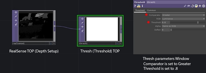
First create an Intel RealSense TOP camera node and set the Image parameter to Depth . The depth image contains pixels with a value of 0 (black) if they are close to the camera, and with a value of 1 (white) if they are far from the camera. The range of pixel values is determined by the Max Depth parameter., its value is indicated in meters. By default, this parameter is set to 5. This means that pixels located 5 meters from the camera (or further) will be white. Pixels with a value of 0.5 are at a distance of 2.5 m from the camera. Depending on the actual distance between the camera and you, it makes sense to change this value to a smaller one. In this example, we changed the value of this parameter by 1.5 m.
Then we need to process the depth to remove objects that are outside the range of interest to us. To do this, we use the Threshold TOP node.
1. Create a Threshold TOP node and connect it to the realsense1 node. You need to remove all pixels beyond a certain distance from the camera, so set the Comparator to Greater, and toThreshold - value 0.8. In this case, pixels with a value greater than 0.8 (which corresponds to a distance of 1.2 m or more, if the Max Depth parameter in the Intel RealSense TOP camera node is set to 1.5) will be 0, and all other pixels will be 1.
2 Create a Multiply TOP node, connect the realsense1 node to the first input, and the thresh1 node to the second input. When you multiply pixels by 1, they will remain unchanged, and when you multiply other pixels by 0, they will be reset to zero. Now the multiply1 node contains only pixels greater than 0 for that part of the image on which you want to blur, which we will do now.
3. Create a Movie File node in TOP and select a new image for the File parameter. In this example, we select Metter2.jpg from the TouchDesigner * Samples / Map folder.
4. Create a Luma Blur TOP node and connect moviefilein1 to the first input of lumablur1, and multiply1 to the second input of lumablur1.
5. In the lumablur1 parameters, set the White Value parameter to 0.4, the Black Filter Width parameter to 20, and the White Filter Width parameter to 1. Due to this, pixels with the value of the first input 0 will have a blur filter width of 20, and pixels with value of 0.4 or more - blur width 1.

Everything as a whole.
As a result, we get an image where the pixels on which the user is located are not blurred, and all other pixels are blurred.
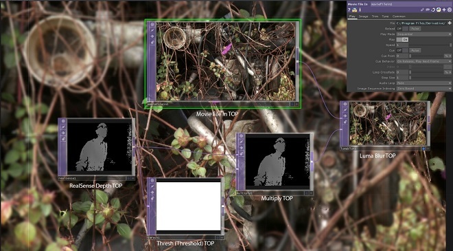
The background displayed by the Luma Blur TOP display shows how blurry the image is.
Demo 3: Using Intel RealSense TOP Camera Node Depth Data with Remap TOP Node
In the archive we will use the RealSenseRemap.toe file .
Note. The cameras of the depth and color of the Intel RealSense TOP cameras node are physically located in different places, therefore, the images that they produce do not coincide with each other by default. For example, if your hand is exactly in the middle of the color image, then it will not be in the middle of the depth image, but will be slightly shifted left or right. Offsetting the UV card eliminates this problem by aligning and superimposing pixels. Note the difference between aligned and unaligned TOP nodes.

Remap TOP combines the depth data received from the Intel RealSense TOP camera node with the color data received from the same node using the UV data for combining depth with color in the same space.
Demo 4. Using a point cloud in the Intel RealSense TOP camera node
In the archive we will use the PointCloudLimitEx.toe file .
In this exercise, you will learn how to create animated geometry using a point cloud, the Intel RealSense TOP camera node, and the Limit SOP node. Note that this approach is different from the Point Cloud file example at the beginning of this article. The previous example uses GLSL shaders, which makes it possible to create much more points, but this task is complicated and goes beyond the scope of the article.
1. Create a RealSense TOP node and set the Image parameter to Point Cloud.
2. Create a TOP – CHOP node and connect it to the Select CHOP node.
3. Connect the Select CHOP node to the Math CHOP node.
4. In the TOP parameter of the CHOP topto1 node, enter: realsense1.
5. In the Channel Names parameters of the Select CHOP node, enter rgb, separating the letters with spaces.
6. In the CHOP node math1 in the Multiply parameter value field, enter: 4.2.
7. On the Range parameters page, in the To Range parameter value field, enter: 1 and 7.
8. Create a Limit SOP node.
To quote a wiki page at www.derivative.ca : “Limit SOP creates geometry from the data transmitted by the CHOP nodes . It creates geometry at each sample point. Using the Output Type parameter on the Channels page, you can create different types of geometry. ”
1. On the page with parameter limit1 CHOP Channelsenter r for the X Channel parameter, “g” for the Y Channel parameter and “b” for the Z Channel parameter.
Note. Moving the r, g, and b values to other channels X, Y, and Z changes the geometry being formed. Therefore, you can try the following later: On the Output parameters page, for the Output Type parameter, select Sphere at Each Point from the drop-down list. Create a SOP – DAT node. On the parameters page for SOP, enter limit1 or drag the node limit1 CHOP into this parameter. Leave the default value for Points in the Extract parameter. Create the Render TOP, Camera COMP, and Light COMP nodes. Create a Reorder TOP node, set the Output Alpha to Input 1 and One, connect it to the Render TOP node.

When you change the image from the Intel RealSense camera, the geometry also changes. This is the final project.

Final images in Over TOP CHOP node. By changing the order of the channels in the Limit TOP parameters, you change the geometry based on a point cloud.
In the second part of this article, we will discuss the Intel RealSense CHOP camera node and creating content for recording and demonstrating in real time, demonstrating hemispherical panoramas and virtual reality systems. In addition, we will discuss the use of the Oculus Rift CHOP node. We’ll talk about hand tracking, face and marker tracking.