March 23, 2016 at 17:23
About measuring the flow rate of liquids and gases
This year, we began to represent IST in Russia, a Swiss manufacturer of thin-film sensors for temperature, relative humidity, fluid conductivity and flow rate.
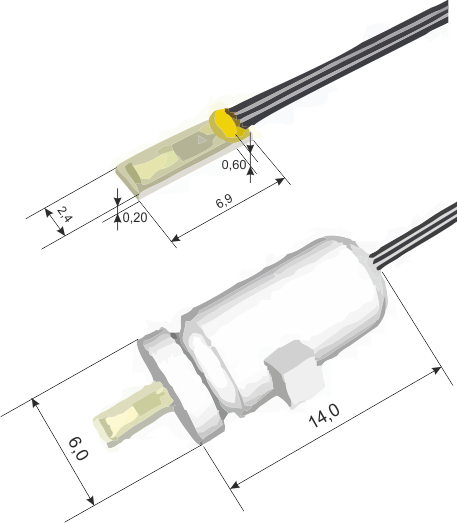 IST products are not a mass market; they do not produce
 analogues of DHT22 with millions of copies of cheap chips for standard applications. Instead, the emphasis is on special tasks: non-standard designs and temperature ranges, increased accuracy, minimum response time, and so on.
Among the diverse IST products there is such an interesting thing as flow sensors - flow rate sensors for continuous media. Under the cat I tell you how they work, how they look and why they are needed. I think that it will be interesting not only to flowmeter developers.
So, various physical effects are used to measure the flow of liquids or gases. To measure the flow velocity, mechanical, optical, electromagnetic, ultrasonic and other sensitive elements are used, which make it possible by indirect characteristics to determine the flow rate of a continuous medium passing through a pipe.
Since most of the IST products are platinum temperature sensors (thermal resistance), thermal effects are also used to determine the flow rate.
In heat flow meters, measurements are made either by cooling a heated body placed in the flow (hot-wire anemometers) or by transferring heat energy between two points located along the flow (calorimetric flow meters). Let's see how both principles are used in real applications.
Flowmeters with IST hot-wire anemometers are mainly used for gas flows. In the simplest case, they consist of a heating element and a temperature sensor. In fact, these are two thermal resistances, on the basis of which the following algorithm is implemented:
In the absence of a flow, the temperature of the microheater remains unchanged, and in the presence of a flow, the heater begins to give off heat to the external environment. The amount of heat that is given to the flow depends on several factors: on the initial temperature difference of the heater and the medium, on the parameters of the pipe and on the actual flow rate.
Since the temperature difference is determined by the switching circuit of the flow sensor, and we consider the parameters of the pipe unchanged, the heat transfer of the heating element can be used to measure the flow rate.

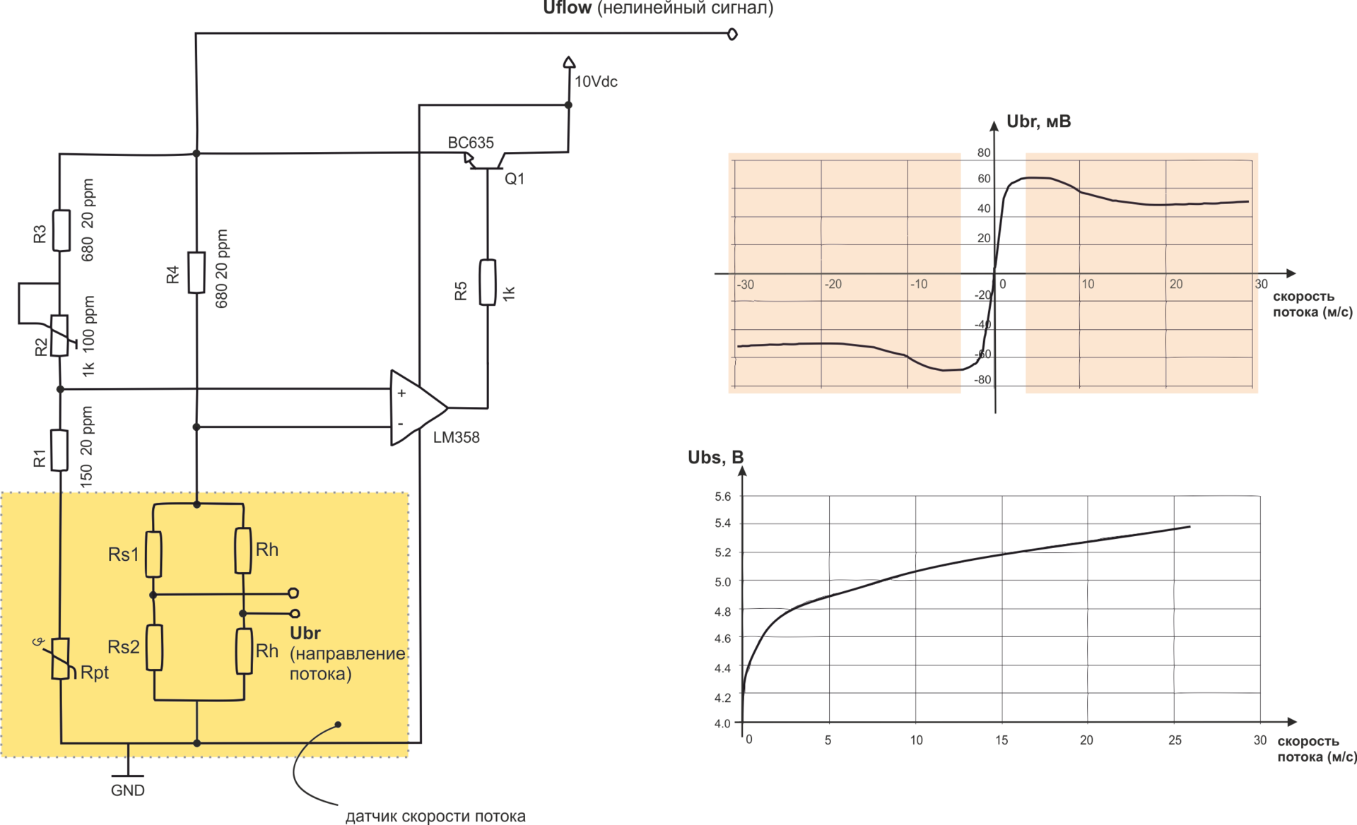
The heater and temperature sensor are included in the bridge circuit, which is balanced in the absence of flow and unbalanced when the resistance of the heater changes. As the flow rate increases, the heater cools, the bridge is unbalanced, and the unbalance signal is fed to the amplifier. The output of the amplifier tells the heater a higher temperature and brings the bridge back to equilibrium. The same signal is used as an output, i.e. as a function of flow rate.
With the known parameters of the pipe, the position of the sensor, the type of flow, as well as the constant thermophysical characteristics of the gas (composition, pressure, temperature), such a function can be calculated using one of the well-known methods.
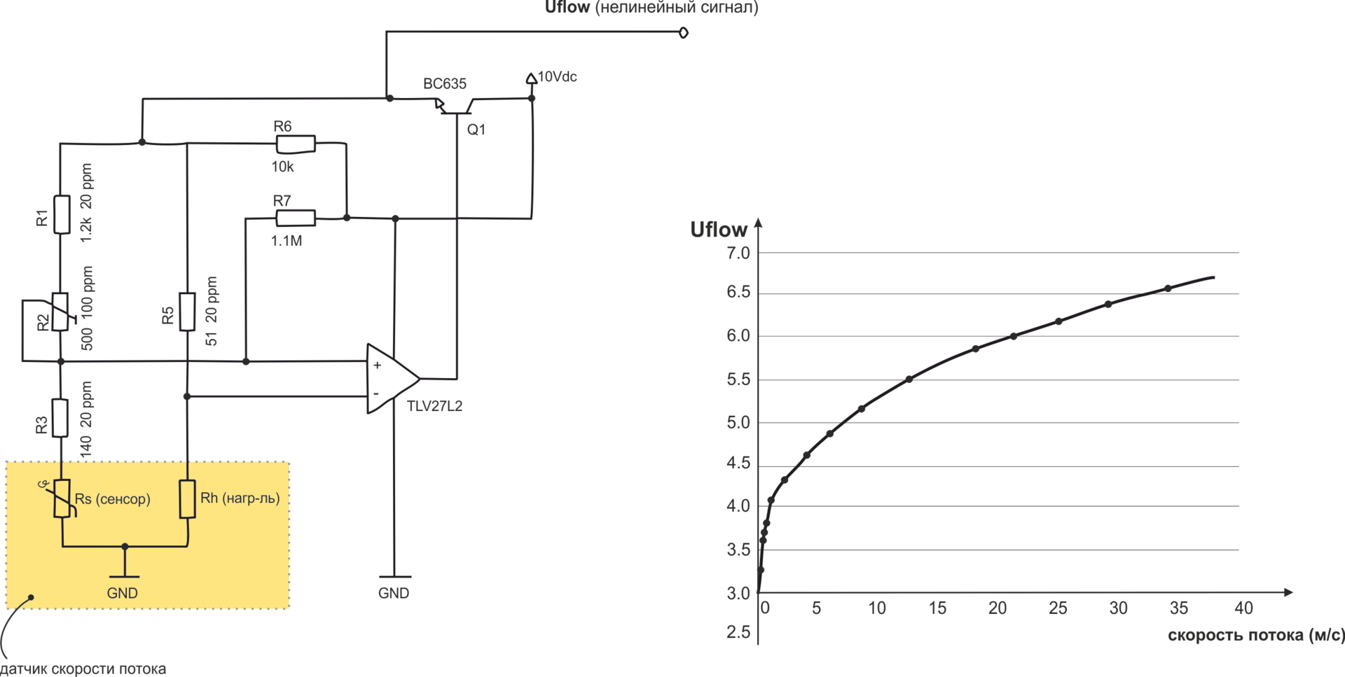
The illustration is an example.flow sensor connection diagrams and a graph of the dependence of the Uflow voltage on the flow rate.
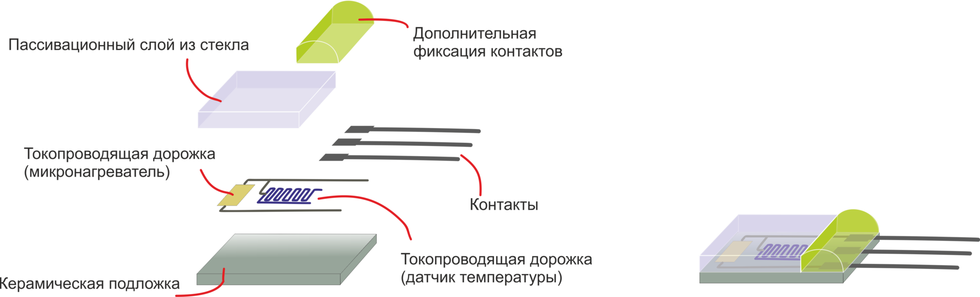
Sensors of the FS7 series work by this principle. Conducting paths are applied on a ceramic zirconia substrate - a platinum micro-heater and a temperature sensor, between which connections are provided. The whole structure is covered with a thin insulating layer of glass.
Sensitive elements of this design allow you to measure the flow velocity in the range from 0 to 100 m / s with a sensitivity of 0.01 m / s and an error of less than 3% of the measured value. However, the accuracy of measurements is determined not only by the sensitive element, but also by the circuit of its inclusion, and by the method of calibration of the final device.
The operating temperature range of the FS7 sensor is -20 ... 150 ° C for standard execution, however, IST practices the manufacture of sensors with a permissible temperature up to +400 ° C.
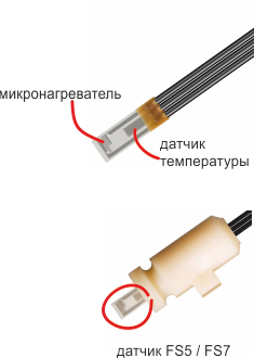
The figure shows two versions of the FS7 sensors - in the case and without it.
It is important to note that the FS7 sensors, as well as the FS2 discussed below, are used mainly for gases, as well as for liquid media that do not contain water - during prolonged operation in water, the upper insulating layer of the sensor gradually breaks down and electrolysis occurs.
For the flow of water and other similar media, an Out Of Liquid module is provided - an anemometric sensor, the elements of which are isolated from the stream. Out Of Liquid is a small stainless steel tube with a micro heater and a temperature sensor on its outer wall.
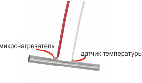
The tube has a length of 40 mm and a diameter of 4 mm, the working temperature range of this solution is from -50 ° C to +180 ° C.
Hot-wire anemometers have some obvious limitations. In particular, they do not allow determining the direction of flow and are not suitable for applications requiring high sensitivity of the sensor.
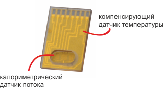
Calorimetric flow meters, in contrast, are designed for relatively slow gas flows with a variable direction. The calorimetric sensor consists of three elements - a microheater and two sensors that measure the temperature before and after it. In the absence of flow, the heat spot emitted by the heater is stationary, therefore, the continuous medium at the right and left of the heater has the same temperature. When a flow occurs, the heat spot “shifts” according to the direction and speed of the flow. Thus, with known pipe parameters and medium characteristics, the flow rate can be measured by the difference in temperature sensor readings.

In the manufacture of the colorimetric sensor, platinum tracks are also applied to the ceramic substrate and the connections between them - a micro-heater and two temperature sensors.
Since the heating element is cooled in the presence of flow, and this process is no longer used for measurements, an additional temperature compensation sensor is provided on the flow sensor.
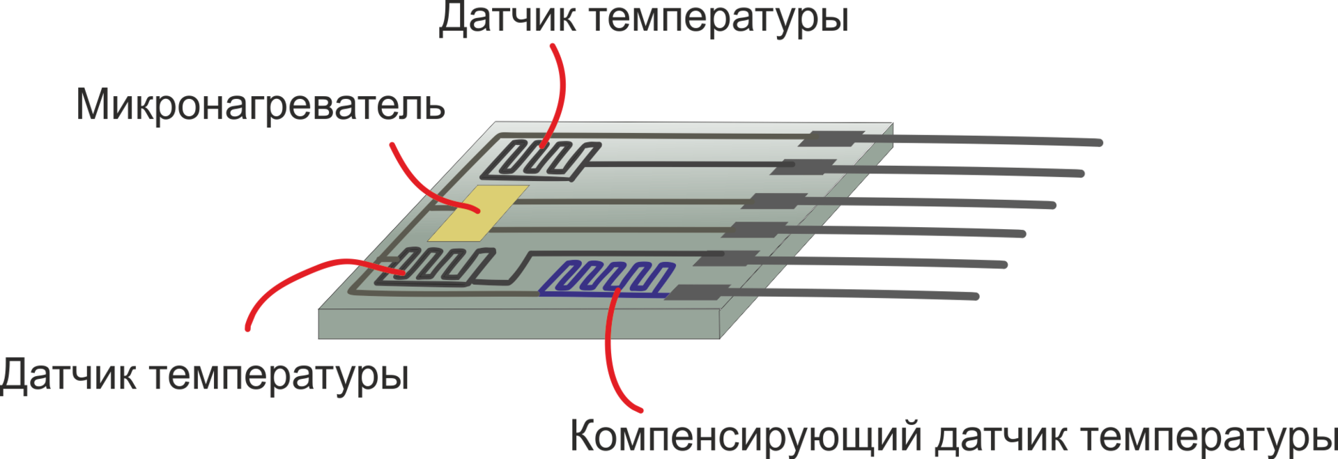
Sensors of the FS2 series are built on this principle. With their help, you can determine both the direction and the flow rate. In the range from 0 to 2.5 m / s, the sensor has a sensitivity of 0.001 m / s.
The measurement range of calorimetric sensors is limited by the principle of its operation - at a certain flow rate, the heat spot “moves” too far and the difference in the indicators of the right and left sensors no longer allows us to judge the flow rate.
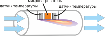
This annoying property of calorimetric sensors is quite simple to bypass. When the flow reaches a certain speed, you can "switch" to work in the hot-wire anemometric mode - start using a pair of heater + compensating temperature sensor according to the already known hot-wire principle.
When using a combination of two measuring methods, the magnitude of the flow velocity over the greater part of the range is determined by a quadratic function of the voltage Uflow (lower graph), and the flow direction is determined by the voltage from the full-bridge circuit consisting of a pair of sensors and a microheater.
If the task does not involve working with flows at a speed of more than 1.5 m / s at all and we are talking about a gaseous medium, then you can use the MFS02 series sensors (Micro Flow Sense). MFS02 has maximum sensitivity (0.0003 m / s) and response speed (response time less than 10 ms).
Structurally, the MFS02 sensor is similar to FS2 and consists of a microheater, a pair of temperature sensors and an additional compensating sensor. However, MFS02 are manufactured according to a different technological process: in the glass-ceramic substrate of the sensor, a zone representing a membrane is allocated. It is assumed that only the membrane is immersed in the flow, therefore, it is on it that the components for calorimetric measurements are located, and a compensating temperature sensor is installed outside the membrane.
The MFS02 sensor has a size of only 3.5 x 5.1 mm, and it is quite difficult to solder to the contact pads, so the MFS02 is also available as part of extension cards that provide access to the terminals of the element.

In conclusion, I will thank the reader for your attention and recall that questions about the use of the products that we write on the Habré can also be sent to the email address specified in my profile.
upd: all mentioned sensors and modules are available from stock. More information on efo-sensor.ru
IST products are not a mass market; they do not produce Among the diverse IST products there is such an interesting thing as flow sensors - flow rate sensors for continuous media. Under the cat I tell you how they work, how they look and why they are needed. I think that it will be interesting not only to flowmeter developers.
So, various physical effects are used to measure the flow of liquids or gases. To measure the flow velocity, mechanical, optical, electromagnetic, ultrasonic and other sensitive elements are used, which make it possible by indirect characteristics to determine the flow rate of a continuous medium passing through a pipe.
Here we note that the flow rate can mean both the volume of the stream (liters per minute or cubic meters per minute), and the mass of the stream (kilogram per minute) or its speed (meters per second). Assuming that in most applications both the characteristics of the medium and the characteristics of the pipe in which the flow moves are known, we will consider all of these concepts to be identical.
Since most of the IST products are platinum temperature sensors (thermal resistance), thermal effects are also used to determine the flow rate.
In heat flow meters, measurements are made either by cooling a heated body placed in the flow (hot-wire anemometers) or by transferring heat energy between two points located along the flow (calorimetric flow meters). Let's see how both principles are used in real applications.
Hot-wire anemometers
Flowmeters with IST hot-wire anemometers are mainly used for gas flows. In the simplest case, they consist of a heating element and a temperature sensor. In fact, these are two thermal resistances, on the basis of which the following algorithm is implemented:
In the absence of a flow, the temperature of the microheater remains unchanged, and in the presence of a flow, the heater begins to give off heat to the external environment. The amount of heat that is given to the flow depends on several factors: on the initial temperature difference of the heater and the medium, on the parameters of the pipe and on the actual flow rate.
Since the temperature difference is determined by the switching circuit of the flow sensor, and we consider the parameters of the pipe unchanged, the heat transfer of the heating element can be used to measure the flow rate.
The heater and temperature sensor are included in the bridge circuit, which is balanced in the absence of flow and unbalanced when the resistance of the heater changes. As the flow rate increases, the heater cools, the bridge is unbalanced, and the unbalance signal is fed to the amplifier. The output of the amplifier tells the heater a higher temperature and brings the bridge back to equilibrium. The same signal is used as an output, i.e. as a function of flow rate.
With the known parameters of the pipe, the position of the sensor, the type of flow, as well as the constant thermophysical characteristics of the gas (composition, pressure, temperature), such a function can be calculated using one of the well-known methods.
The illustration is an example.flow sensor connection diagrams and a graph of the dependence of the Uflow voltage on the flow rate.
Sensors of the FS7 series work by this principle. Conducting paths are applied on a ceramic zirconia substrate - a platinum micro-heater and a temperature sensor, between which connections are provided. The whole structure is covered with a thin insulating layer of glass.
Sensitive elements of this design allow you to measure the flow velocity in the range from 0 to 100 m / s with a sensitivity of 0.01 m / s and an error of less than 3% of the measured value. However, the accuracy of measurements is determined not only by the sensitive element, but also by the circuit of its inclusion, and by the method of calibration of the final device.
The operating temperature range of the FS7 sensor is -20 ... 150 ° C for standard execution, however, IST practices the manufacture of sensors with a permissible temperature up to +400 ° C.
The figure shows two versions of the FS7 sensors - in the case and without it.
About water-containing and aggressive environments
It is important to note that the FS7 sensors, as well as the FS2 discussed below, are used mainly for gases, as well as for liquid media that do not contain water - during prolonged operation in water, the upper insulating layer of the sensor gradually breaks down and electrolysis occurs.
For the flow of water and other similar media, an Out Of Liquid module is provided - an anemometric sensor, the elements of which are isolated from the stream. Out Of Liquid is a small stainless steel tube with a micro heater and a temperature sensor on its outer wall.
The tube has a length of 40 mm and a diameter of 4 mm, the working temperature range of this solution is from -50 ° C to +180 ° C.
About determining the direction of flow
Hot-wire anemometers have some obvious limitations. In particular, they do not allow determining the direction of flow and are not suitable for applications requiring high sensitivity of the sensor.
Calorimetric flow meters, in contrast, are designed for relatively slow gas flows with a variable direction. The calorimetric sensor consists of three elements - a microheater and two sensors that measure the temperature before and after it. In the absence of flow, the heat spot emitted by the heater is stationary, therefore, the continuous medium at the right and left of the heater has the same temperature. When a flow occurs, the heat spot “shifts” according to the direction and speed of the flow. Thus, with known pipe parameters and medium characteristics, the flow rate can be measured by the difference in temperature sensor readings.
In the manufacture of the colorimetric sensor, platinum tracks are also applied to the ceramic substrate and the connections between them - a micro-heater and two temperature sensors.
Since the heating element is cooled in the presence of flow, and this process is no longer used for measurements, an additional temperature compensation sensor is provided on the flow sensor.
Sensors of the FS2 series are built on this principle. With their help, you can determine both the direction and the flow rate. In the range from 0 to 2.5 m / s, the sensor has a sensitivity of 0.001 m / s.
The measurement range of calorimetric sensors is limited by the principle of its operation - at a certain flow rate, the heat spot “moves” too far and the difference in the indicators of the right and left sensors no longer allows us to judge the flow rate.
This annoying property of calorimetric sensors is quite simple to bypass. When the flow reaches a certain speed, you can "switch" to work in the hot-wire anemometric mode - start using a pair of heater + compensating temperature sensor according to the already known hot-wire principle.
When using a combination of two measuring methods, the magnitude of the flow velocity over the greater part of the range is determined by a quadratic function of the voltage Uflow (lower graph), and the flow direction is determined by the voltage from the full-bridge circuit consisting of a pair of sensors and a microheater.
About working with microflows
If the task does not involve working with flows at a speed of more than 1.5 m / s at all and we are talking about a gaseous medium, then you can use the MFS02 series sensors (Micro Flow Sense). MFS02 has maximum sensitivity (0.0003 m / s) and response speed (response time less than 10 ms).
Structurally, the MFS02 sensor is similar to FS2 and consists of a microheater, a pair of temperature sensors and an additional compensating sensor. However, MFS02 are manufactured according to a different technological process: in the glass-ceramic substrate of the sensor, a zone representing a membrane is allocated. It is assumed that only the membrane is immersed in the flow, therefore, it is on it that the components for calorimetric measurements are located, and a compensating temperature sensor is installed outside the membrane.
The MFS02 sensor has a size of only 3.5 x 5.1 mm, and it is quite difficult to solder to the contact pads, so the MFS02 is also available as part of extension cards that provide access to the terminals of the element.
Conclusion
In conclusion, I will thank the reader for your attention and recall that questions about the use of the products that we write on the Habré can also be sent to the email address specified in my profile.
upd: all mentioned sensors and modules are available from stock. More information on efo-sensor.ru