DIY connector for ESP8266 ESP-12
Much has been said, written, and many sites devoted to the ESP8266 module have been created.
Today, adding something new is very difficult. And repeating and voicing what has already been said is not always correct and interesting.
So this module attracted me, and I ordered a few from China. When I realized that this was a huge field for creativity, the task was: how to program it without buying various and not always necessary adapters. Here's what I found a solution:
If you are already interested, then move on.
Soldering wiring and resistances to the module itself, for programming, is not always convenient.
Since in the final version the module can be positioned differently with the elements.
One of my subscribers (user) advised me to pay attention to the connectors on the motherboard. And indeed, I have a whole mountain under their feet (sometimes I’m advancing), I just don’t notice them anymore.


And so I picked up the motherboard and let's apply the module.
And so I found out that the PCI slot is not suitable because of its step.
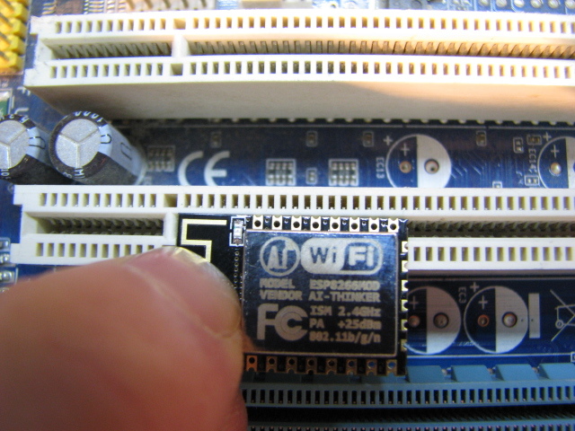
Maybe AGP or PCI-Express might do.

I personally didn’t really like the AGP connector because of the height of the slot.

Therefore, I chose PCI-Express. Yes, and the “motherboard” I have with this slot more, there is something to train on.
To dismantle the slot, you need a hairdryer (280-400 degrees), or a burner, in extreme cases a gas stove will do (I did this before). With poor heating, there are incidents:

Having slightly moved the remains of the “gray matter”, I realized that it was necessary not only to separate the connector, but to provide a seat. And this needs to be done at a level so that contact and pressure are maximum. To do this, sacrifice a symmetrical half, cutting it off at the level of the future site.

Next, a drill is used (not relevant due to high revs), wire cutters and a pulse soldering iron (with copper wire instead of a sting), as well as a clerical knife. We start picking the slot to determine the level of bending for the contact. We try to smoothly cut, from this envy the even landing of the module.

So you need to thin through one contact, gently pulling them to the bottom of the connector (be careful - they are fragile). You also need to roughly form the shape of the connector and provide for the bottom and top to have the body of the slot for gluing (soldering) to each other - do not rush to bite everything off if you do not have several slots in stock.
I glued everything with a pulse soldering iron, it did an excellent job of this task (and I don’t mind the wire on the soldering iron).

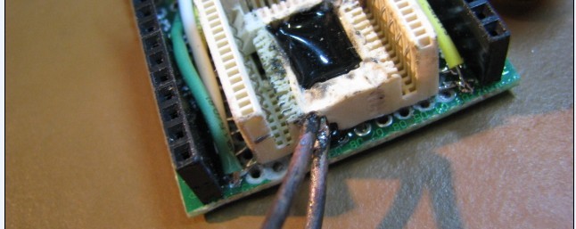
To prevent the U-shaped connector from diverging, when I inserted the module into it, I made an additional jumper from a piece of the slot. So the module has become more reliable.
Hot melt adhesive helped me to securely attach the connector to the board.
I did not have time and there is not always enough space to etch the board, so I used the breadboard PCB board. This option is always convenient when you need to add or remove a part.
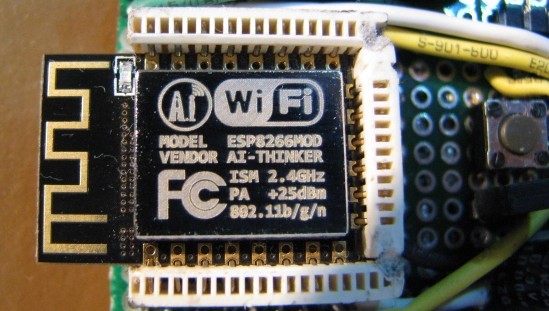
Here's a board I got:
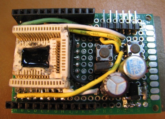
On it, I upload firmware and programs. Now you can use the next menu of modules in various devices.
I used this slot in my video review on ESP8266, there you can clearly see how easy it is with it:
If you have slots and a desire to repeat, then I am sure that you will succeed even better than mine.
Thank you all for your attention, I hope someone will benefit from this idea.
Today, adding something new is very difficult. And repeating and voicing what has already been said is not always correct and interesting.
So this module attracted me, and I ordered a few from China. When I realized that this was a huge field for creativity, the task was: how to program it without buying various and not always necessary adapters. Here's what I found a solution:
If you are already interested, then move on.
Soldering wiring and resistances to the module itself, for programming, is not always convenient.
Since in the final version the module can be positioned differently with the elements.
One of my subscribers (user) advised me to pay attention to the connectors on the motherboard. And indeed, I have a whole mountain under their feet (sometimes I’m advancing), I just don’t notice them anymore.
And so I picked up the motherboard and let's apply the module.
And so I found out that the PCI slot is not suitable because of its step.
Maybe AGP or PCI-Express might do.
I personally didn’t really like the AGP connector because of the height of the slot.
Therefore, I chose PCI-Express. Yes, and the “motherboard” I have with this slot more, there is something to train on.
To dismantle the slot, you need a hairdryer (280-400 degrees), or a burner, in extreme cases a gas stove will do (I did this before). With poor heating, there are incidents:
Having slightly moved the remains of the “gray matter”, I realized that it was necessary not only to separate the connector, but to provide a seat. And this needs to be done at a level so that contact and pressure are maximum. To do this, sacrifice a symmetrical half, cutting it off at the level of the future site.
Next, a drill is used (not relevant due to high revs), wire cutters and a pulse soldering iron (with copper wire instead of a sting), as well as a clerical knife. We start picking the slot to determine the level of bending for the contact. We try to smoothly cut, from this envy the even landing of the module.
So you need to thin through one contact, gently pulling them to the bottom of the connector (be careful - they are fragile). You also need to roughly form the shape of the connector and provide for the bottom and top to have the body of the slot for gluing (soldering) to each other - do not rush to bite everything off if you do not have several slots in stock.
I glued everything with a pulse soldering iron, it did an excellent job of this task (and I don’t mind the wire on the soldering iron).
To prevent the U-shaped connector from diverging, when I inserted the module into it, I made an additional jumper from a piece of the slot. So the module has become more reliable.
Hot melt adhesive helped me to securely attach the connector to the board.
I did not have time and there is not always enough space to etch the board, so I used the breadboard PCB board. This option is always convenient when you need to add or remove a part.
Here's a board I got:
On it, I upload firmware and programs. Now you can use the next menu of modules in various devices.
I used this slot in my video review on ESP8266, there you can clearly see how easy it is with it:
If you have slots and a desire to repeat, then I am sure that you will succeed even better than mine.
Thank you all for your attention, I hope someone will benefit from this idea.