USB bootloader on the microcontroller: updating firmware from a flash drive
It is difficult to overestimate the ability to upgrade firmware on mass-produced products, or on single products in use by the customer. This not only makes it possible to subsequently eliminate bugs and expand the functionality, but also allows the developer with a lighter heart to launch a “still raw” product on the market, if management requires it.
Therefore, the importance of having a bootloader in newly developed devices in most cases is not in doubt. This article will discuss the development of a bootloader via USB on an Atmel SAM D21 microcontroller with a Cortex M0 + core. Specifically on SAMD21J18A. The microcontrollers SAM D20 / 21 do not have a pre-recorded bootloader, so you have to deal with its software implementation. On the Atmel website you can find Application notes , how to make it using standard interfaces (UART, I2C, SPI, USB). Under the cat is a description of the process of creating a USB bootloader.
The address space in the memory of the microcontrollers of the SAMD20 / 21 series is simple:

Non-volatile memory is organized in rows, each row contains 4 pages. The size of 1 page is 64 bytes. Non-volatile memory is erased in rows and recorded page by page. This is important to remember.
The lower (lower) rows in the main address space of non-volatile memory can be used for a bootloader (configured using the BOOTPROT fuses), and the upper rows for emulating EEPROM.
The bootloader section is protected by lock bits and fuses BOOTPROT corresponding to this address space.
BOOTPROT fuses simultaneously determine the size of the bootloader section and protect the allocated memory area from reading.
EEPROM can be written despite the protection of its corresponding memory area.
Note: Atmel Studio version 6.2 (successor of AVR Studio) and ASF framework (Atmel Software Framework) are used as the development environment
In accordance with the USB standard, very accurate clocking is required to implement the bus. We will use an external 32 kHz quartz as a support for DFLL (Digital Frequency Locked Loop). The DFLL output will be used both for clocking the USB module and the entire controller. For the USB module to work, you need to configure DFLL so that the output is exactly 48 MHz. For the stability and accuracy of the DFFL output frequency, it must be configured in closed loop mode.

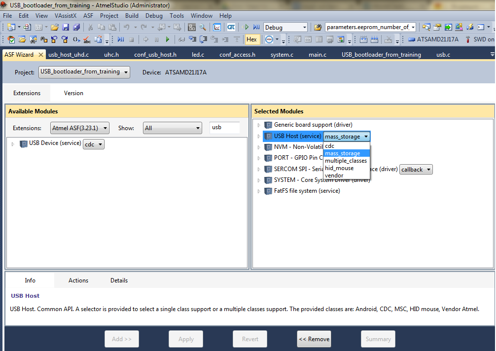
Using the ASF wizard, we connect all the modules we need listed above.
Add USB Host service in mass storage mode .
After adding the driver to the project, several header and executive files appear. We are interested in 2 of them:
For the USB host stack to work, we specify two definitions in the project properties:
To do this, right-click on the project, select Properties -> Toolchain -> ARM / GNU C Compiler -> Symbols .
We comment on the line "#define Lun_usb_unload - NULL" in USB LUNs Definitions in the conf_access.h file to prevent compilation errors.
To track connected devices on the USB bus, a callback is introduced for the Start of Frame event . This interrupt occurs only once every time the SOF is sent, and since the SOF is sent every 1 ms when the device is connected to the bus, this event can be used as a timer.
The interrupt handler is written in the conf_usb_host.h file .
To do this, add the prototype of the main_usb_sof_event () function at the beginning of the conf_usb_host.h file after all # include'ov.
We also add the line to this file:
Now you need to globally define the counter variable in the main.c file , it will be it that will be incremented each time the corresponding handler is called:
Add the actual interrupt handler (callback):
Add the FAT FS file system service (using the ASF wizard). We open the module and select the calendar_polled driver RTC mode .
For the full functioning of the file system module, add main.c at the beginning :
The file name (#define FIRMWARE_FILE "firmware.bin") must match the name of the firmware file on the plug-in flash drive.
Add NVM-Non-volatile memory (driver). In addition, we determine the necessary constants and variables in the main.c file:
Still need to configure a non-volatile memory controller. To do this, add the configuration structure (globally), read the default settings, change the necessary and install (execute in a separate function):
All necessary modules have been added, you can write code.
It is worth noting that if the bootloader uses the same peripherals as the application, then it must be reset before switching to application. Reset is carried out by special functions in ASF.
I also note that you can access a USB device only after 1-2 seconds from the moment it is connected to the bus, since before that the device is initialized.
A brief algorithm of operation (bootloader only) is shown in the figure below:

In SAMD21J18A (as in other SAMD20 / 21 series controllers) each NVM series consists of 4 pages, each of which is 64 bytes. Thus, 200 rows (which we allocate for the bootloader) are (200 * 4 * 64) bytes = 51200 (0xC800) bytes of memory. And the application part should start after 51200 bytes of flash memory.
Partitioning flash memory:
Bootloader section:
Application section:
In order to form the firmware starting from the address we need, and not from the beginning of flash memory, as it happens by default, you need to change the linker file.
The file itself can be found in solution explorer. In our case, it is called samd21j18a_flash.ld :
Path: src-asf-sam0-utils-linker scripts-samd21-gcc
It is necessary to make changes to the definitions of memory areas in it:
Default configuration: must be replaced by Now the compiled binary can be downloaded via the bootloader.
Therefore, the importance of having a bootloader in newly developed devices in most cases is not in doubt. This article will discuss the development of a bootloader via USB on an Atmel SAM D21 microcontroller with a Cortex M0 + core. Specifically on SAMD21J18A. The microcontrollers SAM D20 / 21 do not have a pre-recorded bootloader, so you have to deal with its software implementation. On the Atmel website you can find Application notes , how to make it using standard interfaces (UART, I2C, SPI, USB). Under the cat is a description of the process of creating a USB bootloader.
Formulation of the problem
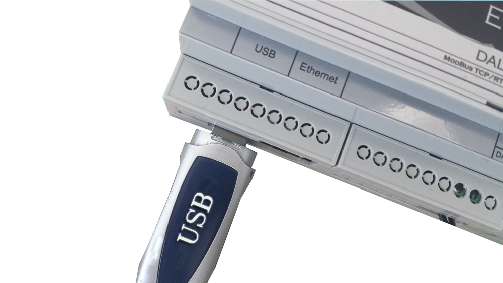
- It is necessary to develop the most simple, from the point of view of the end user, method of updating the firmware of the device. To do this, you need to copy the file with the new firmware to the ordinary USB flash drive, stick the USB flash drive into the device and press the reset button (or reset the power). After that, the bootloader starts, checks for the presence of the firmware file on the USB flash drive and uploads the contents of this file as application
- As a “protection against fool” we use a previously known special name for the firmware file to prevent accidental coincidence of names with other files on the flash drive. Moreover, if the “attacker” independently creates a third-party file with a name that matches the expected one, the device will try to use it as firmware. Of course, in this case, the device’s performance will be impaired, but it can later be restored by slipping the USB flash drive with the correct firmware
- As a USB interface, a hardware USB microcontroller is used.
- The device does not have a permanent Internet connection to download the new firmware on its own
- We believe that connecting a PC to the device and updating the firmware using a third-party utility is more difficult for the end user
A bit of theory and preparation
Memory
The address space in the memory of the microcontrollers of the SAMD20 / 21 series is simple:
Non-volatile memory is organized in rows, each row contains 4 pages. The size of 1 page is 64 bytes. Non-volatile memory is erased in rows and recorded page by page. This is important to remember.
The lower (lower) rows in the main address space of non-volatile memory can be used for a bootloader (configured using the BOOTPROT fuses), and the upper rows for emulating EEPROM.
The bootloader section is protected by lock bits and fuses BOOTPROT corresponding to this address space.
BOOTPROT fuses simultaneously determine the size of the bootloader section and protect the allocated memory area from reading.
EEPROM can be written despite the protection of its corresponding memory area.
What is required to organize a bootloader?
- Work with controller memory - the Non-volatile memory controller (NVM) is responsible for this;
- Work with USB - the USB controller is responsible for this;
- Working with the file system is the power of FATFS.
- And the little things: working with I / O ports, clocking.
Note: Atmel Studio version 6.2 (successor of AVR Studio) and ASF framework (Atmel Software Framework) are used as the development environment
USB subtleties
In accordance with the USB standard, very accurate clocking is required to implement the bus. We will use an external 32 kHz quartz as a support for DFLL (Digital Frequency Locked Loop). The DFLL output will be used both for clocking the USB module and the entire controller. For the USB module to work, you need to configure DFLL so that the output is exactly 48 MHz. For the stability and accuracy of the DFFL output frequency, it must be configured in closed loop mode.
Putting together a project
Using the ASF wizard, we connect all the modules we need listed above.
USB host
Add USB Host service in mass storage mode .
After adding the driver to the project, several header and executive files appear. We are interested in 2 of them:
- conf_usb_host.h - configures USB and configures interrupt handlers (Callback),
- conf_access.h - Configures the abstract layer for working with memory.
For the USB host stack to work, we specify two definitions in the project properties:
USB_MASS_STORAGE_ENABLE=true
ACCESS_MEM_TO_RAM_ENABLED=true
To do this, right-click on the project, select Properties -> Toolchain -> ARM / GNU C Compiler -> Symbols .
We comment on the line "#define Lun_usb_unload - NULL" in USB LUNs Definitions in the conf_access.h file to prevent compilation errors.
To track connected devices on the USB bus, a callback is introduced for the Start of Frame event . This interrupt occurs only once every time the SOF is sent, and since the SOF is sent every 1 ms when the device is connected to the bus, this event can be used as a timer.
The interrupt handler is written in the conf_usb_host.h file .
To do this, add the prototype of the main_usb_sof_event () function at the beginning of the conf_usb_host.h file after all # include'ov.
void main_usb_sof_event(void);
We also add the line to this file:
# define UHC_SOF_EVENT() main_usb_sof_event()
Now you need to globally define the counter variable in the main.c file , it will be it that will be incremented each time the corresponding handler is called:
volatile static uint16_t main_usb_sof_counter = 0;
Add the actual interrupt handler (callback):
void main_usb_sof_event(void)
{
   main_usb_sof_counter++;
}
File system
Add the FAT FS file system service (using the ASF wizard). We open the module and select the calendar_polled driver RTC mode .
For the full functioning of the file system module, add main.c at the beginning :
#include "string.h"
#define MAX_DRIVE _VOLUMES
#define FIRMWARE_FILE "firmware.bin"
const char firmware_filename[] = {FIRMWARE_FILE};
/* FATFS variables */
static FATFS fs;
static FILE file_object;
The file name (#define FIRMWARE_FILE "firmware.bin") must match the name of the firmware file on the plug-in flash drive.
Work with non-volatile memory
Add NVM-Non-volatile memory (driver). In addition, we determine the necessary constants and variables in the main.c file:
#define APP_START_ADDRESS (NVMCTRL_ROW_SIZE * 200)
uint8_t page_buffer[NVMCTRL_PAGE_SIZE];
Still need to configure a non-volatile memory controller. To do this, add the configuration structure (globally), read the default settings, change the necessary and install (execute in a separate function):
struct nvm_config nvm_cfg;
void nvm_init(void)
{
	nvm_get_config_defaults(&nvm_cfg);
	nvm_cfg.manual_page_write=false;
	nvm_set_config(&nvm_cfg);
}
All necessary modules have been added, you can write code.
The code
It is worth noting that if the bootloader uses the same peripherals as the application, then it must be reset before switching to application. Reset is carried out by special functions in ASF.
I also note that you can access a USB device only after 1-2 seconds from the moment it is connected to the bus, since before that the device is initialized.
A brief algorithm of operation (bootloader only) is shown in the figure below:
Main code
#include
#include
#include
#include "string.h"
//------------------------------------------------------------------------------------------------------------------------------
#define MAX_DRIVE _VOLUMES
#define FIRMWARE_FILE "Modbus_RTU_TCP.bin"
#define APP_START_ADDRESS (NVMCTRL_ROW_SIZE * 200)
//------------------------------------------------------------------------------------------------------------------------------
const char firmware_filename[] = {FIRMWARE_FILE};
// FATFS variables
static FATFS fs;
static FIL file_object;
// NVM
uint8_t page_buffer[NVMCTRL_PAGE_SIZE];
struct nvm_config nvm_cfg;
//USB
volatile static uint16_t main_usb_sof_counter = 0;
//------------------------------------------------------------------------------------------------------------------------------
void main_usb_sof_event(void)
{
	main_usb_sof_counter++;
}
static void check_boot_mode(void)
{
	uint32_t app_check_address;
	uint32_t *app_check_address_ptr;
	// Check if WDT is locked
	if (!(WDT->CTRL.reg & WDT_CTRL_ALWAYSON))
	{
		//Disable the Watchdog module
		WDT->CTRL.reg &= ~WDT_CTRL_ENABLE;
	}
	app_check_address = APP_START_ADDRESS;
	app_check_address_ptr = (uint32_t *)app_check_address;
	if (*app_check_address_ptr == 0xFFFFFFFF)
	{
		// No application; run bootloader
		return;
	}
	// Pointer to the Application Section
	void (*application_code_entry)(void);
	// Rebase the Stack Pointer
	__set_MSP(*(uint32_t *)APP_START_ADDRESS);
	// Rebase the vector table base address TODO: use RAM
	SCB->VTOR = ((uint32_t)APP_START_ADDRESS & SCB_VTOR_TBLOFF_Msk);
	// Load the Reset Handler address of the application
	application_code_entry = (void (*)(void))(unsigned *)(*(unsigned *)(APP_START_ADDRESS + 4));
	//Jump to user Reset Handler in the application
	application_code_entry();
}
void delay_ms(uint32_t ms)
{
	volatile int a=0;
	for(uint32_t i=0; i 2000)
	    {
		   main_usb_sof_counter = 0;
		   volatile uint8_t lun = LUN_ID_USB;
		   // Mount drive
		   memset(&fs, 0, sizeof(FATFS));
		   FRESULT res = f_mount(lun, &fs);
		   if (FR_INVALID_DRIVE == res)
		   {
			  continue;
		   }
		   res = f_open(&file_object,firmware_filename, FA_READ);
		   if (res == FR_NOT_READY)
		   {
			   // LUN not ready
			  f_close(&file_object);
			  continue;
		   }
		   if (res != FR_OK)
		   {
			   // LUN test error
			  f_close(&file_object);
			  continue;
		   }
		   // Get size of file
		   fw_size = f_size(&file_object);
	 	   bytes_read = 0;
		   if (fw_size != 0)
		   {
			  current_page = APP_START_ADDRESS /NVMCTRL_PAGE_SIZE;
			  curr_address = 0;
			  // Erase flash rows to fit new firmware
			  rows_clear = fw_size / NVMCTRL_ROW_SIZE;
			  for (i = 0; i < rows_clear; i++)
			  {
				do {
					error_code = nvm_erase_row(	(APP_START_ADDRESS) +(NVMCTRL_ROW_SIZE * i));
				} while (error_code == STATUS_BUSY);
			  }
			  do {
				    //Read data from USB stick to the page buffer
				    f_read(&file_object,page_buffer,NVMCTRL_PAGE_SIZE,&bytes_read );
			        bytes_read=64;
				    curr_address += bytes_read;
				    // Write page buffer to flash
				    do {
					      error_code = nvm_write_buffer(current_page * NVMCTRL_PAGE_SIZE,	page_buffer, bytes_read);
				   } while (error_code == STATUS_BUSY);
				    current_page++;
			    } while (curr_address < fw_size);
	    }
		f_close(&file_object);
		system_interrupt_disable_global();
		uhc_stop(1);
		NVIC_SystemReset();
	  }
	}
}
Preparing the firmware file
In SAMD21J18A (as in other SAMD20 / 21 series controllers) each NVM series consists of 4 pages, each of which is 64 bytes. Thus, 200 rows (which we allocate for the bootloader) are (200 * 4 * 64) bytes = 51200 (0xC800) bytes of memory. And the application part should start after 51200 bytes of flash memory.
Partitioning flash memory:
Bootloader section:
- Size: 50 KB (51200 bytes)
- Address space (flash memory): 0x00000000 to 0x0000C7FF
Application section:
- Size: 206 KB (256KB-50KB)
- Address space (flash memory): 0x0000C800 to 0x0003FFFF
In order to form the firmware starting from the address we need, and not from the beginning of flash memory, as it happens by default, you need to change the linker file.
The file itself can be found in solution explorer. In our case, it is called samd21j18a_flash.ld :
Path: src-asf-sam0-utils-linker scripts-samd21-gcc
It is necessary to make changes to the definitions of memory areas in it:
Default configuration: must be replaced by Now the compiled binary can be downloaded via the bootloader.
rom (rx) : ORIGIN = 0x00000000,

LENGTH = 0x00040000
rom (rx) : ORIGIN = 0x0000C800,

LENGTH = 0x00033800