January 12, 2016 at 15:28
A little more about the errors of ACS design and PLC programming
I came across this article and since the subject of the discussion is very interesting, I will allow myself to develop this topic a little.
Let's take the same circuit (indeed, rather clumsy, I hope the author will forgive me for using it) from the mentioned post:
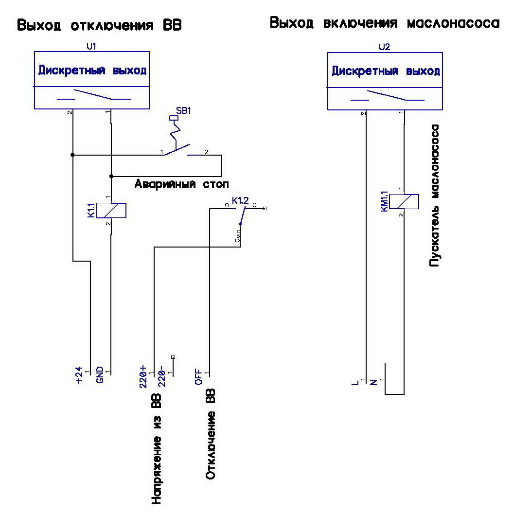
The first weak link of this circuit that caught my eye is not K1 relay at all, of course also worth mentioning, but the inscription “Emergency stop” is normal -open contact button SB1.
It is easy to imagine that a dangling cable from this button itself will cause the operator to press it until the pulse is lost, until the equipment rises from overheating, or while the circular saw completes the work of his colleague, or presses it with a hydraulic press.
Helixaredid the circuit at the end of the post, but this error remained.
Let's go a little deeper:
When designing ACS systems, and especially emergency stop components, you need to be guided not by the arguments “either this way or that”, but by clearly written standards. To describe them in their entirety is not for Habr, but let's take a quick look.
EN 60204 describes three categories of emergency shutdown:
- (0) uncontrolled shutdown by immediately turning off the power;
- (1) stop while maintaining power until the drive stops;
- (2) controlled stop.
According to EN 418, emergency stop and emergency shutdown are distinguished. The easiest way to separate them is by source of danger. If something moves, it means a stop with an emergency stop. If the danger is due to electric shock, shutdown with emergency shutdown (oil-oil, yeah).
Finally, the command device (in this case the same button) should be self-locking with the release of conscious action "in place".
Uff, four paragraphs of text about one contact ...
Before you open AutoCad and draw a diagram, it would be right to conduct a risk analysis, take into account the experience of emergencies, read about systematic failures, changes in standards, safety requirements, determine SIL, etc., you can continue for a long time. But in the context of some Chelyabinsk Metallurgical Plant, this seems unlikely, unfortunately.
Therefore, we will go from the most important limitation, the budget, having determined that the main priorities for us are:
- the integrity of the arms and legs of our colleague;
- integrity of equipment;
- minimum intervention in the budget.
Dichalt will now run over and say that the first two points are confused ...
In the article to which I refer, the author uses Siemens equipment, also my favorite for a number of reasons. We continue with the same equipment, but instead of the strange button SB1 we take the correct one, i.e. mushroom-shaped push-button emergency stop switch with latching with two groups of contacts. We will use normally-closed ones.
In addition, we change the controller, and take not 314, but for example 315F. The letter F stands for Failsafe. In short, these are fault-tolerant controllers specifically tuned for security. Of course, such controllers can also be used for ordinary control tasks, separating the safe and insecure parts of hardware and software.
We will connect our S1 button as one two-channel sensor with a rating of 1oo1, as shown in the diagram (sorry for the notes with a pencil and handwriting):

Now, let's move on to the second part of the story, i.e. PLC programming and errors.
In order to program our safety function (emergency stop), we need Step7 with the Distributed Safety package installed. The main difference from programming the line of “ordinary controllers” is the lack of my favorite STL language, the absence of some operations with numbers and in general, the trimming of any functionality, writing of which can cause a programmer difficulty or error. In stock we have only F-LAD and F-FBD.
The simplest program with 6 buttons, 5 light bulbs and 2 contactors using Distributed Safety becomes like this:

However, for this example, we will consider one standard FB 215 “F_ESTOP1” program block: Emergency STOP up to Stop Category 1.
The meaning of a separate, secure software unit for processing one emergency stop button is very simple. Firstly, the programmer will not be mistaken, and secondly, this unit, just like the hardware into which we load it, is certified and guaranteed to work as it should.
The block interface is simple. The help for him is as follows:

The principle of operation is described on the screen, but for those who do not know English, I will explain the call to this block in our example.
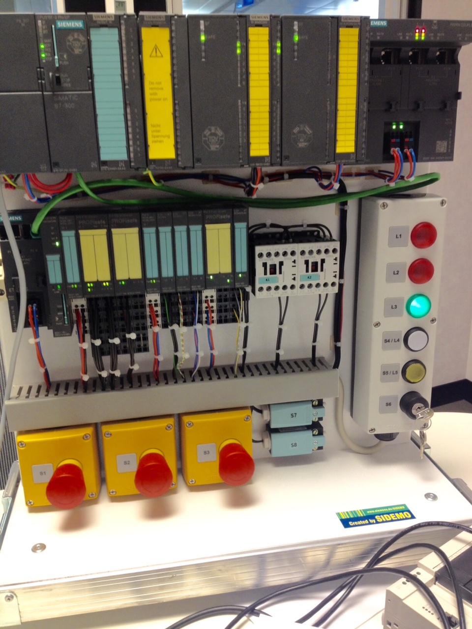
So, the button, 4/8 FDI input module, output module and contactors K1, K2. Below you will find a beautiful picture with our example in hardware.
We call the block and bind the addresses:
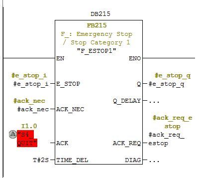
Here the main thing is the input #e_stop_i - this is the signal from our button. The operation of any of its contacts will result in a unit at this input. The output #e_stop_q is then bound to the output module and to the contactors. The main thing is behind. In addition, there is a need for confirmation, that is, after the button is triggered, the operator must not just squeeze it to its initial position by turning "in place", but also confirm the reset with another button, key, or mouse click on the HMI interface.
We save, compile, call, fill in and other actions with the ending -em (sorry, lunch is close) - voila. An emergency stop system is ready, which will turn off our saw or press in case of pressing a button, cable break, diagnostic error, loss of communication, power, module malfunction, and much more.
Here it is, in the form of a ready-made stand, which helps to understand the details of safe design and programming:
Since I like comments, here are a couple of questions for your attentiveness and quick wits:
1. Why is there one address in the call to the F_ESTOP1 block red?
2. How would you connect the contactors K1 and K2?
Thanks!
Postscript: next time I will write about contacts S7 / S8)
Let's take the same circuit (
The first weak link of this circuit that caught my eye is not K1 relay at all, of course also worth mentioning, but the inscription “Emergency stop” is normal -open contact button SB1.
It is easy to imagine that a dangling cable from this button itself will cause the operator to press it until the pulse is lost, until the equipment rises from overheating, or while the circular saw completes the work of his colleague, or presses it with a hydraulic press.
Helixaredid the circuit at the end of the post, but this error remained.
Let's go a little deeper:
When designing ACS systems, and especially emergency stop components, you need to be guided not by the arguments “either this way or that”, but by clearly written standards. To describe them in their entirety is not for Habr, but let's take a quick look.
EN 60204 describes three categories of emergency shutdown:
- (0) uncontrolled shutdown by immediately turning off the power;
- (1) stop while maintaining power until the drive stops;
- (2) controlled stop.
According to EN 418, emergency stop and emergency shutdown are distinguished. The easiest way to separate them is by source of danger. If something moves, it means a stop with an emergency stop. If the danger is due to electric shock, shutdown with emergency shutdown (oil-oil, yeah).
Finally, the command device (in this case the same button) should be self-locking with the release of conscious action "in place".
Uff, four paragraphs of text about one contact ...
Before you open AutoCad and draw a diagram, it would be right to conduct a risk analysis, take into account the experience of emergencies, read about systematic failures, changes in standards, safety requirements, determine SIL, etc., you can continue for a long time. But in the context of some Chelyabinsk Metallurgical Plant, this seems unlikely, unfortunately.
Therefore, we will go from the most important limitation, the budget, having determined that the main priorities for us are:
- the integrity of the arms and legs of our colleague;
- integrity of equipment;
- minimum intervention in the budget.
Dichalt will now run over and say that the first two points are confused ...
In the article to which I refer, the author uses Siemens equipment, also my favorite for a number of reasons. We continue with the same equipment, but instead of the strange button SB1 we take the correct one, i.e. mushroom-shaped push-button emergency stop switch with latching with two groups of contacts. We will use normally-closed ones.
In addition, we change the controller, and take not 314, but for example 315F. The letter F stands for Failsafe. In short, these are fault-tolerant controllers specifically tuned for security. Of course, such controllers can also be used for ordinary control tasks, separating the safe and insecure parts of hardware and software.
We will connect our S1 button as one two-channel sensor with a rating of 1oo1, as shown in the diagram (sorry for the notes with a pencil and handwriting):
Now, let's move on to the second part of the story, i.e. PLC programming and errors.
In order to program our safety function (emergency stop), we need Step7 with the Distributed Safety package installed. The main difference from programming the line of “ordinary controllers” is the lack of my favorite STL language, the absence of some operations with numbers and in general, the trimming of any functionality, writing of which can cause a programmer difficulty or error. In stock we have only F-LAD and F-FBD.
The simplest program with 6 buttons, 5 light bulbs and 2 contactors using Distributed Safety becomes like this:
However, for this example, we will consider one standard FB 215 “F_ESTOP1” program block: Emergency STOP up to Stop Category 1.
The meaning of a separate, secure software unit for processing one emergency stop button is very simple. Firstly, the programmer will not be mistaken, and secondly, this unit, just like the hardware into which we load it, is certified and guaranteed to work as it should.
The block interface is simple. The help for him is as follows:
The principle of operation is described on the screen, but for those who do not know English, I will explain the call to this block in our example.
So, the button, 4/8 FDI input module, output module and contactors K1, K2. Below you will find a beautiful picture with our example in hardware.
We call the block and bind the addresses:
Here the main thing is the input #e_stop_i - this is the signal from our button. The operation of any of its contacts will result in a unit at this input. The output #e_stop_q is then bound to the output module and to the contactors. The main thing is behind. In addition, there is a need for confirmation, that is, after the button is triggered, the operator must not just squeeze it to its initial position by turning "in place", but also confirm the reset with another button, key, or mouse click on the HMI interface.
We save, compile, call, fill in and other actions with the ending -em (sorry, lunch is close) - voila. An emergency stop system is ready, which will turn off our saw or press in case of pressing a button, cable break, diagnostic error, loss of communication, power, module malfunction, and much more.
Here it is, in the form of a ready-made stand, which helps to understand the details of safe design and programming:
Since I like comments, here are a couple of questions for your attentiveness and quick wits:
1. Why is there one address in the call to the F_ESTOP1 block red?
2. How would you connect the contactors K1 and K2?
Thanks!
Postscript: next time I will write about contacts S7 / S8)