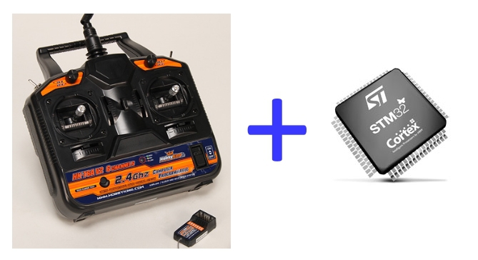
Connecting the STM32 to the radio control equipment
I needed to implement remote control of several DC motors.
In stores, ready-made radio control kits are available for various riding-flying toys and "not toys", and there was a desire to use just such a control.
The signals at the output of the receiver of such a set are pulses for controlling servo machines,
and the task is to measure the pulse duration of 0.8..2.3 ms in each of the six channels, spending as little controller resources as possible.
The following describes how to measure the duration of pulses from six channels using the peripheral features of STM32 microcontrollers.
The hardware on which debugging was performed was HobbyKing HK-T6A radio control equipment and STM32F100C8T controller.
At the output of the receiver we have these signals: The

obvious solution is to start 6 timers and measure each channel with a separate timer.
On the leading edge of the pulse, reset the timer, start the countdown. On the trailing edge, we look at how much the timer has counted since the reset, this will be the pulse duration.
To reduce the number of timers involved, let's try to create several channels for one timer, but so that there is as little software processing as possible.
We will use the timer mode to work with the Hall sensor.
Brushless motors sometimes have three hall sensors mounted with offset as a rotor position sensor. The picture below gives a visual image of how this happens.
To process the hall sensor of a brushless motor, some timers in STM32 can be set in such a way that:
- on the rising edge on any of the three inputs CC1, CC2, CC3, the timer is reset,
- on the falling edge, on any of these inputs, in the capture compare register CCMR1 latches the value of the timer counter - in fact, the pulse duration.
Thus, in one register, we sequentially have the values of the pulse duration over three channels.
You can programmatically separate these values, but it’s easier to leave only two channels ch2 and ch3, the values from them will be latched into CCR2 and CCR3 registers, and the timer will be reset on the rising edge on any of these channels.
The pin, to which the input ch1 is assigned, is set to the output so as not to catch interference on an unused input.
In the figure below: the red arrow shows the path of the timer reset signal, the green arrows show the path of the click signal of the timer value.

As a result, for reading 6 channels we will use 3 timers , and without additional software tricks, in the CCR timer registers we have the required values. A little surprise. When all this was already implemented, but once again I forgot the pinout of the output of the receiver, then when I searched the Internet I came across an interesting picture. Taken from here Having studied the Internet, I made a discovery for myself.

It turned out that the input used to power and bind the receiver to the transmitter has a signal at the output that combines all 6 outputs.
Only it is necessary to measure not the duration of the pulses, but the time between pulses.

It is called PPM and is widely used to connect radio control equipment to a computer as a joystick for a simulator (via an adapter, of course).
There are different versions of adapters, and even based on an inexpensive USBasp programmer.
With a PPM output, the task was simplified: measure the time between six consecutive pulses, the start of the measurement will be a sufficiently long pause.
On the leading edge of the pulse, save the timer value and immediately reset the timer.
When no pulses are received, an overflow occurs in the timer overflow, at this moment we are preparing to receive pulses, configure DMA so that 7 values are added to the array.
The first pulse synchronizes the measurement process, the value of the timer at this moment does not interest us, the next 6 values will store the time between pulses.
With each subsequent pulse, the timer value is latched, the timer is reset, the latched value by DMA is stored in the array.
We display all the measurement results in the first and second way in UART, see what works, reacts to the deviations of the handles.

When the handles are deflected, the values change in the range of 3200..5700 units
Only the values measured by the first and second methods differ, but the logic analyzer shows the same thing, so these are the features of the equipment.
Rake, which managed to step in the development process.
The behavior of the program looks like this - when the power is turned on, the program works, but when working with the debugger, it crashes to HardFault_Handler. The programmer is connected via a SWD line (SWDIO, SWIO, GND).
It turned out:
- during the reset, the programmer does not clear the timer status register TIM1-> SR, there are interrupt request flags,
- when the timer is initialized, an interrupt from TIM1 is allowed,
- the interrupt for TIM1 and TIM15 is common, and when we access the htim15 structure, it still not defined, so fly away to HardFault_Handler.
This is what the interrupt procedure looks like
void TIM1_BRK_TIM15_IRQHandler (void)
{
/ * USER CODE BEGIN TIM1_BRK_TIM15_IRQn 0 * /
/ * USER CODE END TIM1_BRK_TIM15_IRQn 0 * /
HAL_TIM_IRQHandler (& htim1);
HAL_TIM_IRQHandler (& htim15);
/ * USER CODE BEGIN TIM1_BRK_TIM15_IRQn 1 * /
/ * USER CODE END TIM1_BRK_TIM15_IRQn 1 * /
}
{
/ * USER CODE BEGIN TIM1_BRK_TIM15_IRQn 0 * /
/ * USER CODE END TIM1_BRK_TIM15_IRQn 0 * /
HAL_TIM_IRQHandler (& htim1);
HAL_TIM_IRQHandler (& htim15);
/ * USER CODE BEGIN TIM1_BRK_TIM15_IRQn 1 * /
/ * USER CODE END TIM1_BRK_TIM15_IRQn 1 * /
}
All this code was generated automatically by Cub, so I had to add the line htim15.Instance = TIM15 before all initialization.
Applications:
1. Project for Cube
2. Data of 6 channels + PPM saved from Logic-U USB analyzer