November 18, 2015 at 13:12
Cisco UCS Initial Setup Overview

It is generally accepted that Cisco UCS server solutions are very complex. We decided to demonstrate the simplicity of customizing such solutions. Under the cutscene, a video review, as well as a transcript with screenshots (Caution, traffic! Many screenshots are full size, if you squeeze them - do not parse anything) .
Disclaimer: of course, the entire process of configuring a Cisco blade takes about 2 hours, we noted the key and main points. Can you imagine all this live recording? - It will not be interesting to anyone.
The video review itself
Transcript (with a little editing)
Today we look at the basic configuration of the Cisco blade system. For several years, these systems have excited the market. First, let's see how the boxes and the basic kit look.

A small educational program on the blade system from Cisco.
Firstly, these are 2 universal switches that can transmit traffic and Ethernet and FibreChannel, they are built on the basis of Cisco Nexus.
The second component is the blade chassis itself and the servers that are installed in that chassis. The peculiarity of the system is that we need a maximum of two universal Fabric Interconnect switches (hereinafter referred to as FI), for almost any number of servers that we will have in the data center.

For example, we need 1, 2, 10, 20 chassis, all the same, only two of the above switches will be enough for us. This is a huge savings for large enterprises.
What is the feature? If suddenly we need two Ethernet ports for each server, 4, 10, 100 Ethernet ports that are responsible for each server, or FibreChannel does not matter how many, we still need only two such FI switches. This is done thanks to Cisco technology, which allows you to see from the management console any number of interfaces that we will create on each server.
They are created virtually, but, for the software environment, they are visible as hardware components. Likewise for switches.
Now software tune We
connect a console cable already familiar to many.

We will connect it to each switch for configuration.
Further customization is through the web interface.
Pay attention to the back side of the blade chassis. You can observe here a special FI extension module called Fabric Extender.

In order for the chassis to connect to FI, an extender is used - it simply extends the switch with an additional number of ports from the blade servers. Now in our configuration, each switch is connected to the extender using four 10-gigabit connections.

If necessary, we can dynamically reduce / increase the number of connections - to change the speed of connection to the chassis. A second extender is used for backup.
First, we are asked how we want to configure it: through the console, new / old settings, password, etc.

We try to enter a simple password "password", and I am asked to enter a more complex option.
Next is a survey from the system: will there be a second FI switch? Next, we assign which of them is the first, and which is the second. Then is the name of the system. We give IP addresses, for what we connected to them with the console. The address of the first switch: 192.168.0.11, gateway: 192.168.0.1
Now, the interesting thing is the virtual address 192.168.0.1, which will move between the switches if one of them fails. DNS will not configure yet.
Then we are asked: “do we like everything in the configuration?”, We say yes, and the configuration is applied. Configuration from the console is complete.
Now set up the second FI factories.
We will configure from the console. Another FI was found, the question is - can I download a configuration from it? Download. Then set the IP address of the second FI.
Choosing a configuration application. Configuration from the console is complete. All further configuration will be done with a graphical interface. The only thing you need a console for is setting up IP addresses.

Enter the IP address that we configured from the console in the browser. The Java console starts.

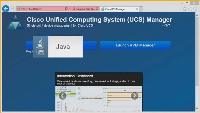
Enter the username and password that we set from the console. And here we see the graphical control interface of our entire system. Now we see two FIs. They are clustered. We do not see servers yet.

Let's deal with the management interface.
We can see which ports are on which FI interfaces - which of them are FC now, which Ethernet.
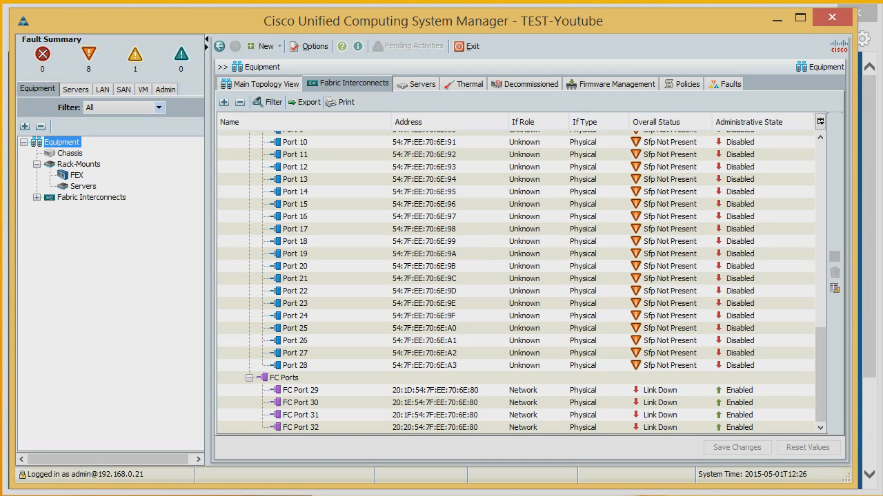
Information on heat dissipation - here you can see if everything is normal with the cooling system, power supplies.

And now the firmware management menu. From here we can centrally update or lower the firmware on certain components.
Here the firmware is downloaded and applied immediately.
You can download the new firmware from the local system or via FTP, SFTP.

Now the politicians menu. The first policy is 10 gigabit links. Whether to connect them to the Port Channel or not. Set to connect. From here, you can specify the redundancy of the power supplies and some other parameters.

Now we will make our servers visible. To do this, those ports on the switches that go to the blade chassis must be assigned a special server type.

Here are the first four ports, they are connected to the blade chassis.

Open the port and set it as server.

Thus, we activate all ports.
Since in the politicians we have appointed that all ports that go to the blade chassis will be assembled via the Port Channel, we get two 40-gigabit links. One will go from one switch, another from the second.
Now configure the second FI. Ports going to the chassis can be located anywhere - at the beginning, in the middle or at the end, as we assign them, it will be so.
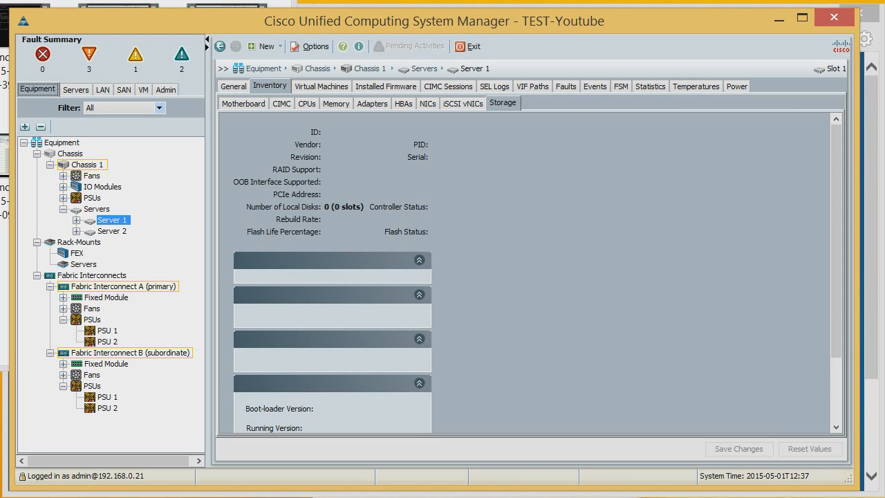
Let's see what was discovered through the activated ports.
There are two servers. We can see what serial numbers they have, on the adapters that are inserted into them, on the CIMC version (an analogue of iLo from Cisco). You can also see information on the processors in the servers.

You can see the memory, RAID-controllers, locally mounted drives.

Now let's get started with the setup. The first thing we will do is create MAC addresses for our servers. What is it for? We can reflash absolutely all server hardware settings. We create the first pool of MAC addresses, and give the MAC system that we already had and on which security was configured. Exactly one MAC address.

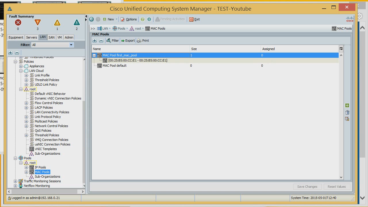
If you already had some kind of configured system, we can create a new server with such MAC addresses, and there will be no need to reconfigure the network.
Let's create another pool where it will be possible to create many MAC addresses - say, 256. The
pool of MAC addresses that we will assign to the servers is ready.
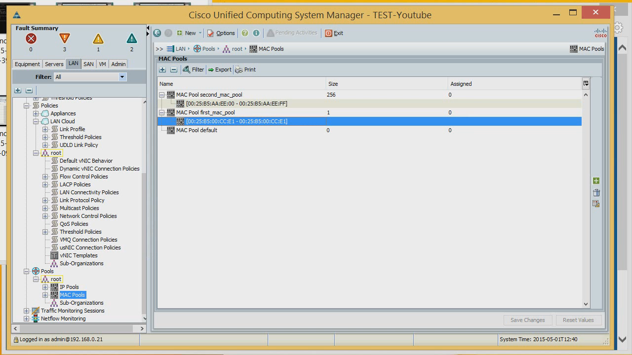
Next, create the IP addresses that will be used to manage the servers. We already have a predefined list of external controls.
Let's add here a block of IP addresses that will be managing for the servers. There will be ten in the block. Assign Default Gateway.

To show that we can have more addresses besides the first pool, we will create one more pool.

Now we have a list of MAC addresses and IP addresses that we will give to the servers. The next thing that may be required is setting up the adapter adapters, i.e. Host Bus adapters. Let's create WWNNs. We already have a list ready, let's create another one. Let’s think of a random value, for example 256.
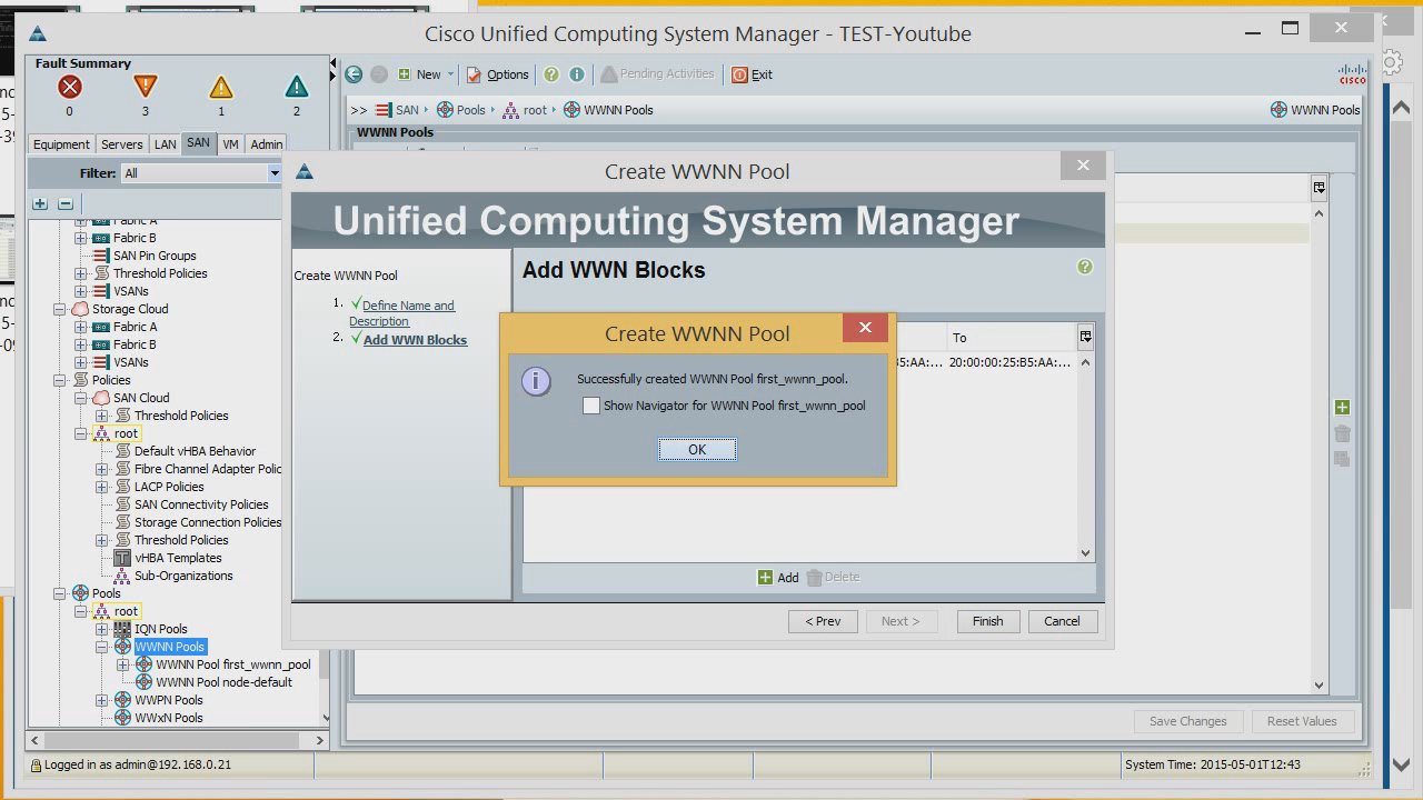
Now a list of portnames.


We have all the basic settings. What are we still missing? The server serial number or its UID is missing. They are assigned in the server section.
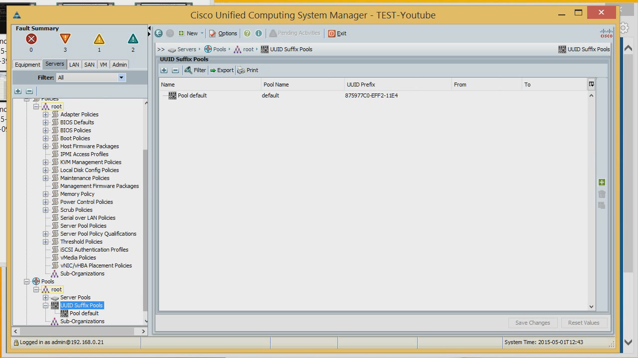
By default, the UID is flashed into the server at the factory by the manufacturer, and it cannot be changed in the future. And in our case it’s possible. You can make either one UID or a pool, which will be assigned to our servers in turn.

Now create the server itself. Select expert mode. We give the server, or profile, which we will apply to the server, a name. A profile is what the server itself will look like. Select from the list the UID that has already been created. Click Next.

Further there is an opportunity to choose dynamic network adapters. These are adapters that are used in VMware and which can be dynamically added or removed. And now we are creating not dynamic, but static IP addresses. There is also an MTU setting for this adapter and some tuning for a specific operating system. Suppose we have VMware.


Let's create a couple more adapters in the systems - let there be four.

Now setting up the storage system. By default, we don’t have any disks here, so we’ll create a special policy that will display so that the server does not use any disks at all. We can choose in which RAID to collect disks on the server, or indicate that they do not exist at all. There are no SD cards either, that's why we put Disable. And we choose to apply the newly created policy to this profile.

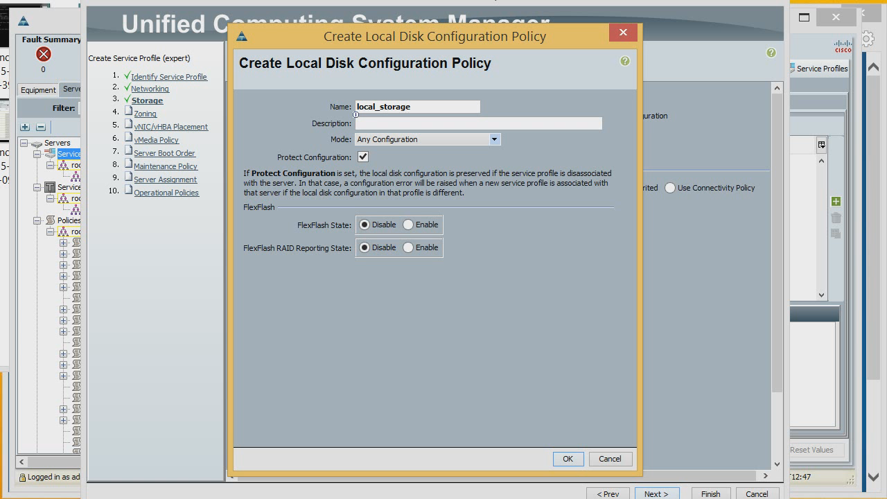
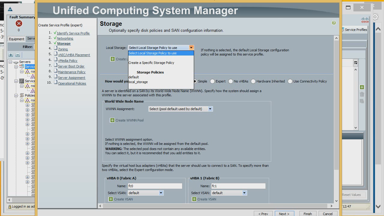
Now let's create the Host Bus adapters in expert mode. WWNN we take from the list created by us. We give the adapter a name and a portname from the list of portnames. It will be connected to FI A. We can connect it to a specific vSAN, and assign optimization to a specific policy.

In the same way, create another adapter. Next, we can configure the zoning, but so far we have no connection to the storage system, omit this step. It can be done later.
Setting the queue for adapters to appear on the system and what kind of interruption they will occupy.

Now - setting up server loading, from where the OS will be loaded. There are several boot policies by default, but let's create our own. To do this, select Create a Specific Boot Policy. First, set the default boot from a CD / DVD connected via CIMC, add the name, boot from the null adapter (fc0). If we click Add SAN Boot Target, we can specify additional boot settings. We now have two adapters, in the future it will be possible to add from which specific target to load.
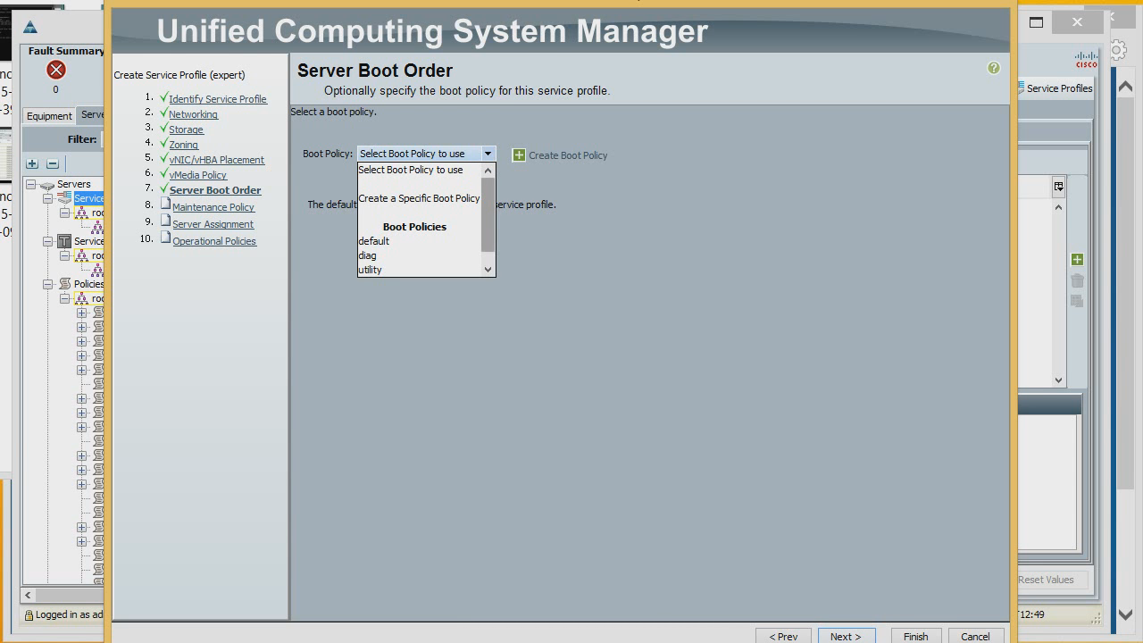

We select our newly created policy to use it for the server profile.

Immediately move on to the last step - setting up the BIOS of the newly created server. Let's create some new profile to see what we can assign and see in the BIOS settings of the created profile and server. First, standard parameters, such as Quiet Boot, what to do with Post Error, what to do when there is power loss, processor properties, enable / disable Hyper Threading, virtualization technologies, etc. Then, memory, serial port, USB, PCI, QPI settings , built-in adapters (what to do with them and how to perceive them), download settings.


As you can see, most of the parameters that are in the BIOS can be assigned, and they will be immediately applied to the server.
Moreover, the profiles can be applied both to one server, and immediately to several, and accordingly immediately propagated to all servers.
Here we choose which IP address or pool of IP addresses to use for external administration.

Actually, the profile has been created.
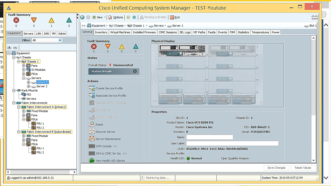
Now we can apply it. After a few minutes, our server is fully consistent with the profile that we created.


Using the KVM console, you can see what is happening on the server itself.

All questions about [email protected] solutions
It is worth noting that Cisco solutions through a group of companies are now available not only in Ukraine but also in Moldova - a distribution contract has recently been signed in this country.
Training courses / workshops / workshops in various areas of IT infrastructure - Training center MUK (Kiev)
MUK-service - client and corporate IT repair, service contracts