Real-time debugging via JTAG / SWJ-DP for ARM Cortex-M core microcontrollers

For some time now, Segger has been offering Real Time Terminal (RTT) technology for its J-Link J-Link adapters. Its essence is that the program on the microcontroller can output and receive debugging information from the JTAG / SWJ-DP port, as is usually done through UART. And then we no longer need a real debugging UART. Further, a little more about the capabilities of this technology.
The ability to output debugging information to the JTAG / SWJ-DP port was implemented as soon as the port itself appeared on the microcontrollers. There are two ways to do this: use the semihosting technique or the Serial Wire Output (SWO) technique .
Using semihostingleads to the substitution of input / output channels of standard file operations of the C language. This is not always acceptable, since file operations in the application may already be used for another purpose. Also, semihosting must explicitly disable and recompile the project when releasing the release version.
On top of that, semihosting provides the slowest data transfer of the technologies discussed here.
Using Serial Wire Output is simpler than semihosting, however, it requires the use of an additional SWO signal from the JTAG / SWJ-DP port, and also necessitates recompilation when switching to the release version, i.e. version without connecting a debugger. The SWO output functions are synchronous, i.e. They expect port readiness and do not have the necessary determinism.
Segger’s Real Time Terminal technology makes it even easier to output debugging information via SWJ-DP and provides the following amenities :
• Only two external lines are enough — these are SW CLK and SW DIO.
• All additional code in the microcontroller takes no more than 500 bytes, if you do not use input, then even 300 bytes.
• No recompilation is required for the release version, the debug output functions are asynchronous and practically do not take up processor time and do not have any effect on the progress of the program if the debug adapter is not connected.
• The speed of debug I / O is very high.
• Debug I / O can be redirected to any third-party terminal emulator program that supports the telnet protocol.
• Segger provides free terminal emulator, logger and telnet client utilities for connecting to a microcontroller via a debug adapter without having to run third-party IDEs with debuggers.
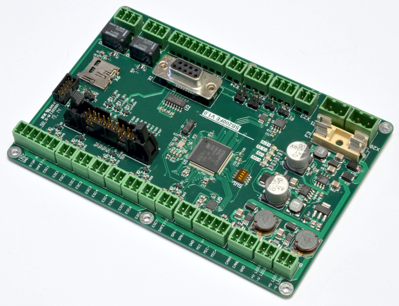
An example of using RTT.
In the figure above, the controller board is based on the STM32F745VET6 chip. External quartz 16 MHz. The core frequency is 168 MHz.
Debugging was required for the bootloader via the CAN bus. There is a RS232 serial port connected to the UART, but it is also used for the bootloader. To output debugging information to it would mean greatly modifying the debugging version of the program compared to the release version. With a lack of time, this is extremely undesirable.
To connect RTT, the following steps were performed:
- RTT source code taken ( http://download.segger.com/J-Link/RTT/RTT_Implementation_141217.zip )
- Sources are unpacked and copied to the project directory called RTT. The project itself was carried out in the environment of Keil MDK ARM
- Sources are connected to the project. Added files SEGGER_RTT.h and SEGGER_RTT_Conf.h to the general list of project header files
- Additional settings were made in the file SEGGER_RTT_Conf.h: the value of BUFFER_SIZE_UP was increased to 2048, the value of SEGGER_RTT_PRINTF_BUFFER_SIZE was increased to 512. The parameters actually iterated until the indicated buffers overflowed.
- Editing bootloader sources. In all places of interest, calls to the SEGGER_RTT_printf function were inserted with the necessary messages. I used this function as the most convenient, although it introduces significant stack consumption and a certain delay in data conversion. But in my case it was acceptable.
- Since debugging was needed even when programming internal Flash, I transferred the RTT code to the microcontroller RAM. To do this, in all 2 source files, RTT introduced a directive
#pragma arm section code = "CODE_IN_RAM",
and in the linker file .sct defined this area as follows:RW_IRAM1 0x20000000 0x00010000
{
.ANY (+ RW + ZI)
* (CODE_IN_RAM)
} - Defined absolute structure address for directive SEGGER_RTT_CB as directive
static SEGGER_RTT_CB _SEGGER_RTT __attribute __ ((at (0x20000000)))
- Compiled the project. After compilation, it turned out that the RTT code in RAM took 400 bytes with zero optimization.
- I inserted the JLinkRTTViewer.exe utility call into the Keil IDE tool menu
- Since I prefer to use TeraTerm as a term emulator, I inserted a call to it in the menu. The call line is as follows:
”C: / Program Files (x86) /teraterm/ttermpro.exe” / T = 1 telnet: // localhost: 19021 / X = 0 / Y = 0 / W = "J-Link RTT"
Throughput
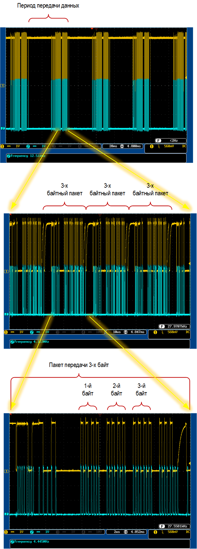
It seemed interesting at what speed information is output to the terminal emulator through a debugging adapter using RTT. Waveforms were taken from the SW SLK and SW DIO signals.
It turned out that J-Link uses polling with a frequency of about 40 ms. For data transmission is used no more than 50% of this period. In a data block transmitted over a period, packets carrying useful data also occupy no more than 50% of the time. Packets carry no more than 3 bytes of useful data. Three bytes of useful data in a packet also occupy no more than 50% of its length. Total we get: 0.5 * 0.5 * 0.5 = 0.125 i.e. 12.5% of the bandwidth of the SW channel is used to transmit debug output.
The channel frequency above 4 MHz in J-Link could not be raised under any settings. This means that we have a maximum transmission rate of 4 Mbps. Of these, only 4 * 0.125 = 0.5 i.e. 500 Kbps can at best be used for debugging output. This, of course, is not much compared to the actual debugging UART, which can transmit at speeds of several Mbps, but everything has a price.