Homemade control unit for diesel engine
Cars have long overgrown with all kinds of electronics, so overgrown that it’s just horrible: in the doors of the controller, in the headlights of the controller, in the brakes of the controller, well, in the engine, as if without it. Usually, when it comes to the engine control unit (ECU), a gasoline engine is hung, hung with sensors, actuators, and wire harnesses. The control unit sensitively reads the parameters of the sensors, adjusts the mixture and the beginning of sparking. Difficult! But enthusiasts create their own control units, write alternative firmware to squeeze out the extra “pony”, to bypass some kind of malfunction, or simply to improve skills. Moreover, as a rule, circumstances push the authors to such a step, for example, dissatisfaction with the contact ignition system of gasoline engines, a light shortage of electrics, and so on.
It is about such circumstances and aboutdiesel engine and it will be discussed.
So, the statement of the problem:
Given:
- Diesel engine with mechanical pump DW8, manufactured by PSA, 2000 The pump is dead from time to time.
- A new fuel pump, purchased on occasion, with electronically controlled injection timing from a modification to the DW8B motor (The same circumstances).
- The complete absence of wiring for electronic control, the control unit itself.
- The desire to deal with the simple electronics of the pump, to raise the skill, to study more deeply the operation of such pumps.
Requires: serviceable engine after the "fusion".
Bit of theory
Previously, when diesel engines were large, they were controlled by in-line high pressure pumps. Everything is very simple - for each cylinder a plunger that presses the fuel through the nozzle. A camshaft presses on the plunger, which has a variable cam lift height, so engine control is obtained.
Then they began to make pumps more complicated, distributed type. There are one or two plungers there, fuel under pressure is already distributed among the cylinders by a special mechanism. Management is more complicated, but still mechanical - the throttle lever and all.
Completely electronic injection systems were replaced by mechanical ones - each injector opens upon command from the control unit, accurately dosing fuel and providing well the most environmentally friendly and economical engine operation mode.
My pump is stuck somewhere between a mechanical distribution and an electronic one. In fact - a rotary type distribution pump (manufactured by Lucas-Delphi), with one single actuating element: injection advance valve.
When I first purchased the pump, I did not attach importance to the strange solenoid in the side of the pump, and decided to “become”.
What kind of injection lead? As it turned out later, an unusually important parameter in the operation of the engine. It depends on acceleration, and maximum speed, and engine consumption. An analogue on gasoline engines is UOZ (ignition timing).
The essence of this injection angle is simple: it takes time to burn the fuel in the cylinder. The higher the engine speed, the less time the fuel has, and therefore it must be injected into the cylinder early, so that after the piston passes through the TDC, the fuel will already burn and give energy to the flywheel. At low revs, on the contrary, it is necessary to inject fuel directly at the TDC so that it does not begin to burn in advance, and does not create a load on the piston going up. On a cold engine, the intake must be done earlier, on a hot engine - later. Under load - earlier (more fuel), without - later. Here is such a science in one parameter.
A quick google showed a rather meager amount of information on regulatory options - obviously this is the lot of the developers of fuel equipment, even repairmen do not operate on any theory. Especially sad with the absolute values of the angles - for different engines, the values are slightly different, and everything is covered in darkness of secrecy.
Understanding began to be built from this diagram:
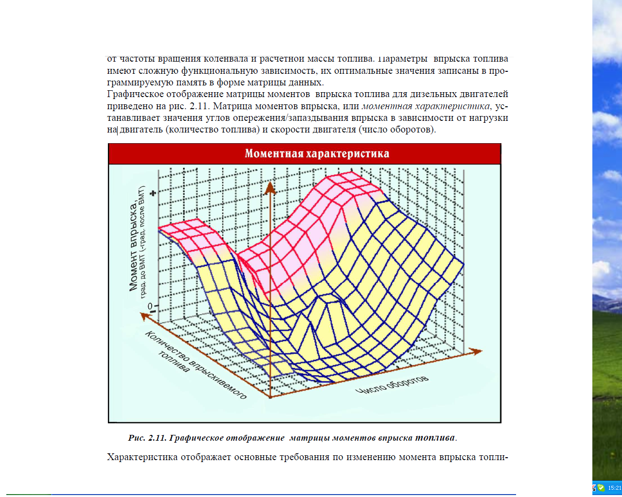
Well, with the exception of the absence of absolute values, nothing complicated.
Along with theoretical studies, it was worth looking at the mechanical analogue of this entire system - since it is in the old pump. The injection timing mechanism there is very simple, even elegant. The piston pushed by the fuel pressure in the pump housing is supported by a spring and is connected to the actuator - the lead ring. With increasing revolutions, the pressure on the piston increases and it shifts the injection to the earlier side. With increasing load, exactly the same thing happens. In addition, the stiffness of the spring changes when you press the gas pedal - the more the pedal is pressed, the weaker the spring, and the larger the angle. Now it remains only to realize the same in the form of electronics, which means it is time to evaluate what is available from the sensors and actuators.
The easiest way is with the latter. There are exactly one of them, an injection timing valve, two wires. It is a solenoid that unlocks the fuel line, thereby lowering the pressure on the lead ring in the pump. A fully open valve corresponds to a minimum lead, closed - to a maximum. Regulation is performed using PWM at a frequency of about 50Hz. The degree of adjustment is high, with this valve you can extend the whole tooth on the timing belt, a range of about 25-30 degrees. This is a plus. Of the minuses, one filling angle corresponds to different values of the control signal filling, depending on the fuel temperature. This automatically excludes an open regulation system, which means it's time to look at the sensors.
So, the main parameter that is controlled by the system is the current ignition timing. Angle means the value in degrees between something and something. A diesel engine has two sensors: a crankshaft position sensor and a needle lift sensor in the nozzle of the first cylinder.
The sensors in my engine are inductive. Here is a picture that roughly corresponds to the crankshaft position sensor:
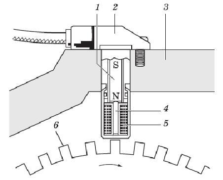
The sensor winding is magnetized by a permanent magnet, or by direct current through a coil. A change in the distance from the sensor to the soft magnetic obstacle causes a change in the current through the coil, and can be registered as a voltage pulse at the output of the sensor. It is remarkable that in this way it is possible to fix both the approximation of the mark (positive momentum) and the distance (negative).
However, on diesel cars, this sensor is made a little differently - in the picture the sensor interacts with the teeth on the flywheel, in my case there are two recesses on the flywheel opposite the sensor in diameter. They give two pulses per revolution of the flywheel, which means 4 pulses per revolution of the shaft of the fuel pump. I learned this simple wisdom when I received a signal 4 times the calculated frequency. There is a plus in this approach: since there are 4 pulses, the signal can be removed from any nozzle.
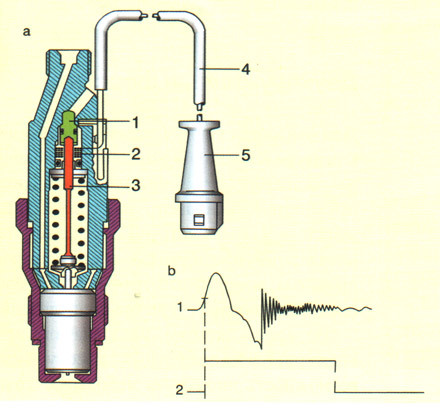
The needle lift sensor is made in the same way, but in the nozzle body. Fuel, under pressure, undermines the needle of the atomizer, while simultaneously inducing a weak impulse in the nozzle coil.
So, for a minimum system performance, two sensors are needed. In my car there was (fortunately) one - a crankshaft position sensor. The nozzle with the sensor had to be purchased separately, fortunately, it costs absolutely nothing to disassemble.
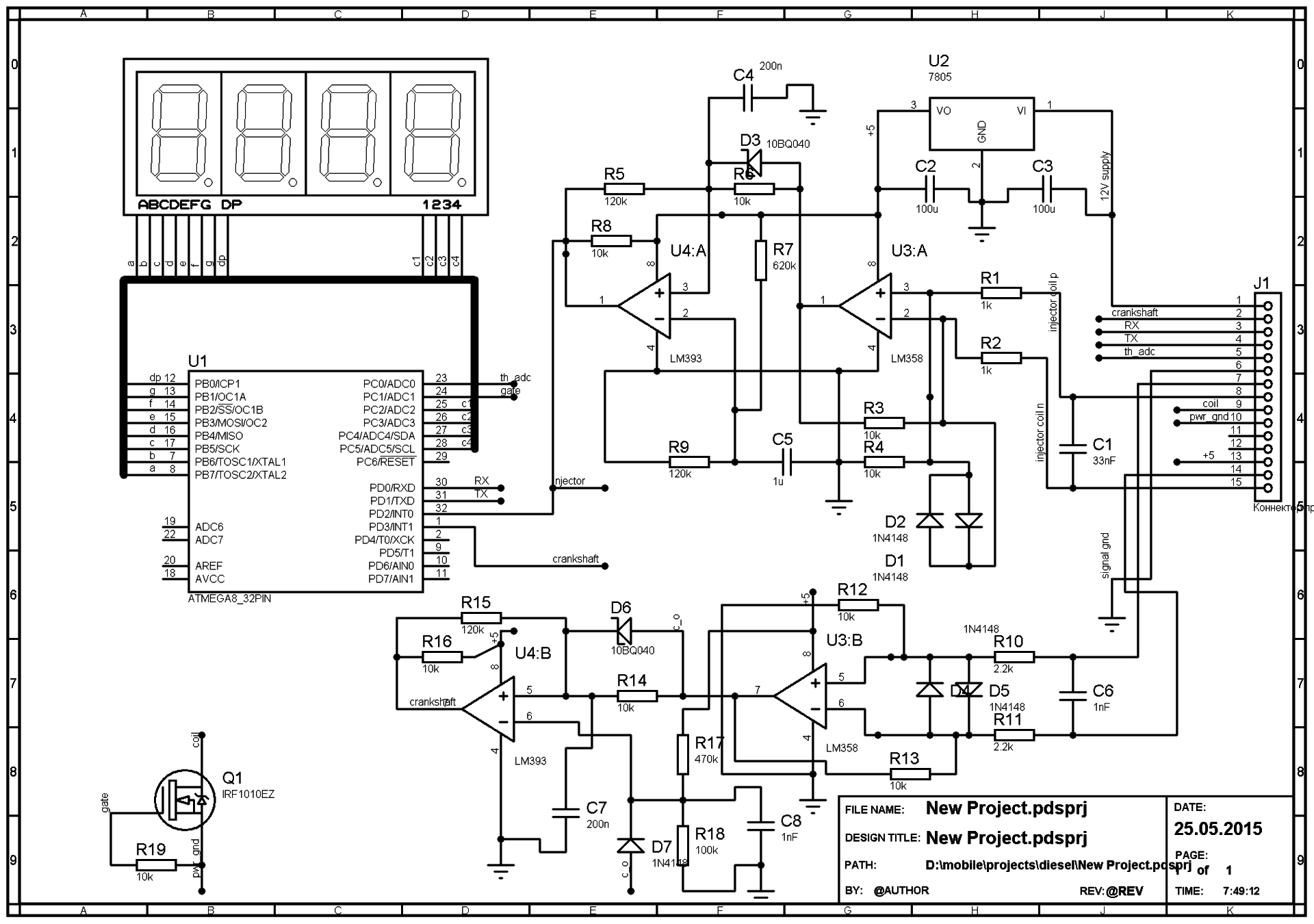
Now the signals must be processed and entered into the controller, another difficulty. The difficulty is because there is nothing to see on the Internet for the finished circuitry of the input circuits. In the midst of design, a simple signal conditioner was assembled on the knee: a differential amplifier on the LM358 and a Schmidt trigger. The gain was chosen at random, and was approximately 50. What a joy it was when I received a completely normal signal from both sensors!
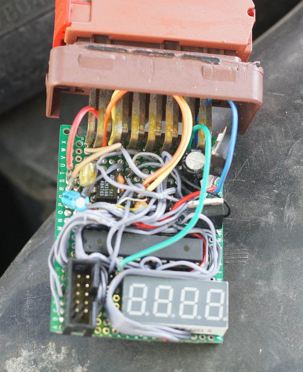
It was time to evaluate the real engine parameters. Also on the knee was assembled the simplest angle meter between two signals with an acceptable accuracy of 1 degree. Design - ATMEGA8A microcontroller and seven-segment indicator for clarity.
The data was a little strange. So, the maximum lead according to my device is 25 degrees, the minimum one at which the engine does not stall is 8. This did not fit into the graph from the beginning of the article, where negative values of the lead angle appear. I had to make a strobe to check if anyone was breached. It turned out that it does not breach, just the marks on the flywheel are shifted relative to TDC by about 10 degrees.
Oh, something is too much “about” to adjust one parameter. First, a dependency graph in parrots, and then an unknown constant. The engine tuning “by ear”, “by smell” and by reaction to the pedal came to the rescue. Joy was added by the fact that experienced diesel engineers on the forums give exactly the opposite advice on tuning. For many, the ringing of pistons and the loud operation of the engine is an injection delay, but in fact it is just the opposite. Crazy diesel traction "on the bottoms" - a consequence of excessive advancing injection, in fact - on the contrary. The following conclusions were drawn from my own experience:
At low speeds, the angle should be minimal, the border can be detected when starting a completely cold engine. If it stalls after turning off the glow plugs - the angle is too late, increase the lead. In my parrots it's 8-9 degrees. With this setting, the engine does not stall when the clutch pedal is released sharply, pulls at idle even in 4th gear, well, in general, beauty. Such a static angle is not suitable for comfortable work for one reason - it is impossible to spin the engine above 1,500 rpm, and at the same time it warms up terribly, throwing diesel fuel into the exhaust pipe.
The upper limit was also found experimentally, an angle of about 25 degrees allows the engine at high speeds not only to spin, but also to accelerate the car. At the same time, there is no characteristic clatter of pistons, the smell of exhaust has a healthy, slightly “Kamaz” smell, no sour meat and black smoke. This indirectly means that the diesel fuel burned out completely, while not at too high temperatures.
It's time to put it all together, beautifully designed and rolled back the control unit. However, the joy was short-lived. At first I found out that the simplest signal driver from the nozzle crashes very much and gives a burst of pulses instead of one when the speed increases to 1800-2000 rpm, neither protective diodes, nor cable shielding, nor a game with a gain factor helped to combat this , nor the assembly of a typical shaper circuit of a gasoline ECU. The search for a solution to this problem periodically pops up on the Internet. In the same place, the correct train of thought was suggested - to use a specialized microcircuit.
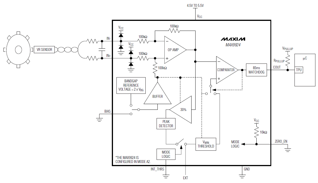
It is called MAX9926, it is a whole line of specialized ICs for crankshaft position sensors, ABS sensors and other inductive sensors. According to reviews - well, just a panacea, pulls a useful signal from the noise level and in the presence of interference. However, I could not find her at the place of residence (I didn’t even hear it), or order from China (expensive and only large parties). But there is a datasheet with an internal structure, why not repeat it?
As a result, such a scheme was born:
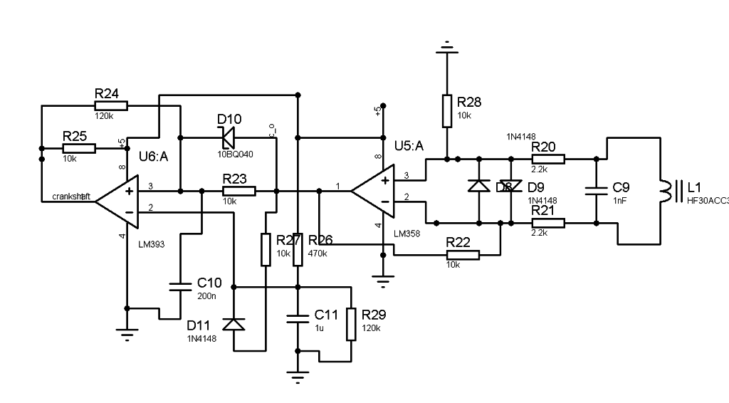
A little explanation
On the U5 chip, a differential amplifier with moderate gain is assembled. There are no features here, except that unipolar power supply without shear resistors, they are not needed for this op-amp.
The interesting part is compiled on the comparator U6. In fact, this is a basic single-shot comparator with a latch. Hysteresis is introduced by resistor R24, and resistor R23 and diode D10 delay the trailing edge of the signal by about 5ms, which allows you to ignore all signals with a repetition rate above 200 Hz.
The reference input of the comparator hangs at a variable potential, thanks to the diode D11 and resistors R26, R27. The higher the signal level at the input of the comparator, the higher the threshold for its operation. This solves the problem of different levels of the useful signal depending on the engine speed.
It worked! Now, without interference, a signal is received from the nozzle and from the crankshaft sensor. It's time to adjust the injection timing. Obviously, the PID controller just begs to regulate . Complexity, as always, is in its configuration.
Some numerical methods for calculating PID coefficients are divided into the complete absence of any data on the pump response to control. So you need to pick up. They all start with a proportional coefficient, having tried the value 1, I already saw the operation of the regulator. The reaction time of such a regulator is depressing, a given angle is set in about 3-4 seconds and has a tendency to fluctuations. Everything would be fine, but in this application it is possible to make a regulatory error in the direction of advancing, but not a degree in the direction of delay. The delay in the angle is especially painful at high speeds, the car seemed to only be traveling 100 km / h, but it is already braking the engine like brakes. Then I introduced a direct proportional coefficient and an inverse, 4 times larger. When the angle goes into delay, the controller quickly returns it to safe values.
P and I coefficients were selected "by eye" according to the criterion of the absence of self-oscillations.
The law of changing the lead angle from revolutions is so far clogged not in the table, but obeys a linear law, without any frills. It will come down to check, and there you can get confused.
The gas pedal sensor in the pump is made in the form of a variable resistor on the axis of the pump arm, the resistor slider is connected to the ADC of the microcontroller. Pressing the pedal “to the floor” changes the set angle by 2 degrees. It feels like the most, engine throttle response and speed are good.
About iron
Since processes in this regulator flow slowly, special speed is not required. The task was handled by the MEGA8A AVR microcontroller at a frequency of only 1 MHz. He comfortably manages to read the PID, process interruptions by sensors, display the current angle on a seven-segment indicator, and output debugging information to the serial port.
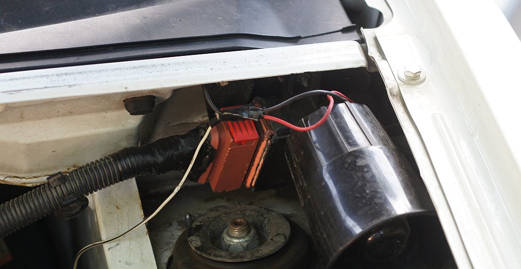
The device, first assembled on anything and hanging on the wires from the motor, migrated to the cultural building of the tachometer control unit, which was released by the way. It was released not just like that, but along with a sealed 15-pin connector, where the "braid" of the motor was brought up, and the standard tachometer now receives a signal from a new shaper.
In general, it is possible and necessary to summarize.
The development is definitely a success. A couple of hundred kilometers on the new pump showed no difference in behavior compared to the old, mechanical one. Fuel consumption even fell slightly, and amounted to a pleasant 7.5l per hundred in the urban cycle.
Countless skills have been gained, both in the theory of fuel equipment and in the programming of microcontrollers.
Future plans
Despite the law of life, "the best enemy of the good," the control unit shines improvements. Firstly, the algorithm does not take into account several parameters, namely: engine temperature and the amount of fuel injected. With the first parameter, everything is clear, it’s only worth connecting a standard coolant temperature sensor, then with the second you will have to change the controller circuit greatly. The fact is that the load on the engine can be caught by analyzing the negative emission on the signal from the nozzle. It corresponds to locking the nozzle, which means that by calculating the length of the open state of the nozzle, you can estimate both fuel consumption and load. Only for this current microcontroller is not enough, there are not enough interrupt inputs.
UPD:
The article forgot to mention the important difference between a diesel engine and a gasoline engine. In a gasoline engine, the preparation of the fuel mixture begins with air . Hence the mandatory attributes of any ECU for bezin: air pressure sensor (relative or absolute), flow meter, temperature sensor. Adjustment of the engine is also air - throttle.
On a diesel engine, the mixture is always depleted; there is no question of any stoichiometric composition of the mixture. In any mode, there is enough air, this is laid down by the very design of the diesel engine. Adjustment is made exclusively by the amount of fuel, and air does not need to be taken into account when the computer is running. The situation has changed for Common Rail diesels, where air is considered the same as on gasoline, although errors in the amount of air for diesels are not critical.
Resources:
1. Hot debate on the forum about the lead angle with bits of information
2. Similar concerns of owners of gasoline engines, spied circuitry
3. Programming the PID controller
4. Charts from a live nozzle
5. Sources on GitHub
6. Entire controller circuit