PwrBlock Open-Source Programmable Power Supply: First Prototype Tests & Key Specs
PwrBlock is an open-source, programmable power supply designed for test benches and automated electronics validation. The project has moved from schematics to working hardware: prototypes have been assembled, core operating modes tested, and key specifications verified. The unit delivers stable, precisely monitored power—no modifications required to commercial instruments.
Key Block Components
The prototype prioritizes compactness, measurement accuracy, and interface-based control. Core elements include:
- TPS25983 Protection IC: 2.7–26 V input range; integrated FET switch with 2.7 mΩ on-resistance at 20 A.
- STM32G0C1CE Microcontroller: Cortex-M0+ @ 64 MHz, 512 KB flash, built-in USB Type-C PD controller—eliminates need for a separate PD chip.
- INA229 Current/Voltage Monitor: Up to 85 V, 20-bit resolution, SPI interface, threshold-triggered interrupts, ±1°C internal temperature sensor. Measures current, voltage, power, and energy—fully factory-calibrated, zero user calibration needed.
- LM51772 DC-DC Converter: Buck-boost topology, I²C-configurable.
// Example typical I²C command for LM51772 configuration (pseudocode)
write_i2c(0x40, REG_VOUT, 32000);  // 32 V
write_i2c(0x40, REG_ILIM, 3000);   // 3 A
Together, these components deliver an output voltage range of 1–32 V and up to 3 A continuous current.
Maximum-Power Stress Test
The prototype was run continuously at 32 V / 3 A (96 W output) for 3 hours. Test conditions: lab bench supply (not mains), electronic load, bare PCB—no enclosure or heatsink.
Results:
| Parameter | Value |
|-----------|--------|
| Input power | 103.64 W |
| Output power | 96.17 W |
| Efficiency | 92.7% |
| Power loss | 7.47 W |
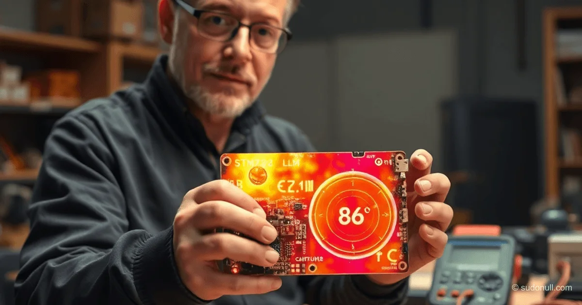
Efficiency matches theoretical predictions. Thermal imaging showed: inductor case at 80°C, DC-DC IC at 71–72°C, bottom-side thermal pads at 86°C. The inductor is rated to 165°C—no thermal stress observed. Recommendations: reinforce inductor mounting and add thermal interface material for improved heat transfer.
Voltage & Current Regulation
Voltage is set digitally via I²C: 10 mV step (1–24 V), 20 mV step (3.3–32 V). An undocumented but fully functional analog fine-tuning feature is available via the LM51772’s ATRK pin—enabling 1 mV resolution.
For current limiting, the LM51772 supports average-current regulation using an external shunt, configured over I²C (50 mA step). Below 500 mA, hardware regulation is unavailable. Alternatives:
- External ISET resistor driven by MCU DAC: enables sub-mA analog control—but introduces 6.5 kHz ripple below 500 mA.
- Shunt replacement: lowers minimum regulated current to 250 mA, extends max current to 3.5 A.
- Software-controlled constant-current (CC) mode for currents under 250 mA.
Hardware CC range: 250 mA – 3 A. Digital step size: 25 mA.
Enclosure & Mechanical Design
Enclosure fabricated from 1 mm anodized aluminum: laser-etched labeling, rigidity sufficient for low-volume production. PCB mounts via standoffs with integrated thermal pads. Issue identified: anodization insulates ground contacts—requires localized abrasion for reliable grounding. Mounting holes added for integration into standard test fixtures. Power button upgraded to tactile click-type with LED backlighting.
Key Takeaways
- 92.7% efficiency at 96 W—verified under uncooled, real-world stress conditions.
- Precision regulation: 1 mV voltage resolution, down to 25 mA digital current steps.
- INA229 delivers factory-trusted 20-bit measurements—zero calibration required.
- Fully open source: build it yourself, modify freely, extend functionality.
- Hardware current limiting starts at 250 mA; lower currents supported via software CC mode.
Next Steps
Upcoming development priorities:
- Thermal chamber and EMC compliance testing.
- Dynamic response optimization.
- Robust software CC implementation for ultra-low currents (<250 mA).
- Firmware finalization and release.
- Fixture design for high-throughput board-level validation.
PwrBlock integrates seamlessly into modular test benches alongside other open-source building blocks (e.g., programmer, DAQ). Next in line: CmptBlock—a Raspberry Pi Compute Module–based I/O and metrology unit.
— Editorial Team










No comments yet.