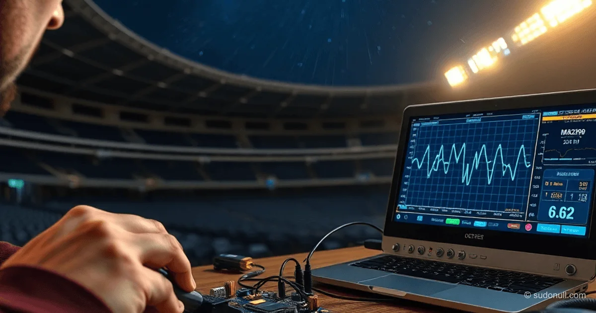
Building an SDR GPS Receiver on STM32 Without Specialized Chips
The STM32F4 can capture and process a 2-bit data stream from the GNSS RF front-end MAX2769 at 16.368 MHz in real time. The entire chain from ADC to correlation is implemented in software—no ASICs or FPGAs—using DMA and optimized bit operations.
GNSS Receiver Architecture
Traditional GPS receivers rely on dedicated correlators like the GP2021 to find PRN code correlation peaks. This project replaces that hardware chain with an MCU:
- RF front-end (MAX2769) digitizes the signal at IF 4.092 MHz
- DMA captures data into a circular buffer
- Software processing: carrier wipeoff, code wipeoff, correlation
One PRN period (1 ms) holds 16368 samples—exactly 16 per chip (1023 chips). Bit-packed data is grouped into 2 bytes per chip.
Hardware: MAX2769 Front-End
The MAX2769 in Preconfigured Device State mode (PGM=1, variant 2) outputs a one-bit sign signal on I1 without SPI setup. The board includes:
- TCXO at 16.368 MHz
- 3.0V LDO
- Active antenna on J3
- Clock output on P5
- Data on P3
Frequencies are chosen for perfect alignment: 16368 / 1023 = 16 samples/chip. Ideal chip pattern on IF: 0b1100110011001100.
Data Capture on STM32F4-Discovery
The STM32F4 (Cortex-M4, 168 MHz, 192 KB RAM, 1 MB Flash) uses SPI + DMA in circular mode for 16 Mbps.
- Double buffering: interrupts at half/full 4 KB buffer
- 2 KB per PRN (2046 bytes)
- Extra buffer for processing without halting DMA
DMA code ensures continuous reception: losing even one byte breaks sync.
Optimized DSP on Bits
Without FPU-style processing (16 Msamples/s), we use a technique from a homemade GPS/GLONASS receiver: replace multiplication with XOR for sign data.
XNOR (inverted XOR) equals multiplication (-1 -1 = 1, -1 1 = -1). Sequential XORs handle inversion.
Operations are vectorized on 32-bit words for speed.
Signal Processing Chain
- Carrier NCO: Generates I/Q harmonics accounting for Doppler, TCXO error, and 4.092 MHz IF. Dual mixers shift to baseband.
- Code NCO: Local PRN (1023 chips) interpolated to 16 samples/chip.
- Correlation: Element-wise XOR of input data with local code + accumulation.
Complex I/Q form separates sidebands.
// Bit correlation example (pseudocode)
for (i = 0; i < 2046; i += 4) {
    uint32_t input = buffer[i];
    uint32_t replica = prn_replica[i];
    corr += __builtin_popcount(input ^ replica) - 16;
}
Resource Usage and Limits
- 4 correlation channels: ~70% CPU at 168 MHz
- RAM: 12 KB/channel (buffers + states)
- No tracking or nav data in base version
- Manual ephemeris init
The project achieves cold start in 30–60 s at SNR > 35 dB·Hz.
Key Takeaways
- Full software GPS chain on STM32—no ASIC/FPGA
- Bit XOR beats multiplication: 10x DSP speedup
- 16 samples/chip for precise PRN interpolation
- Continuous DMA capture is critical for sync
- Scales to 6–8 channels on F4/F7
- Open-source code for L1 C/A experiments
— Editorial Team










No comments yet.