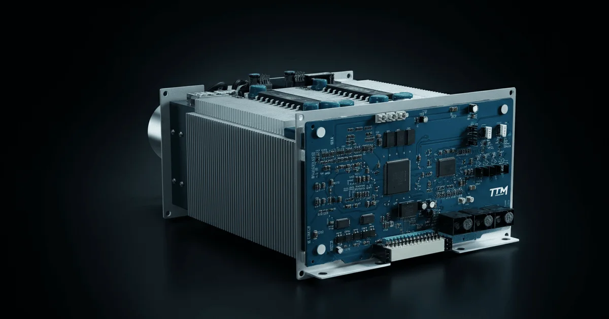
The TTM-1000 High-Intelligence Power Module: Architecture and Application in Marine Frequency Converters
Modern marine electric propulsion systems (EPS) significantly outperform traditional propulsion complexes due to their efficiency and flexibility. Key components of these systems are frequency converters (FCs), which, in turn, rely on intelligent power modules (IPMs). This article provides a detailed look at the architecture and functionality of the Russian high-intelligence power module (HIPM) TTM-1000, developed by the Ruselprom concern, and its application within a 1.67 MVA FC for EPS. This module is positioned as an analogue to foreign solutions, such as the SKS 140 from Semikron Danfoss, highlighting its significance in the context of technological sovereignty and the advancement of power electronics.
Detailed Structure of the TTM-1000-Based Frequency Converter
The 1.67 MVA frequency converter, utilizing the TTM-1000 as its core component, is a complex system designed for efficient control of marine electric propulsion. Its design incorporates several key components that ensure stable and safe operation. The main FC devices include: an input filter (IF), two TTM-1000 modules (one operating as an active voltage rectifier (AVR), the second as an autonomous voltage inverter (AVI)), a braking resistor unit (BRU), an FC control unit (FCCU), as well as various voltage and current sensors for monitoring the ship's electrical grid and internal parameters.
Auxiliary equipment includes power supplies, cooling and anti-condensation heating systems, as well as protection and switching devices that ensure the overall system's reliability. The IF features an LCL structure, comprising two three-phase inductors and three capacitors. One inductor is essential for AVR operation, while the second, together with the capacitors, forms a low-frequency filter, minimizing the FC's impact on the ship's grid.
TTM-1000 Module Architecture and Components
The TTM-1000 module is designed as a standardized transistor converter for various types of FCs. It is based on a three-phase bridge voltage converter, where each phase consists of four parallel-connected transistor modules, controlled by a common driver. The TTM-1000 comprises:
- Transistor Modules (TM1–TM12): These are IGBT modules featuring two IGBT transistors forming a half-bridge, two anti-parallel diodes, and a PTC thermistor.
- Capacitor Bank (CB): Composed of 18 film capacitors with polypropylene dielectric, ensuring low losses, low inductance, high permissible currents, and self-healing properties upon breakdown.
- Fast-acting Fuses (F1–F5): Designed to protect IGBT modules from short circuits.
- Transistor Drivers (TD1–TD3): Control, monitor, and protect the IGBT modules, ensuring their parallel operation and uniform current distribution.
- Sensors (VS, CS1–CS3): Measure DC link voltage and phase currents based on the Hall effect.
- Fans (F1, F2): Provide airflow to the capacitor bank to extend its service life.
Structurally, the TTM-1000 is housed in a metal frame and equipped with three liquid-cooled heat sinks, each mounting four IGBT modules and a driver. The terminals of the IGBT modules for each phase are connected to the DR-4T board for control and temperature monitoring, while the power terminals connect to the capacitor bank and, via special busbars, to fuses and current sensors.
Driver Functionality and Protection Systems
The drivers (TDs) play a critically important role in ensuring the reliability and efficiency of the TTM-1000. Each phase driver generates control pulses for four IGBT transistors, ensuring their synchronous operation and uniform current distribution. The drivers are also responsible for protecting the transistors from fault conditions and transmitting IGBT module temperature data to the FC control unit. Each driver consists of two boards: the main DR-4T board and the DR-M mezzanine board.
The DR-4T board contains passive electronic components necessary for controlling and monitoring IGBT transistors, including gate resistors and collector-emitter voltage sensing resistors. The DR-M board, based on a driver core from Power Integration, implements a comprehensive set of protection and service functions:
- Normalization and level conversion of input control signals.
- Filtering of short control signals.
- Protection against simultaneous turn-on of upper and lower half-bridge IGBT transistors (shoot-through protection).
- Generation of 'dead time' between transistor turn-off and turn-on.
- Protection of IGBT transistors from short circuits (SC) by desaturation detection.
- Protection against transient overvoltages and reverse power supply polarity.
- Protection against undervoltage of the power supply.
These functions ensure a high degree of reliability and longevity for the IGBT modules, minimizing the risk of failure under extreme operating conditions. Hall effect sensors (LEM or similar) are used for precise voltage and current measurement, forming the basis for the protection and control systems.
Technical Specifications and Auxiliary Systems
The TTM-1000 module boasts the following key technical specifications:
- Nominal Line Output Voltage: 690 V
- Nominal Phase Current: 1400 A
- Maximum Output Voltage Frequency: 100 Hz
- Maximum DC Link Voltage: 1300 V
- Nominal Power: 1670 kVA
- Maximum PWM Frequency: 5 kHz
- Input Power Factor (cos φ): from -1 to 1
- IGBT Module Cooling: Liquid
- Capacitor Bank Cooling: Forced Air
- Operating Temperature: -10 to +45 ºC
- Dimensions (W×H×D): not exceeding 250×1450×600 mm
- Weight: not exceeding 180 kg
The Braking Resistor Unit (BRU) consists of a powerful braking resistor and a transistor that switches it in relay or pulse-width modulation (PWM) modes to dissipate excess energy. The FC Control Unit (FCCU) features a block-modular design and includes three microcontroller-based control systems (MCCS): the AVR controller (AVRC), the AVI controller (AVIC), and the I/O signal controller (IOSC). It comprises modules for power supplies, microcontrollers, PWM outputs, voltage and current sensors, digital interfaces, discrete inputs/outputs, and temperature sensors.
The Voltage and Current Sensor Board (VCSB) receives signals from Hall effect sensors and temperature sensors, and also implements hardware protection for the FC against overvoltage, overcurrent, and overheating, independent of software. The Driver and Fan Interface Board (DFIB) ensures the transmission of optical control signals to the IGBT transistors and electrical error signals from the drivers to the FCCU.
Key Takeaways:
- The TTM-1000 is a Russian high-intelligence power module developed for marine frequency converters, serving as an analogue to foreign solutions.
- The module integrates IGBT transistors, drivers, a capacitor bank, and protection systems into a single enclosure, ensuring high power density and reliability.
- The TD driver system implements a comprehensive set of hardware protections, including short-circuit prevention, overvoltage protection, and control of transistor switching times.
- The TTM-1000-based FC utilizes combined cooling (liquid for IGBTs, forced air for capacitors) and a block-modular architecture for ease of maintenance and expansion.
- The application of the TTM-1000 in marine electric propulsion systems represents a significant step in the development of domestic power electronics for critical transportation applications.
— Editorial Team










No comments yet.