The use of MEMS gyroscopes and accelerometers to track the movements of the human body
Tracking the movements of the human body is a task that has been tackled with varying success for more than a thousand years. I once read a story about an ancient Greek speaker Demosthenes, who had a bad habit of lifting his shoulder to his ear if he was nervous. To get rid of this, during daily training, he hung his sword over his shoulder, which was very unpleasantly pricked if his shoulder was raised. As a result, the speaker became so famous that there is even a Wikipedia article about him.
Another good example many have seen in films about Chinese martial arts. For example, kung fu panda greatly spread his elbows while performing techniques. To track this moment, he put mugs in the armpit area. Burdock falls - the student receives a catch from the master. Surely some of us parents promised to fasten the stick to the back, if we stooped. True, these threats were never carried out and therefore acted not very convincingly.
Very often, motion tracking is required during sports training. For example, you can find patent US3820783 , which describes a training device that simultaneously guides the athlete and prevents him from moving incorrectly.

The installation scheme of the patent US 3820783
Motion Detection Using Video
In the mid-70s, systems appeared that processed video of movements made from several points. As a result, a mathematical model of this or that movement appeared. If you watch a video about how the film "The Lord of the Rings" was shot, you can see interesting episodes of the filming of Gollum's movements. In fact, a man in a special suit was moving, and then with the help of a smart mathematical apparatus and software, he turned out to be a pretty bald character.
Video recording of movements has obvious advantages, but since I want to describe an alternative solution in this article, I will allow myself to criticize a bit and bring down the disadvantages:
- video shooting must be done from several angles;
- often placing markers on the body;
- expensive hardware (cameras) is needed;
- need good computing power and an appropriate software product to convert video into a model of human movement;
- a person cannot move freely over long distances, otherwise he will inevitably go beyond the video zone;
- in addition to the measurement object, a team of specialists is needed, that is, it is unlikely that an ordinary user will be able to record the body movement on a morning run.
Motion measurement is a very useful thing, not only in sports. It is also used in industrial design - in the development of cars, conveyors, sewing machines and much more. Such systems already exist, for example, from Siemens - Jack ( Human Simulation and Ergonomics) How to find out if it will be convenient for the driver to press the power button on the air conditioner in the designed car? You can, of course, make a car, put a person in and check. But it’s much easier to put a virtual person in a virtual car. There is already a virtual car, since all modern drawing systems provide for the development of 3D models. It remains only to attach the movements of the human model to the movements of his real prototype. This can be done using the same video motion recording or using the method, which will be discussed below.
Smart clothes
In this article I want to tell you how wonderful it would be if you could measure movements without limiting yourself to the scope of the set. For example, if measurement functions were built into clothing. You walk, run, jump, and the clothes record everything and then reproduce your movements on the smartphone screen, give recommendations and suggest how to run and not injure your knees, sit and do not stoop, how to pedal the bike correctly and without injuries.
It turns out that science and technology already provide such opportunities. Of course, we are not talking about smart casual clothes yet, but there are already special suits consisting of wearable sensors that record body movements at a very good level. Such suits are made by XSENS.. They cost not cheaply, but as dozens of units of computer equipment appear in every family, microchips become cheaper and more and more intelligent portable systems become more and more. We are making great strides towards a brighter future. Without going deep into technical details I’ll try to tell you how the motion recording occurs, I will describe the operation and principle of operation of the main components of the motion measurement system based on electronic-mechanical sensors.
MEMS
As microelectronics develop, various miniature sensors appear. A separate group of such sensors is called MEMS - micro electromechanical sensors. To measure movements, acceleration sensors - accelerometers and angular velocity sensors - gyroscopes are used. The accelerometer is a miniature sensitive element that changes its properties under the action of acceleration. It can be a piezoelectric sensor or an element of variable capacitance - a capacitor with a movable lining. The piezoelectric sensor generates a small voltage on its electrodes, which can be measured and converted to acceleration. The situation is similar with the capacitance of a variable capacitor.
The MEMS gyroscope most often uses the action of the Coriolis force, which deflects the vibrating plate, in the design, the magnitude of the deviation is recorded and converted to angular velocity.
As we know from the course of physics and mathematics, any vector can be decomposed into the components of the vector. So, for example, acceleration and speed are decomposed into mutually perpendicular components: X, Y, Z. Sensitive MEMS elements measure acceleration and speed separately along each of these vectors.
It is important to note that now there are microcircuits that contain several MEMS sensors at once.
For example, the MEMS accelerometer chip measures acceleration along the three x, y, z axes at once. The same applies to gyroscope microcircuits, which can measure the angular velocity along all three axes at once. There are even microcircuits that simultaneously measure both acceleration and speed. Such sensors are called six-coordinate.
MEMS - controller
MEMS sensors are usually equipped with a built-in controller that calculates acceleration or angular velocity, provides digital filtering and chip configuration.
Data inside the controller is stored in special memory cells called registers. They are presented in integer format with a sign. The unit of measurement, as a rule, is g [gravitational acceleration - 9.8 m / s2] for accelerometers and rad / s [radians per second] for gyroscopes. A description of the data format, register addresses, units of measure, measuring ranges and other parameters are always given in the documentation for the corresponding chip.
The controller also provides MEMS sensor communication with the outside world through one of the common interfaces. Typically, this is SPI or I2C. SPI is an interface with two data lines and one clock line. I2C is an interface with one data line and one clock line. In principle, we only need to know that transmitting data from the MEMS sensor is easy and pleasant, for this there are standardized common interfaces and ready-made libraries.
A computer, tablet or smartphone does not have SPI or I2C interfaces available to the user, therefore, in order to connect the sensor to them, some other matching device is needed. This can be, for example, a microcontroller connected to a Bluetooth radio transmitter. The buffer microcontroller, as a rule, has the responsibility of preprocessing the data in order to reduce the load on the communication channel.
Generally speaking, the choice of a communication channel is a separate big task. Of course, this channel should preferably be wireless, but which wireless technology to choose? 2.4GHz communication standards, such as Bluetooth or WiFi, are good because they are supported by most user devices. But on the other hand, they limit the communication range due to the short wavelength. Of course, there are Bluetooth radio modules with a declared range of about a kilometer, but we will not flatter ourselves, because no one canceled the laws of physics, and such a range can only be obtained under conditions of direct visibility and a sufficient height of the sensors above the ground. It is important to determine the model of measurement and data processing. It’s one thing when all the calculations are done on a smartphone, which lies in a person’s pocket, and another thing, when the computer is tens of meters away on the table with the trainer / operator. It is more a matter of marketing and choosing the target audience of a complex of motion measurement. I only note that in any case, the task of transmitting data for the intended purpose can be solved and there are specialized hardware and software solutions for this.
Human body model
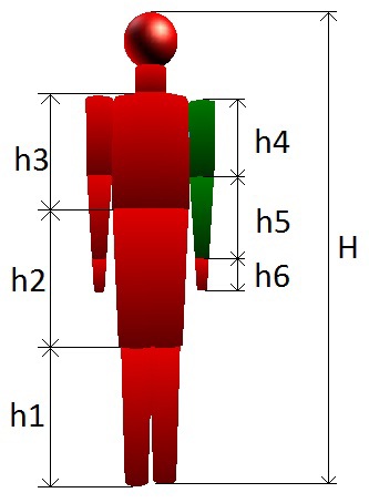
Let the data nevertheless reach its intended purpose and its processing begins. For calculations and visualization of movements, we just need a mathematical model of the human body. Such a model should certainly take into account the different lengths of the arms, legs, waist, chest, that is, various anthropometric characteristics of people. Perhaps such a model should also take into account the internal structure of the body. The more complex the model, the more difficult, expensive and longer its creation. I personally believe that the model should contain only those elements that you can put on a sensitive element. That is, if we are talking about the hand, then it is advisable to make its model from the following parts:
- shoulder;
- forearm;
- brush;
- fingers;
Building a model with all the bones, muscles and tendons inappropriate. A cone can act as the simplest model of one part of the body. This is a simple geometric figure that can be easily implemented in any graphical environment and which does not require a lot of resources, which is especially true for mobile platforms. Actually, the volumetric shape of the cone is used to visualize the model, and the vector, which coincides with the longitudinal axis of symmetry, is used for various calculations. Different lengths of the lower and upper circles of the cone easily simulate differences in diameters, for example, the hips above and around the knee.
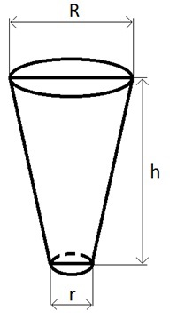
Cone, as an element of the human body model.
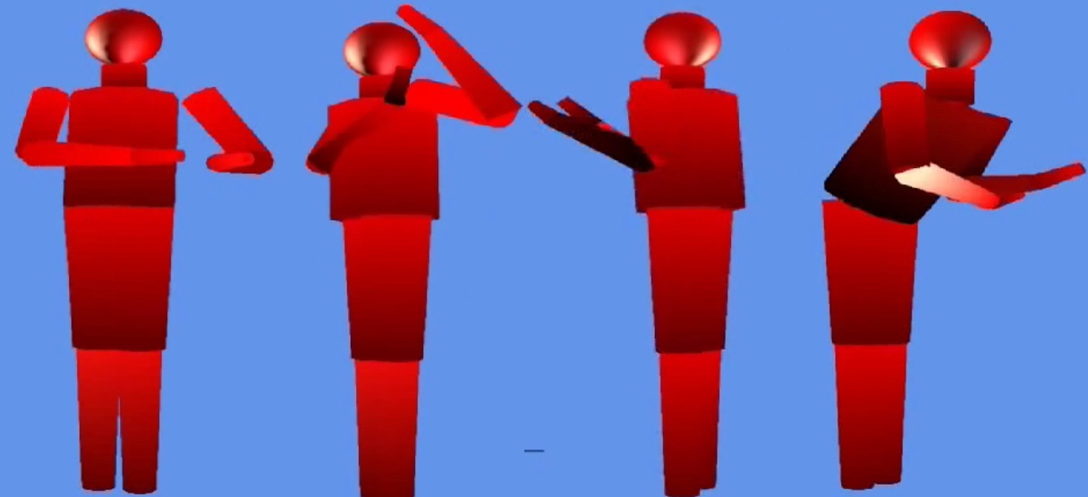
A complete model of the human body composed of cones.
Agree that the model looks pretty recognizable. This model was built in the Microsoft XNA environment. Primitives3D libraries found on the Internet were used to draw the cone . To arrange the elements of the model, the mathematical apparatus of matrix calculations of the XNA environment is used.
A bit about computing
The space in which the model is located is called world space. In order to move model elements in world space, it is necessary to compose displacement matrices; in order to rotate, necessary rotation matrices. Generally speaking, these are the same matrices, only for different purposes they use different cells.
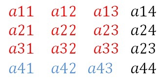
Matrix structure in XNA environment
Elements marked in red are responsible for rotation, elements highlighted in blue for movement, and black elements are needed to comply with 4x4 dimensions. To create a displacement matrix, use the method:
Matrix.CreateTranslation(vector3)Which as a parameter takes the radius vector of the desired position of the point. To place all the elements of the body, it is necessary to compose a displacement matrix for each of them, let's call such a matrix fBaseWorldi.
Everything related to the movement of 3D models is well known to computer game developers and other specialists working in the field of computer 3D graphics.
We will move on to the most interesting, namely, how to relate the measurements of angular velocity and acceleration with the position of the model on the screen. The position of the body in space can be specified using Euler angles, displacement and rotation matrices, or using quaternions. Many copies are broken in disputes over which method to choose. I use the quaternion position representation. It is easy to move from one method to another using well-known mathematical transformations.
A quaternion is a set of four numbers defining in space an axis around which you want to rotate the body and the angle of rotation. The quaternion is written in the form:
q = [W, X, Y, Z],
where W is the cosine of the half-angle of rotation; X, Y, Z - coordinates of the axis of rotation.
A quaternion is preferable to rotation matrices, since the matrix contains 16 numbers, and the quaternion only 4, which obviously saves data transfer time and does not load the communication channel so much.
An attentive reader can rightly object that a quaternion can describe only rotational motion, but what about the translational? The fact is that the proposed method is designed to register movements without reference to the surrounding area. And all human movements can be built due to rotations alone.
Indeed, our body is practically not subject to pure (without rotation) stretching and compression. For example, to linearly move the brush forward or backward, up or down, you will have to rotate the forearm in the elbow joint or shoulder in the shoulder.
The only thing left is to convert the acceleration and angular velocity into quaternions. The mathematical apparatus that produces such transformations is the holy of holies of firms producing motion measurement systems. This device is generally known, you can even find source codes on the Internet ( Open source IMU and AHRS algorithms), but as usual all the difficulties lie in the details. Therefore, do not be surprised if the motion measurements contain position errors. This is due to errors in the readings of the sensors, which are integrated and significantly affect the result. Also, errors in the location of sensors on the human body contribute their share of inaccuracies. A good solution is provided by the manufacturer of MEMS chips Invensense, they produce microcircuits into which they can load the supplied library that performs calculations. In early versions, the library was a code written in C that ran on a third-party microcontroller. Now the library is an array of hexadecimal numbers that need to be loaded into the MEMS chip after power is supplied to it. A similar solution is provided by other companies, such as Microchip .
After we calculated the position of the body part and expressed it in the form of a quaternion, it is necessary to draw up a general model from the indications relating to individual parts of the body. This is where the XNA environment and Primitives3D code come in handy. The Primitives3D library used to move or rotate uses the data in a matrix representation. Therefore, to convert the quaternions received from sensors, you must use the built-in function in XNA:
Matrix.CreateFromQuaternion(qi)where qi is the quaternion from the sensor.
Then it is necessary to transfer the rotated part of the body from the origin to the corresponding point where it should be located, for example the forearm is “attached” to the elbow. Although you have already seen in the picture a completely “assembled” body, so that it is always in the correct position after the arrival of each new quaternion, the body position must be re-calculated. This is due to the fact that the library for calculating quaternions produces a quaternion, which connects the position of the body at zero time with the current moment. To carry out the transfer of a part of the body you just need to multiply two matrices:
Matrix.CreateFromQuaternion(qi)* fBaseWorldiThe fBaseWorldi matrix is constantly being adjusted, because if the shoulder has moved, then the elbow will also move accordingly. Therefore, in the program, after the arrival of the quaternion for any part of the body, the matrices fBaseWorldi should be calculated for all other parts of the body associated with it. <
The video shows the human movement obtained using seven sensors, three sensors on each arm and one on the torso in the lower back.
Now that we have obtained a record of body movements, it is possible to make calculations of various interesting quantities on the basis of these data. For example, to help Demosthenes and attach a sensor to his shoulder that will monitor the correct position and give out some signal when deviating from this position, just as if you launch the application on a smartphone, and place several sensors on the back of a child, this will help him control your posture. And how many different useful applications for MEMS sensors.
Conclusion
In this article, I tried to review the main points associated with the use of MEMS sensors in relation to measuring the movements of the human body. Of course, many of the issues mentioned here require a more detailed explanation, in addition, I did not mention some nuances specifically so as not to clutter up the article with details.