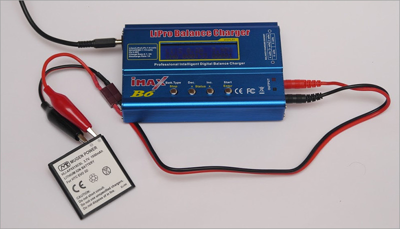
We pump smart charging Imax B6
Truly they say: laziness is the engine of progress! So for me, my head thrilled, to automate the process of measuring and training acid batteries. After all, who, in their right mind, will, in our age of smart microcircuits, pore over a battery with multimeters and a stopwatch? Surely, many people know the "people's" charger Imax B6. On a habr there is an article about him (and even not one). Below I will write what I did to her and why.
In the beginning, my goal was to increase the discharge power in order to measure my batteries for an uninterruptible power supply and, in the future, train them without risking premature old age (me, not batteries). I drove the device disassembled.
Inside, it is generously packed with many differential amplifiers, a multiplexer, a buck-boost regulator with high efficiency, it has a good case, and on the network you can find open source code very goodfirmware. With a charging current of up to 5 amperes, they can even charge car batteries at 50A / h (current 0.1C). With all this, with this wealth, as current sensors, here we use the usual 1 W resistors, which, among other things, operate at the limit of their power, which means that their resistance floats significantly under load. Can you trust such a measuring device? After blowing and touching these “sensors” with my hands, my doubts are gone - I want to remake them into manganin shunts!
Manganin (there is also constantan) is a special alloy for shunts, which practically do not change their resistance from heating. But its resistance is an order of magnitude less than the replaceable resistors. Also, in the device circuit, operational amplifiers are used to amplify the voltage from the sensor to readable values by the microcontroller (I believe the upper limit of digitization is the reference voltage with TL431, about 2,495 volts).
My refinement is to solder shunts instead of resistors, and compensate for the difference in levels by changing the gain of operational amplifiers to LM2904: DA2: 1 and DA1: 1 (see diagram).
For alteration, we need: the device itself is the original (I describe the alteration of the original), manganin shunts (I took from Chinese multimeters), an ISP programmer, cheali-charger firmware (for calibration), Atmel Studio for its assembly (optional), eXtreme Burner AVR for its firmware and experiencein creating bricks for successful atmega firmware (All links are at the end of the article).
And also: the ability to solder SMD and an irresistible desire to restore justice.
I have never studied the development of circuits and, in general, amateur radio, so making such changes to a working device like that on the go waslazyscary. And here multisim came to the rescue! It is possible, without touching the soldering iron: to realize the idea, debug it, fix errors and understand whether it will even work. In this example, I modeled a piece of the circuit, with an operational amplifier, for a circuit providing a charge mode:

Resistor R77 creates negative feedback. Together with R70, they form a divider that sets the gain, which can be calculated something like this (R77 + R70) / R70 = gain. My shunt turned out to be about 6.5 mΩ, which at a current of 5 A will make a voltage drop of 32.5 mV, and we need to get 1.96 V to match the logic of the circuit and the expectations of its developer. I took 1 kΩ and 57 kΩ resistors as R70 and R77 respectively. According to the simulator, 1.88 volts were obtained at the output, which is quite acceptable. I also threw out the resistors R55 and R7, as they reduce linearity, they are not used in the photo (maybe this is an error), and I connected the shunt with dedicated wires to the bottom of R70, C18, and the top of the shunt directly to the "+" input of the op-amp.

Excess tracks are trimmed, including on the back of the board. It is important to solder the wires well so that they do not fall off, over time, from the shunt or the board, because not only the ADC of the microcontroller is fed from this sensor, but also the feedback on the current of the pulse regulator, which, if the signal disappears, can go into maximum mode and ditch yourself.
The circuit for the discharge mode is not fundamentally different, but since I put the VT7 field on the radiator and increase the discharge power to the limit of the field (94 W on the datasheet), I would like to set the maximum discharge current in a larger way.
As a result, I received: R50 - a shunt of 5.7 mOhm, R8 and R14 - 430 Ohm and 22 kOhm, respectively, which gives the required 1.5 volts at the output when the current through the shunt is 5 A. However, I experimented with a large current - maximum 5.555 A was released, so the limit to 5.5 A was sewn into the firmware (in the file "cheali-charger \ src \ hardware \ atmega32 \ targets \ imaxB6-original \ HardwareConfig.h").
A problem got out along the way - the charger refused to admit that it was calibrated (i discharge). This is due to the fact that the verification does not use the MAX_DISCHARGE_I macro definition in the "HardwareConfig.h" file, but the second calibration point for checking the first (the points are described in the "GlobalConfig.h" file). I did not go into the intricacies of the code and just cut out this check in the checkAll () function in the “Calibrate.cpp” file.
As a result of the alterations, a device was obtained that ensured an acceptable linearity of measurements in the range from 100mA to 5A and which could be called measuring, if not one but: since I left a powerful discharge pole in the case (despite improved cooling), the board heats up from him, anyway, introduces a distortion into the measurement result, and the measurements “float” a little towards understatement ... I’m not sure who exactly is to blame for this: error amplifier or microcontroller ADC. In any case, IMHO, it is worth taking this fieldman outside the enclosure and providing it with sufficient cooling (up to 94W or replacing it with another suitable N-channel).
I did not want to write about it, but they forced me.
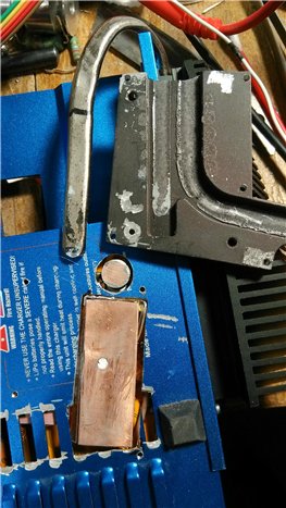
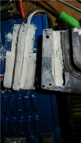
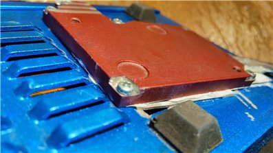
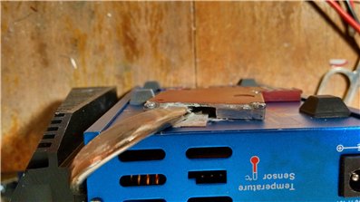
Polevik VT7, in a new place, is glued to hot-melt adhesive, and its heat sink is soldered to a copper plate:

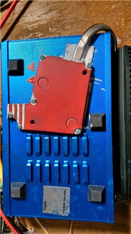
I decided to make cooling out of an unnecessary radiator on the heat pipe from the motherboard. The photo shows a suitable pressure plate and transistor area, along the perimeter of which an insulating plastic is laid - just in case. A heel of soldering iron tip is soldered directly to the board, to the common wire - it will play the role of additional heat sink from the converter: The assembled design will not prevent the device from standing on its legs: Ready for firmware:

I experienced this alteration in passive cooling mode: a discharge of 20 minutes of a 6-volt Pb-battery with a maximum current of 5.5A. Power flashed 30 ... 31W. The temperature on the heat pipe, through a thermocouple, reached 91 ° C, the case also became hot and, at some point, the screen began to turn purple. Of course, I immediately interrupted the test. The screen could not bounce back for a long time, but then it was released.
Now it is already obvious that a remote load unit, with a detachable connection, would be the best solution: there are no restrictions on the size of the radiator and fan, and the charging itself would be more compact and light (no discharge is needed in the field).
I hope that this article will help beginners to be bolder in experiments on helpless pieces of iron.
Comments and additions are welcome.
Warning: the described modifications, if misused, can damage the charging components, turn it into an irreversible “brick”, as well as reduce the reliability of the device and create a risk of fire. The author declines responsibility for possible damage, including for wasted time.
Alternative firmware cheali-charger: https://github.com/stawel/cheali-charger (Her review on youtube: one , two ).
To compile the firmware: Atmel Studio and CMake Flasher
program: eXtreme Burner AVR
ISP programmer: USBASP Programmer for ATMEL
Accuracy
In the beginning, my goal was to increase the discharge power in order to measure my batteries for an uninterruptible power supply and, in the future, train them without risking premature old age (me, not batteries). I drove the device disassembled.
Inside, it is generously packed with many differential amplifiers, a multiplexer, a buck-boost regulator with high efficiency, it has a good case, and on the network you can find open source code very goodfirmware. With a charging current of up to 5 amperes, they can even charge car batteries at 50A / h (current 0.1C). With all this, with this wealth, as current sensors, here we use the usual 1 W resistors, which, among other things, operate at the limit of their power, which means that their resistance floats significantly under load. Can you trust such a measuring device? After blowing and touching these “sensors” with my hands, my doubts are gone - I want to remake them into manganin shunts!
Manganin (there is also constantan) is a special alloy for shunts, which practically do not change their resistance from heating. But its resistance is an order of magnitude less than the replaceable resistors. Also, in the device circuit, operational amplifiers are used to amplify the voltage from the sensor to readable values by the microcontroller (I believe the upper limit of digitization is the reference voltage with TL431, about 2,495 volts).
My refinement is to solder shunts instead of resistors, and compensate for the difference in levels by changing the gain of operational amplifiers to LM2904: DA2: 1 and DA1: 1 (see diagram).
Scheme
For alteration, we need: the device itself is the original (I describe the alteration of the original), manganin shunts (I took from Chinese multimeters), an ISP programmer, cheali-charger firmware (for calibration), Atmel Studio for its assembly (optional), eXtreme Burner AVR for its firmware and experience
And also: the ability to solder SMD and an irresistible desire to restore justice.
I have never studied the development of circuits and, in general, amateur radio, so making such changes to a working device like that on the go was
Resistor R77 creates negative feedback. Together with R70, they form a divider that sets the gain, which can be calculated something like this (R77 + R70) / R70 = gain. My shunt turned out to be about 6.5 mΩ, which at a current of 5 A will make a voltage drop of 32.5 mV, and we need to get 1.96 V to match the logic of the circuit and the expectations of its developer. I took 1 kΩ and 57 kΩ resistors as R70 and R77 respectively. According to the simulator, 1.88 volts were obtained at the output, which is quite acceptable. I also threw out the resistors R55 and R7, as they reduce linearity, they are not used in the photo (maybe this is an error), and I connected the shunt with dedicated wires to the bottom of R70, C18, and the top of the shunt directly to the "+" input of the op-amp.
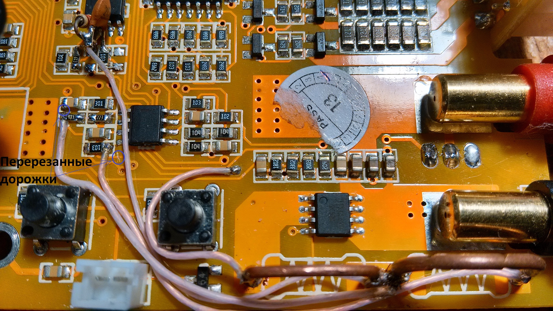
Excess tracks are trimmed, including on the back of the board. It is important to solder the wires well so that they do not fall off, over time, from the shunt or the board, because not only the ADC of the microcontroller is fed from this sensor, but also the feedback on the current of the pulse regulator, which, if the signal disappears, can go into maximum mode and ditch yourself.
The circuit for the discharge mode is not fundamentally different, but since I put the VT7 field on the radiator and increase the discharge power to the limit of the field (94 W on the datasheet), I would like to set the maximum discharge current in a larger way.
As a result, I received: R50 - a shunt of 5.7 mOhm, R8 and R14 - 430 Ohm and 22 kOhm, respectively, which gives the required 1.5 volts at the output when the current through the shunt is 5 A. However, I experimented with a large current - maximum 5.555 A was released, so the limit to 5.5 A was sewn into the firmware (in the file "cheali-charger \ src \ hardware \ atmega32 \ targets \ imaxB6-original \ HardwareConfig.h").
A problem got out along the way - the charger refused to admit that it was calibrated (i discharge). This is due to the fact that the verification does not use the MAX_DISCHARGE_I macro definition in the "HardwareConfig.h" file, but the second calibration point for checking the first (the points are described in the "GlobalConfig.h" file). I did not go into the intricacies of the code and just cut out this check in the checkAll () function in the “Calibrate.cpp” file.
As a result of the alterations, a device was obtained that ensured an acceptable linearity of measurements in the range from 100mA to 5A and which could be called measuring, if not one but: since I left a powerful discharge pole in the case (despite improved cooling), the board heats up from him, anyway, introduces a distortion into the measurement result, and the measurements “float” a little towards understatement ... I’m not sure who exactly is to blame for this: error amplifier or microcontroller ADC. In any case, IMHO, it is worth taking this fieldman outside the enclosure and providing it with sufficient cooling (up to 94W or replacing it with another suitable N-channel).
Firmware
I did not want to write about it, but they forced me.
- Download and install the necessary materials (links at the end of the article).
- We solder the jumper on the programmer and set the jumper JP3 - this will switch the interface to slow mode. Until I set the jumper, I had problems with the firmware.
- We connect the programmer to the device, and the programmer to the computer (the picture below is for the original device! The clone connects differently):
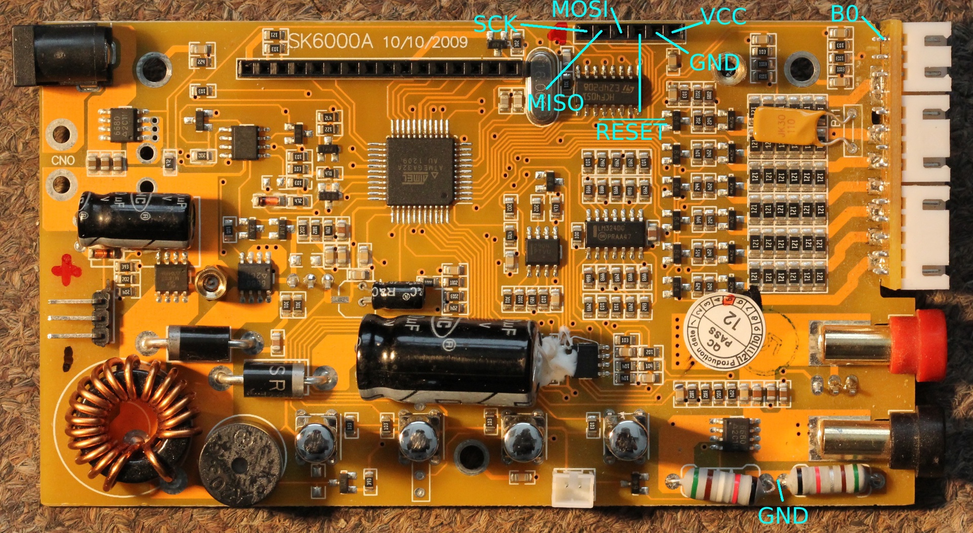
- In the eXtreme Burner program, select our chip (Chip-> ATmega32 menu), and then try to read everything (Read All). If everything worked out, the original firmware and EEPROM can be saved somewhere, just in case.
- Now let's try to compile our firmware (this step is not necessary, you can take the finished one from the “cheali-charger \ hex \ cheali-charger-imaxB6-original-0.33.hex” folder, in this case, go to step 6).
In general, how and what can be done is often written in the accompanying documentation, for example, about the assembly - in the building.md file.
In this case, the order is:- install Atmel Studio and cmake
- run “Atmel Studio Command Prompt” and go to the folder with
cheali-charger.
That is, for example: cd s: \ cheali-charger - run: s: \ cheali-charger> cmake. -G "Unix
Makefiles" - run: s: \ cheali-charger> make
- The firmware file should be created here:
"s: \ cheali-charger \ src \ hardware \ atmega32 \ targets \ imaxB6-original \ cheali-charger * .hex"
- Download our firmware in eXtreme Burner, then click Write-> Flash. God forbid to sew by mistake "everything", for example: the wrong fuses that are on the 3rd tab - in this case, you can lose access for further firmware via ISP, or maybe through other interfaces. It is possible to revive the resulting brick only on a high-voltage parallel programmer. Just in case, the correct fuses: low = 3F, high = C5.
- Calibration She will need a li-ion battery of at least 2 elements. The calibration procedure can be found in "README.md". By moving it to the side along the balanced connector, you can calibrate all 6 inputs, while the first 2 can be calibrated separately (more precisely) in the expert calibration menu, it is written about it in “calibration_expert.md”.
A little about my refinement cooling
Polevik VT7, in a new place, is glued to hot-melt adhesive, and its heat sink is soldered to a copper plate:
I decided to make cooling out of an unnecessary radiator on the heat pipe from the motherboard. The photo shows a suitable pressure plate and transistor area, along the perimeter of which an insulating plastic is laid - just in case. A heel of soldering iron tip is soldered directly to the board, to the common wire - it will play the role of additional heat sink from the converter: The assembled design will not prevent the device from standing on its legs: Ready for firmware:


I experienced this alteration in passive cooling mode: a discharge of 20 minutes of a 6-volt Pb-battery with a maximum current of 5.5A. Power flashed 30 ... 31W. The temperature on the heat pipe, through a thermocouple, reached 91 ° C, the case also became hot and, at some point, the screen began to turn purple. Of course, I immediately interrupted the test. The screen could not bounce back for a long time, but then it was released.
Now it is already obvious that a remote load unit, with a detachable connection, would be the best solution: there are no restrictions on the size of the radiator and fan, and the charging itself would be more compact and light (no discharge is needed in the field).
I hope that this article will help beginners to be bolder in experiments on helpless pieces of iron.
Comments and additions are welcome.
Warning: the described modifications, if misused, can damage the charging components, turn it into an irreversible “brick”, as well as reduce the reliability of the device and create a risk of fire. The author declines responsibility for possible damage, including for wasted time.
References
Alternative firmware cheali-charger: https://github.com/stawel/cheali-charger (Her review on youtube: one , two ).
To compile the firmware: Atmel Studio and CMake Flasher
program: eXtreme Burner AVR
ISP programmer: USBASP Programmer for ATMEL