PIC16F1503. Wheelbarrow for pumping - 1. Sound
- Tutorial
I think every parent has a moment when he discovers a child with something in the store at the checkout , and the child claims that it is this something that is very important for the whole world on earth and for him in particular. So it happened to me again. Immediately evaluating the cost of this nothing , the parent toad waved his hand and decided that once we live and still not make all the money. Reason appreciated the speed of dying of this nothing and also gave the go-ahead.
As a result, the children's fleet was replenished with such a miracle of Chinese engineering. Jeep, with a "chandelier" and a winch!

The miracle was able to blink “chandelier” and “headlights” and make three recorded sounds loudly. According to all the canons, the machine quickly "died" and was brought in for repair. I refused to take the car for repair, explaining the refusal with unwashed hands and an undernourished dinner. Plus, the Chinese somehow managed to squeeze out a couple of extra decibels from this machine at a frequency resonating with my skull (already my teeth ached), so I did not smile at all to re-experience the same sensations.
As a result of long negotiations, it was decided that a simple change of batteries is no longer fashionable. After all, all real drivers tune their cars in special studios, after which they drive cars that no one has. So I took the car to the studio "All My" for tuning ...
What is the first thing to do? That's right, to evaluate how much work fell on us. We disassemble the car.

Inside there are three LEDs (blue, bright, cheap), a tweeter and an unknown Chinese snot class microcontroller. All this is powered by 3 LR4 batteries (capacity around 20mAh), so it is not surprising that the car died so quickly. All this splendor is triggered by a button, which, in the best traditions of the Chinese automobile industry, seizes and bites.
In general, everything needs to be changed here. Well, or almost everything. For what?
Of course, I wouldn’t mind sticking the STM32F4 inside, but the evaluation board doesn’t get inside, but put it under itthe circuit board is frankly lazy. Rummaging through the drawers, I found a demo board on the PIC16F1503. Up to 16 megahertz, 3 kilobytes of flash and as many as 128 bytes of memory. The most it is for the machine!
If you want to repeat my exercises, then you need to look for the words PIC-H1503 (this is the microcontroller itself) and PIC-KIT3 (this is the programmer) from Olimex. It will also be necessary to download and install MPLAB X Ide and XC8 from the microlab website. Unlike OT, Windows, Linux and OS X are supported.
Where do I need to start tuning? That's right, let's start like everything with sound. We don’t need louder, we need something to be heard “in the police” and not loudly.
We take out the squeaker from the machine and try to understand what it is. Not finding any identification marks, we cling to an ohmmeter. An ohmmeter shows 15 ohms. It means a microdynamic speaker: if an ohmmeter showed a “cliff”, then this is a piezo tweeter.
It makes no sense to connect the speaker directly to the microprocessor leg (15 ohms at 3 volts will give a current of 200 mA, which the microcontroller, who is 20 by the eyes, will obviously not like), so we make a simple circuit on the first NPN transistor that comes across.
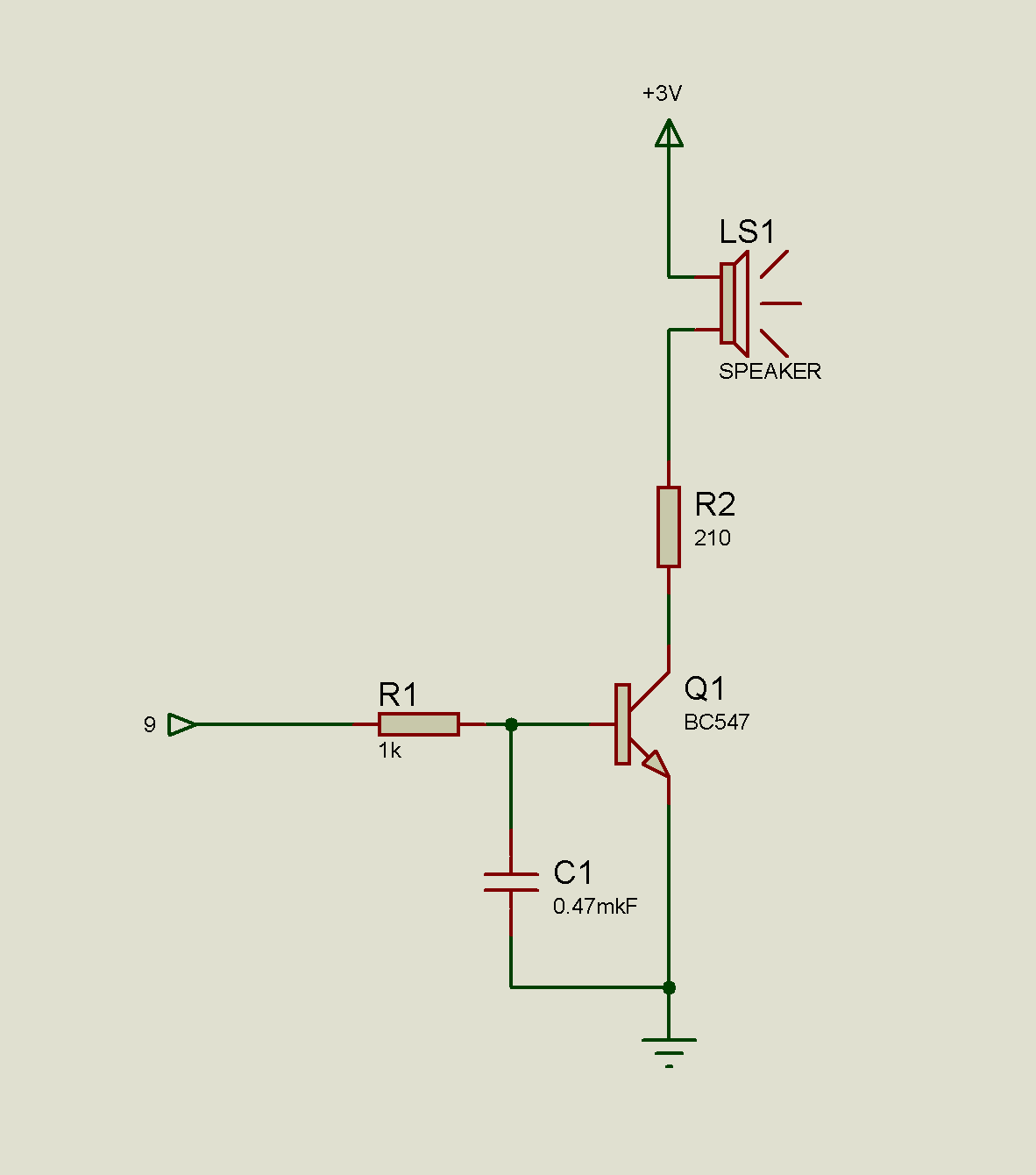
Denominations are practically not important. Plus or minus from the circuit will not bring almost any changes. Why a capacitor in the circuit, I will explain later (in principle, it can be plugged in parallel with the transistor). The input is connected to the 9th leg of the microcontroller.
Now it remains to understand how we can extract the sound. From the school physics course, we know that sound is air vibrations. And the speaker translates the vibrations of electricity into vibrations of air. So we need to shake the speaker. But the speaker is connected directly to the microcontroller, and he can only give out "1" (there is a leg) and "0" (there is nothing). Yes, even (even? Yes, this is rare) this microcontroller has as much as a 5-bit DAC (audiophiles drag themselves from single-bit ones, if anything. Smail), but this is not sports.
The physicist saves us again: even if you apply “1” to the speaker, the magnet will not immediately pull up the diffuser, just like after “0” it will not release it instantly.
The easiest thing is to write code like this
If pauses are counted in milliseconds, then in dynamics we will get a “squeak” at 500Hz. And changing the duration of the pauses, you can get quite a decent sound. What is the problem? The problem is that we will need to constantly be distracted by "leg jerking."
But in any decent microcontroller there is such a thing as PWM, it is also PWM (what is it? It is easily looked for in the same Wikipedia, with pictures and long explanations). There is she at the peak. Open MPLAB, create a new project, and using Code Configurator (Tools-Embedded menu. You may need to first install it in Plugins) add a new PWM.
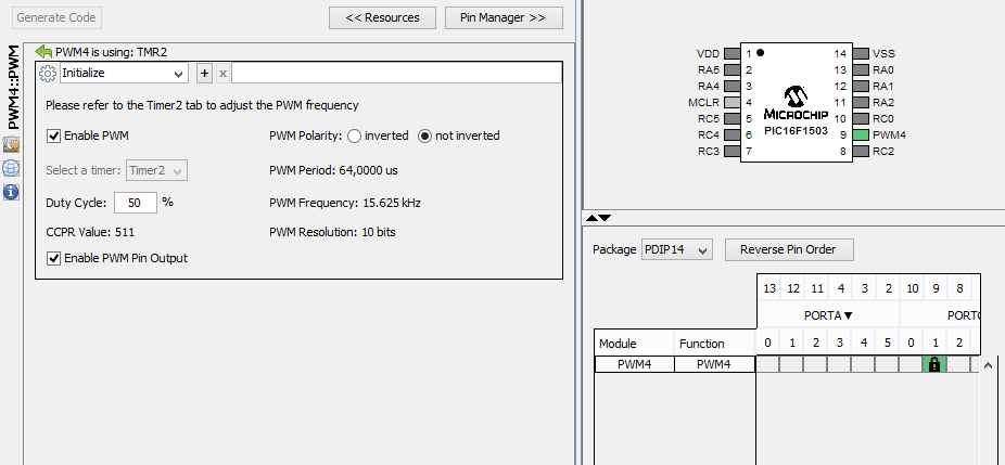
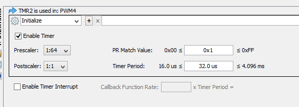
I took the PWM4 solely because of the convenience of the foot. Since PWM at its peak cannot do without a timer, let's look at it.
Since nothing is clear yet, just click "Generate Code" and try to run the result. As usual, nothing should happen - there is no program. If you got an error about VDD, then in Run-Project Configuration-PICKit3-Power you need to check the box next to the Power target Circuit. It is just possible to program the boards “at work”, and the current from the programmer is not always enough to power the circuit.
We dial the first code. Everything is done in main.c, there I divided the blocks with comments.
We upload and connect the oscilloscope with one input to the output of the microcontroller (blue line) and the other to the speaker (red).
So what do we see? The blue line is the result of the PWM. Fill from 0 to 100% and jump again to zero. But the red line somewhere in the middle of the filling is vaguely similar to a sine wave. Frankly, this remoteness is obtained by attaching a 0.47 uF capacitor parallel to the transistor, for a beautiful gif. The real picture can be seen below.
We remove the capacitor.
See the peaks on red? This “reverse” speaker works like a generator and easily throws a whole volt when powered by 3x. In principle, subject to certain conditions, it is easy to burn the circuit. But here, these peaks do not bother anyone, so whether or not to install a Conder is up to you. I set for the sake of beauty.
We will put it again. It already was, but this picture is static.

Change to 0.1 μf. Just to compare and display the effect of capacitance on sound :)
In principle, we already got a squeak of 15 kilohertz, but who needs it, except for mosquitoes? So you need to twist the frequency. The frequency of the PWM depends on the timer, and how often the timer will “tick” depends on the counter that is set each time the timer starts.
That is, the algorithm of the timer looks something like this
- Start the timer.
- The timer ticked and decreased the counter.
- The counter is at zero? If not, then tick again. If so, generate an interrupt.
Interrupt handler:
- OH! Timer ticked!
- Reset timer again
And now the start of the PWM is just with us hooked to the timer interrupt. And we can twist both the frequency of the "tick input" (prescaler in the settings) and the counter value.
Change the code (it's stage2)

We look at the beautiful red line and see that we get something distant to a sinusoid, and changing in frequency. Yes, and the ear confirms. What we need!
Why am I changing the PWM filling, I propose to think on my own. But in principle, if you mentally continue the graph and slow down the change in one parameter, then everything becomes clear. Particularly advanced ones can see a similar picture in some emulator, for example proteus.
Now we’ll determine what frequency range we got. We
beat count at 255
And now we set at 10

Pay attention to the upper right corner, where the grid step is indicated. “By eye” I got a range of about 300-5000Hz. Quite. And the skull "ride" will not.Perfectionists can use a frequency meter, or calculate the real value from the clock frequency and prescalers.
But then I had problems. I don’t have any understanding of how it should sound. Roughly speaking, in Chukchi music the reader, but not the writer.
I hardly found in half what frequencies corresponded to which notes, I found some kind of musical notation “a Christmas tree was born in the forest” ... I
calculated the delays, wrote
Compiled, launched. No, the melody is guessed without problems, but it's not like that. By selecting resistors and capacitors, I achieved an “almost sinusoid saw” at the output, but the ear hears the difference.
In the end, I stopped at the usual two-tone signal: “high-low”. The classic policeman “wow-wow”, known to everyone from Hollywood films, did not work out for me. And Google in response to the "police sirene tones code programm example" gives anything, just not what you need.
Help, please? In what sequence does the scumbling go there?
In principle, we have already come to the point of taking and reproducing the usual wav as the next step. That is, do not suffer with tones and other things. Just record the sound, translate it into a digestible form and play. As different ScreamTrackers did at the time.
There is only one problem: half a second of sound in PCM format, mono, with 8KHz sampling, takes about a kilobyte. And I have only three and a half kilobytes. It won’t work. But you can familiarize yourself with the principles and examples simply by entering Google “pic pcm sound”. And right from the first link will be the source and the programs themselves.
Therefore, we are comforted by the fact that we will have a real, “warm tube sound from those times”, for which the programmer does not need attention: he said what frequency to stick and went about his own business, and there the pieces of iron will do everything themselves.
But sound is half the battle. Good light is also a hallmark of this tuning :) But this is a bit later.
As usual, a finished project for MPLAB with all the pieces can be picked up here.
As a result, the children's fleet was replenished with such a miracle of Chinese engineering. Jeep, with a "chandelier" and a winch!
The miracle was able to blink “chandelier” and “headlights” and make three recorded sounds loudly. According to all the canons, the machine quickly "died" and was brought in for repair. I refused to take the car for repair, explaining the refusal with unwashed hands and an undernourished dinner. Plus, the Chinese somehow managed to squeeze out a couple of extra decibels from this machine at a frequency resonating with my skull (already my teeth ached), so I did not smile at all to re-experience the same sensations.
As a result of long negotiations, it was decided that a simple change of batteries is no longer fashionable. After all, all real drivers tune their cars in special studios, after which they drive cars that no one has. So I took the car to the studio "All My" for tuning ...
What is the first thing to do? That's right, to evaluate how much work fell on us. We disassemble the car.
Inside there are three LEDs (blue, bright, cheap), a tweeter and an unknown Chinese snot class microcontroller. All this is powered by 3 LR4 batteries (capacity around 20mAh), so it is not surprising that the car died so quickly. All this splendor is triggered by a button, which, in the best traditions of the Chinese automobile industry, seizes and bites.
In general, everything needs to be changed here. Well, or almost everything. For what?
Of course, I wouldn’t mind sticking the STM32F4 inside, but the evaluation board doesn’t get inside, but put it under itthe circuit board is frankly lazy. Rummaging through the drawers, I found a demo board on the PIC16F1503. Up to 16 megahertz, 3 kilobytes of flash and as many as 128 bytes of memory. The most it is for the machine!
If you want to repeat my exercises, then you need to look for the words PIC-H1503 (this is the microcontroller itself) and PIC-KIT3 (this is the programmer) from Olimex. It will also be necessary to download and install MPLAB X Ide and XC8 from the microlab website. Unlike OT, Windows, Linux and OS X are supported.
Where do I need to start tuning? That's right, let's start like everything with sound. We don’t need louder, we need something to be heard “in the police” and not loudly.
We take out the squeaker from the machine and try to understand what it is. Not finding any identification marks, we cling to an ohmmeter. An ohmmeter shows 15 ohms. It means a microdynamic speaker: if an ohmmeter showed a “cliff”, then this is a piezo tweeter.
It makes no sense to connect the speaker directly to the microprocessor leg (15 ohms at 3 volts will give a current of 200 mA, which the microcontroller, who is 20 by the eyes, will obviously not like), so we make a simple circuit on the first NPN transistor that comes across.
Denominations are practically not important. Plus or minus from the circuit will not bring almost any changes. Why a capacitor in the circuit, I will explain later (in principle, it can be plugged in parallel with the transistor). The input is connected to the 9th leg of the microcontroller.
Now it remains to understand how we can extract the sound. From the school physics course, we know that sound is air vibrations. And the speaker translates the vibrations of electricity into vibrations of air. So we need to shake the speaker. But the speaker is connected directly to the microcontroller, and he can only give out "1" (there is a leg) and "0" (there is nothing). Yes, even (even? Yes, this is rare) this microcontroller has as much as a 5-bit DAC (audiophiles drag themselves from single-bit ones, if anything. Smail), but this is not sports.
The physicist saves us again: even if you apply “1” to the speaker, the magnet will not immediately pull up the diffuser, just like after “0” it will not release it instantly.
The easiest thing is to write code like this
while(1)
{
  dinamikON();
  pause(1);
  dinamikOFF();
  pause(1);
}
If pauses are counted in milliseconds, then in dynamics we will get a “squeak” at 500Hz. And changing the duration of the pauses, you can get quite a decent sound. What is the problem? The problem is that we will need to constantly be distracted by "leg jerking."
But in any decent microcontroller there is such a thing as PWM, it is also PWM (what is it? It is easily looked for in the same Wikipedia, with pictures and long explanations). There is she at the peak. Open MPLAB, create a new project, and using Code Configurator (Tools-Embedded menu. You may need to first install it in Plugins) add a new PWM.
I took the PWM4 solely because of the convenience of the foot. Since PWM at its peak cannot do without a timer, let's look at it.
Since nothing is clear yet, just click "Generate Code" and try to run the result. As usual, nothing should happen - there is no program. If you got an error about VDD, then in Run-Project Configuration-PICKit3-Power you need to check the box next to the Power target Circuit. It is just possible to program the boards “at work”, and the current from the programmer is not always enough to power the circuit.
We dial the first code. Everything is done in main.c, there I divided the blocks with comments.
uint16_t count;
        for(count=0; count<1024; count++)
        {
            PWM4_LoadDutyValue(count);
            __delay_ms(10);
        }
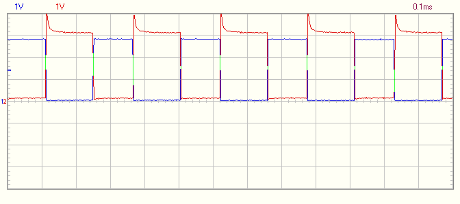
We upload and connect the oscilloscope with one input to the output of the microcontroller (blue line) and the other to the speaker (red).

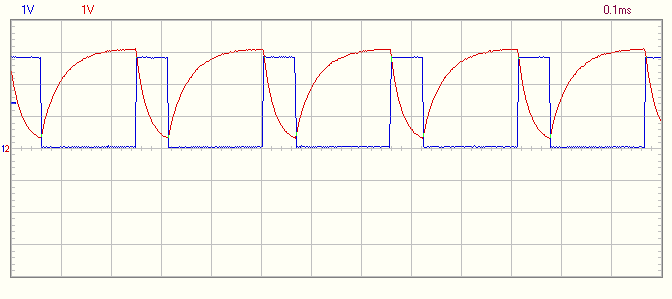
So what do we see? The blue line is the result of the PWM. Fill from 0 to 100% and jump again to zero. But the red line somewhere in the middle of the filling is vaguely similar to a sine wave. Frankly, this remoteness is obtained by attaching a 0.47 uF capacitor parallel to the transistor, for a beautiful gif. The real picture can be seen below.
We remove the capacitor.

See the peaks on red? This “reverse” speaker works like a generator and easily throws a whole volt when powered by 3x. In principle, subject to certain conditions, it is easy to burn the circuit. But here, these peaks do not bother anyone, so whether or not to install a Conder is up to you. I set for the sake of beauty.
We will put it again. It already was, but this picture is static.

Change to 0.1 μf. Just to compare and display the effect of capacitance on sound :)

In principle, we already got a squeak of 15 kilohertz, but who needs it, except for mosquitoes? So you need to twist the frequency. The frequency of the PWM depends on the timer, and how often the timer will “tick” depends on the counter that is set each time the timer starts.
That is, the algorithm of the timer looks something like this
- Start the timer.
- The timer ticked and decreased the counter.
- The counter is at zero? If not, then tick again. If so, generate an interrupt.
Interrupt handler:
- OH! Timer ticked!
- Reset timer again
And now the start of the PWM is just with us hooked to the timer interrupt. And we can twist both the frequency of the "tick input" (prescaler in the settings) and the counter value.
Change the code (it's stage2)
uint8_t count;
for(count=0;count<256;count++)
  {
    PWM4_LoadDutyValue(count*2);
    TMR2_LoadPeriodRegister(count);
     __delay_ms(100);
  }

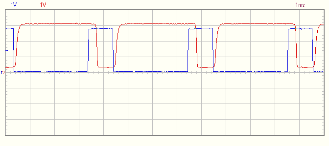
We look at the beautiful red line and see that we get something distant to a sinusoid, and changing in frequency. Yes, and the ear confirms. What we need!
Why am I changing the PWM filling, I propose to think on my own. But in principle, if you mentally continue the graph and slow down the change in one parameter, then everything becomes clear. Particularly advanced ones can see a similar picture in some emulator, for example proteus.
Now we’ll determine what frequency range we got. We
beat count at 255

And now we set at 10

Pay attention to the upper right corner, where the grid step is indicated. “By eye” I got a range of about 300-5000Hz. Quite. And the skull "ride" will not.Perfectionists can use a frequency meter, or calculate the real value from the clock frequency and prescalers.
But then I had problems. I don’t have any understanding of how it should sound. Roughly speaking, in Chukchi music the reader, but not the writer.
I hardly found in half what frequencies corresponded to which notes, I found some kind of musical notation “a Christmas tree was born in the forest” ... I
calculated the delays, wrote
#define do 243 //523Hz
#define re 239 //587
#define mi 236 //659
#define fa 231 //739
#define sol 229 //783
#define la 224 //880
#define si 218 //987
// and again +523Hz
const uint8_t elka[29]={do,la,la,sol,la,fa,do,do,do,la,la,si,sol,do,do,re,re,si,si,si,la,sol,fa,do,la,la,sol,la,fa};
void play(uint8_t p)
{
    // 255 - 3ms period - 300Hz
    // 10 - 0,2ms - 5000Hz
    PWM4_LoadDutyValue(p*2);
    TMR2_LoadPeriodRegister(p);
}
....
uint8_t count;
for (count = 0; count < 29; count++) {
  play(elka[count]);
   __delay_ms(300);
  PWM4_LoadDutyValue(0);
  TMR2_LoadPeriodRegister(0);
   __delay_ms(50);
}
Compiled, launched. No, the melody is guessed without problems, but it's not like that. By selecting resistors and capacitors, I achieved an “almost sinusoid saw” at the output, but the ear hears the difference.
In the end, I stopped at the usual two-tone signal: “high-low”. The classic policeman “wow-wow”, known to everyone from Hollywood films, did not work out for me. And Google in response to the "police sirene tones code programm example" gives anything, just not what you need.
Help, please? In what sequence does the scumbling go there?
In principle, we have already come to the point of taking and reproducing the usual wav as the next step. That is, do not suffer with tones and other things. Just record the sound, translate it into a digestible form and play. As different ScreamTrackers did at the time.
There is only one problem: half a second of sound in PCM format, mono, with 8KHz sampling, takes about a kilobyte. And I have only three and a half kilobytes. It won’t work. But you can familiarize yourself with the principles and examples simply by entering Google “pic pcm sound”. And right from the first link will be the source and the programs themselves.
Therefore, we are comforted by the fact that we will have a real, “warm tube sound from those times”, for which the programmer does not need attention: he said what frequency to stick and went about his own business, and there the pieces of iron will do everything themselves.
But sound is half the battle. Good light is also a hallmark of this tuning :) But this is a bit later.
As usual, a finished project for MPLAB with all the pieces can be picked up here.