STM32 and FreeRTOS. 5. We bring good and good!
- Tutorial
Just in case, otherwise sanctions will be applied (smail). The described case has nothing to do with reality and is entirely an invention of the author.
Earlier it was about streams , semaphores , queues, and HAL.
Once they asked me to look at one very expensive device. There was one problem: among those using this device, there was a strong belief that 99.99% of its price comes from the fact that the manufacturer of this device is a monopolist in its field and there is nowhere for users of this device to go.
Armed with an oscilloscope, I climbed inside.
After some time, the search led to two wires that were in a bundle connecting the units of the device. The waveform showed that the wiring is almost the usual USART. Almost - because “there” the data ran at a speed of 9600, and back to 115200. I
took out two usb-usart adapters, hooked their inputs to RX / TX and began to analyze the protocol. The task was complicated by different speeds, asynchrony and binary protocol. In general, after a while I found that my eyes were widening, trying to track in the terminals what was going on and what it was responding to.
To save you vision and reason in a similar situation, let's make usart hardware sniffer. Moreover, we will do it so that he would not care at the speed and sequence of transfers. Well, after understanding usart, you can then add an analysis of the legs and all sorts of SPI at the same time.
The work of the sniffer will be simple: the STM32 has a bunch of built-in USART. Let 2 of them listen to their RX legs and then send them out via USB. And we will attach these legs to the RX / TX of the device under study.
To get started, we take the already (hopefully) familiar STM32F3DISCOVERY board and use STM32Cube to create a blank. This blank should have the following
5 threads.
defaultTask - will blink the LED “the device is working and not hung”
Usart1Rx - will receive data on the 1st port
Usart2Rx - the same thing, then on 2m
UsbSend - here the data will be processed and sent out to
Usart3Tx - and this will be a test stream that will send quotes from famous robots. We use to check the operability of the first two ports "to the input." Well, or for pampering.
And one turn - in which the packages from the "receivers" of the data will be added. In order not to bother, I made such a structure
To begin with, we will write the most important function - sending test data.
And we’ll check it by simply catching on with an external usart-usb adapter for suitable legs. This will at least give an understanding of what to expect at the “reception” if we simply connect the RX-TX legs directly on the board.
Now let's move on to the function that accepts and formalizes the received.
From the previous articles and knowledge of the C language, it becomes clear that we are just waiting for the next “premise” and, depending on the conditions, set the flags.
Well, then we wait until the USB interface is ready and just form (I admit, it can be more accurate) a line and display it to the user. I didn’t paint it here, because there work with the buffer and lines “on the forehead”, without any optimizations.
Now you need to write what we will receive data from.
Usart2Rx is exactly the same. If anything, then in the real code I left comments for inquisitive users.
Finally, the USART interrupt handler
Pay attention to the comment in the middle and why for the second port it is not commented out
At the request of one of the attentive readers: Also pay attention to what I used in the interrupt handler xQueueSend instead of xQueueSendFromISR . This is done on purpose, so that the controller during the test process "and so it can" (or, in simple words, when the speed on the serial port is raised somewhere to 57600-115200) starts to hang regularly. Just turning on the debugger would indicate that it was waiting while trying to write to a crowded queue. Inside the real code there are a couple more of these “traps”.
We compile, assemble and look at the terminal.
It seems that it is necessary. We hook to the 1st port another “data source” and simply copy the string into it.
By the way, a very good question for the “how interrupts work” trial is - why don't the lines from both ports interrupt each other?
But to confirm that not everything is so bad, I bring another screenshot where I simply tapped the keyboard.
As you can see, if there is a “sho”, then one port can “kill” the other.
And finally, the most interesting feature of the resulting analyzer. If in the initialization code of the physical USART port add the following lines
That microcontroller will itself, on the fly, adjust to the speed of the start bit. It is very useful for cases when at first the devices are “sniffed” for identification at a low speed, and then they switch to a high speed.
That's all. Returning to the seed: an exchange dump between the modules was obtained in a completely analogous way, rather quickly “poked” by parts, and after a while the expensive device was replaced with a stobax box that exceeded it in the key (for the customer) parameter. True, the producer still didn’t stop paying money (there were a bunch of other reasons there), but they got rid of the fear of “it’ll break down and the process needs to be controlled”.
As usual, a complete set of sources can be taken here
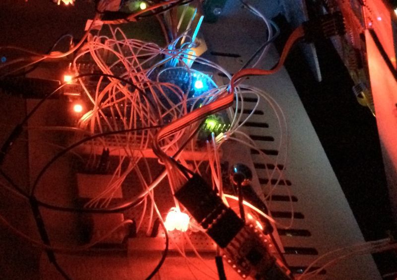
PS In the photo in the header is a model of a laser surgery device for which we wrote firmware at studiovsemoe.com. It has nothing to do with the device itself . Just a beautiful picture turned out.
Earlier it was about streams , semaphores , queues, and HAL.
Once they asked me to look at one very expensive device. There was one problem: among those using this device, there was a strong belief that 99.99% of its price comes from the fact that the manufacturer of this device is a monopolist in its field and there is nowhere for users of this device to go.
Armed with an oscilloscope, I climbed inside.
After some time, the search led to two wires that were in a bundle connecting the units of the device. The waveform showed that the wiring is almost the usual USART. Almost - because “there” the data ran at a speed of 9600, and back to 115200. I
took out two usb-usart adapters, hooked their inputs to RX / TX and began to analyze the protocol. The task was complicated by different speeds, asynchrony and binary protocol. In general, after a while I found that my eyes were widening, trying to track in the terminals what was going on and what it was responding to.
To save you vision and reason in a similar situation, let's make usart hardware sniffer. Moreover, we will do it so that he would not care at the speed and sequence of transfers. Well, after understanding usart, you can then add an analysis of the legs and all sorts of SPI at the same time.
The work of the sniffer will be simple: the STM32 has a bunch of built-in USART. Let 2 of them listen to their RX legs and then send them out via USB. And we will attach these legs to the RX / TX of the device under study.
To get started, we take the already (hopefully) familiar STM32F3DISCOVERY board and use STM32Cube to create a blank. This blank should have the following
5 threads.
defaultTask - will blink the LED “the device is working and not hung”
Usart1Rx - will receive data on the 1st port
Usart2Rx - the same thing, then on 2m
UsbSend - here the data will be processed and sent out to
Usart3Tx - and this will be a test stream that will send quotes from famous robots. We use to check the operability of the first two ports "to the input." Well, or for pampering.
And one turn - in which the packages from the "receivers" of the data will be added. In order not to bother, I made such a structure
typedef struct {
	uint8_t usart;
	uint8_t byte;
} myMes;
To begin with, we will write the most important function - sending test data.
for(;;)
{
        // Wall-e: Eeeee... va?
	uint8_t walle[]="Eeeee... va?\r\n";
	// Short Circuit: Johny Five is Alive!
	uint8_t johny[]="Johny Five is Alive! \r\n";
	// StarWars
	uint8_t c3po[]="Sir, the possibility of successfully navigating an asteroid field is approximately 3,720 to 1 \r\n";
	HAL_UART_Transmit(&huart3,(uint8_t *)&walle,15,16); //PB10
	HAL_UART_Transmit(&huart2,(uint8_t *)&johny,23,100); //PA2
	HAL_UART_Transmit(&huart1,(uint8_t *)&c3po,97,100);  //PC4
        osDelay(1000);
	HAL_GPIO_TogglePin(GPIOE, GPIO_PIN_15);
}
And we’ll check it by simply catching on with an external usart-usb adapter for suitable legs. This will at least give an understanding of what to expect at the “reception” if we simply connect the RX-TX legs directly on the board.
Now let's move on to the function that accepts and formalizes the received.
xQueueReceive( RecQHandle, &w, portMAX_DELAY );
if(oldusart!=w.usart || char_count>16)
	{
	oldusart=w.usart;
	newline=1;
	char_count=0;
	}
buf[char_count++]=w.byte;
From the previous articles and knowledge of the C language, it becomes clear that we are just waiting for the next “premise” and, depending on the conditions, set the flags.
Well, then we wait until the USB interface is ready and just form (I admit, it can be more accurate) a line and display it to the user. I didn’t paint it here, because there work with the buffer and lines “on the forehead”, without any optimizations.
Now you need to write what we will receive data from.
void Usart1Rx(void const * argument)
{
  /* USER CODE BEGIN Usart1Rx */
  /* Infinite loop */
  for(;;)
  {
		if(HAL_UART_Receive_IT(&huart1, &b1,1)==HAL_OK)
		{
			HAL_GPIO_TogglePin(GPIOE, GPIO_PIN_9);
		}
	osDelay(1);
  }
  /* USER CODE END Usart1Rx */
}
Usart2Rx is exactly the same. If anything, then in the real code I left comments for inquisitive users.
Finally, the USART interrupt handler
void HAL_UART_RxCpltCallback(UART_HandleTypeDef *UartHandle)
{
	myMes m;
	HAL_GPIO_TogglePin(GPIOE, GPIO_PIN_14);
	switch((uint32_t)UartHandle->Instance)
	{
		case (uint32_t)USART1:
			HAL_GPIO_TogglePin(GPIOE, GPIO_PIN_10);
		  m.usart=1;
		  m.byte=b1;
		  xQueueSend( RecQHandle, &m, portMAX_DELAY  );
		  // Do this need?
      //HAL_UART_Receive_IT(&huart1, &b1,1);
		  break;
		case (uint32_t)USART2:
			HAL_GPIO_TogglePin(GPIOE, GPIO_PIN_12);
		  m.usart=2;
		  m.byte=b2;
		  xQueueSend( RecQHandle, &m, portMAX_DELAY  );
		  HAL_UART_Receive_IT(&huart2, &b2,1);
			break;
	}
}
Pay attention to the comment in the middle and why for the second port it is not commented out
At the request of one of the attentive readers: Also pay attention to what I used in the interrupt handler xQueueSend instead of xQueueSendFromISR . This is done on purpose, so that the controller during the test process "and so it can" (or, in simple words, when the speed on the serial port is raised somewhere to 57600-115200) starts to hang regularly. Just turning on the debugger would indicate that it was waiting while trying to write to a crowded queue. Inside the real code there are a couple more of these “traps”.
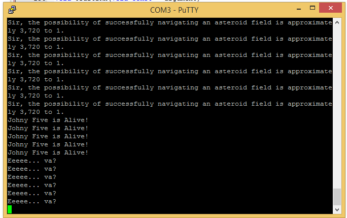
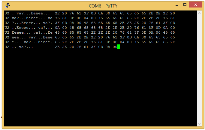
We compile, assemble and look at the terminal.
It seems that it is necessary. We hook to the 1st port another “data source” and simply copy the string into it.
By the way, a very good question for the “how interrupts work” trial is - why don't the lines from both ports interrupt each other?
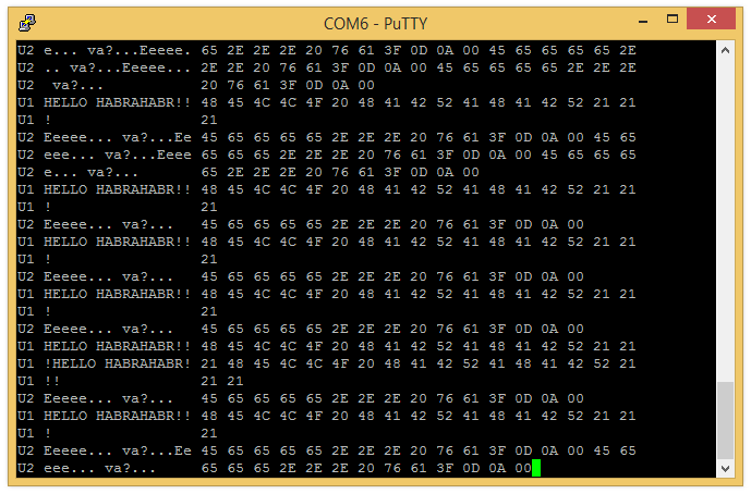
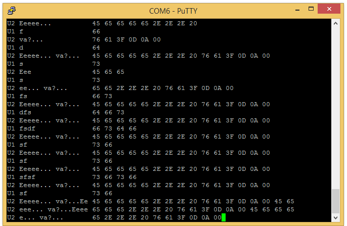
But to confirm that not everything is so bad, I bring another screenshot where I simply tapped the keyboard.
As you can see, if there is a “sho”, then one port can “kill” the other.
And finally, the most interesting feature of the resulting analyzer. If in the initialization code of the physical USART port add the following lines
huart1.Init.OneBitSampling = UART_ONEBIT_SAMPLING_DISABLED ;
huart1.AdvancedInit.AdvFeatureInit = UART_ADVFEATURE_AUTOBAUDRATE_INIT;
huart1.AdvancedInit.AutoBaudRateEnable = UART_ADVFEATURE_AUTOBAUDRATE_ENABLE;
huart1.AdvancedInit.AutoBaudRateMode = UART_ADVFEATURE_AUTOBAUDRATE_ONSTARTBIT;
That microcontroller will itself, on the fly, adjust to the speed of the start bit. It is very useful for cases when at first the devices are “sniffed” for identification at a low speed, and then they switch to a high speed.
That's all. Returning to the seed: an exchange dump between the modules was obtained in a completely analogous way, rather quickly “poked” by parts, and after a while the expensive device was replaced with a stobax box that exceeded it in the key (for the customer) parameter. True, the producer still didn’t stop paying money (there were a bunch of other reasons there), but they got rid of the fear of “it’ll break down and the process needs to be controlled”.
As usual, a complete set of sources can be taken here
PS In the photo in the header is a model of a laser surgery device for which we wrote firmware at studiovsemoe.com. It has nothing to do with the device itself . Just a beautiful picture turned out.