Radio electronics, or how I began to comprehend it
Good afternoon, dear community.
All the time I was surprised by people who understand radio electronics. I have always considered them a kind of shaman: how can one sort out this abundance of elements, tracks and documentation? As soon as you look at the board, “poke” the oscilloscope a couple of times in only one place that he understands and with the words “a, I see,” take the soldering iron in your hands and resurrect it, as if it were your favorite toy. It cannot be called magic otherwise.
The heyday of radio electronics in our country came in the 80s, when there was nothing and everything had to be done with your own hands. Many years have passed since then. Now I get the impression that with the generation of the 70s, knowledge with skill also leaves. I was not lucky: half of the heyday of my parents planned me, and the second half I spent playing cubes and other cars. When I went to the Young Technician club at age 12, these were not the most prosperous times, and due to circumstances, six months later I had to “tie up” with the club, but the dream remained.
For current activities, I am a programmer. I realize that finding the error in the big code is exactly the same as finding the “bad” capacitor on the board. No sooner said than done. Since by nature I like to study on my own, I went to look for literature. There were several attempts to start, but every time I started reading books I rested on the fact that I could not understand basic things, for example, “what is voltage and current strength”. Requests to the great and terrible Google also gave template answers copied from textbooks. I tried to find a place in Moscow where you can learn this skill - the search did not end with the result.
So, welcome to the beginner amateur radio club.
I love to learn and learn something new, but just knowledge is not enough for me. At school, they taught me the skill “a theorem cannot be learned - you can only understand it” and now I carry this rule through my life. People around me look with bewilderment when, instead of taking ready-made solutions and putting them together quickly, I start reinventing my bicycles. The second reason for writing the article is the thought "if you understand the subject, you can easily explain it to another." Well, I’ll try to understand it myself and explain it to others.
My first goal, just like in books, is an analog radio, and there we go and into the digital.
I want to warn you right away - the article was written by an amateur in radio electronics and physics and is rather a discussion. All amendments will be glad to hear in the comments.
So, what is voltage, current, and other resistance? In most cases, an analogy with water is given to understand electrical processes. We will not depart from this rule, though with small deviations.
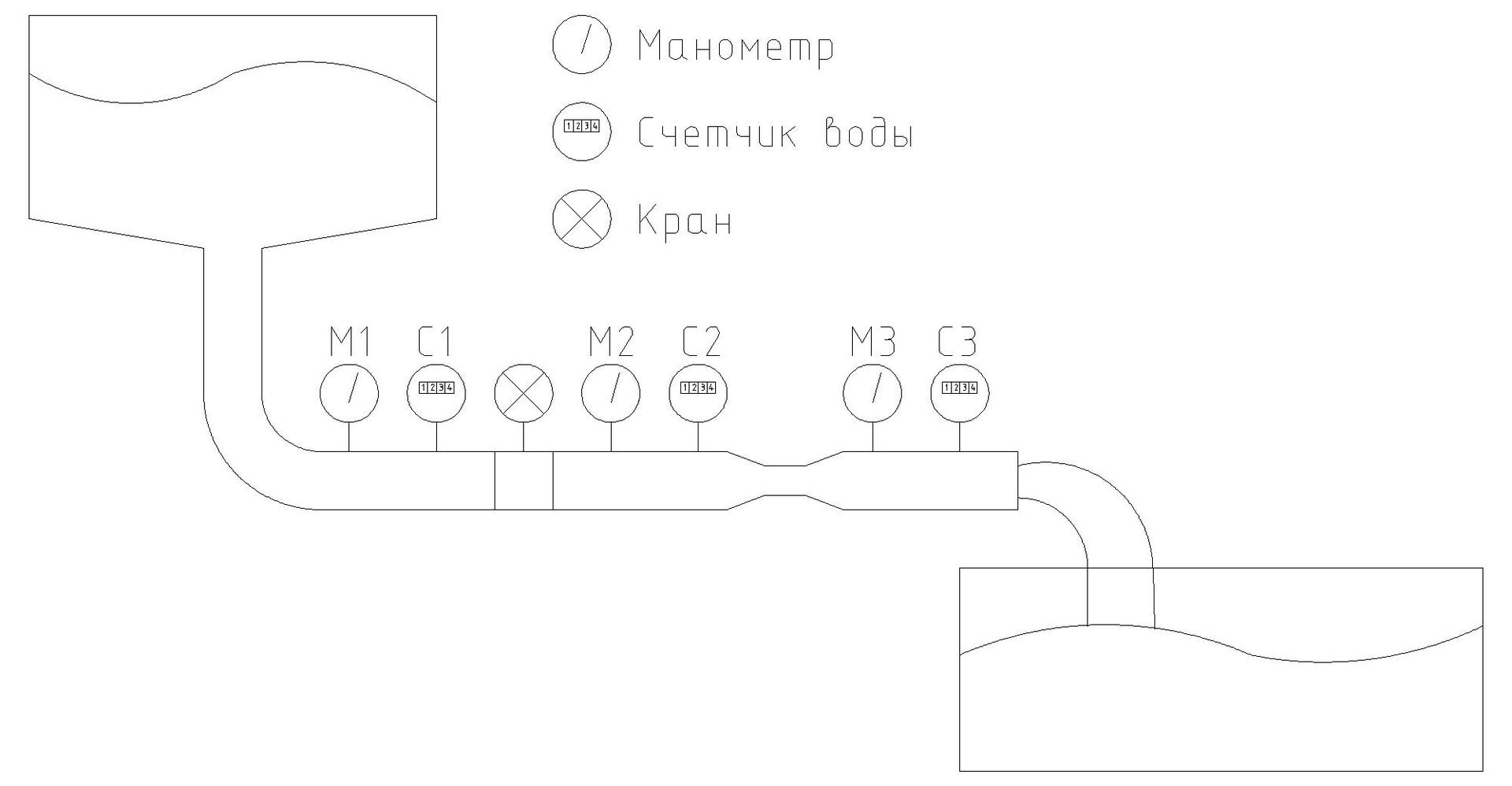
Imagine a pipe. To control some indicators, we will include several water flow meters, pressure gauges for measuring pressure, and elements that interfere with the flow of water.
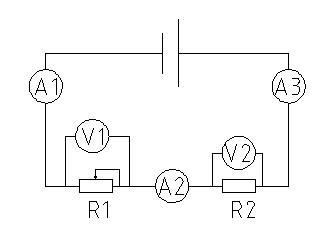
In electrical equivalent, the circuit will look something like this:
The physics course tells us that voltage is the potential difference between two points. If we shift the definition to our pipe with water, then the potential is the pressure, that is, the voltage is the pressure difference between the two points. This explains the principle of its measurement with a voltmeter. It turns out that if we try to measure the stress at two neighboring points of the pipe, where there are no resistance to water movement (there are no taps and restrictions, we will neglect the internal friction of water on the pipe walls) and the pressure does not change - then the pressure difference at these two points will be zero . If resistance is present, there is a decrease in pressure (voltage drop in electrical equivalent), then we will obtain the voltage value. The sum of the voltages at all elements is equal to the voltage at the source. Those. if we add the readings of all voltmeters in our circuit,
For example, we assume that our battery gives a voltage of 5 volts and the resistors have a resistance of 100 and 150 Ohms. Then, according to Ohm's law, U = IR, or I = U / R, we find that a current flows with a force of I = 5/250 = 20mA along the circuit. Since the current strength in the entire circuit is the same (the explanation is a bit further), it follows from Ohm's same law that the first voltmeter will show U = 0.02 * 100 = 2V, and the second U = 0.02 * 150 = 3V.
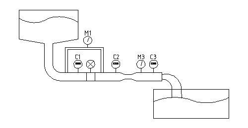
From the same course of physics it is known that this is the amount of charge per unit time. In the water equivalent, this is water itself, and its meter, ammeter - is a water meter. Again, it becomes clear why the ammeter is connected to an open circuit. If you connect it to the place of, for example, the V1 voltmeter, then a new circuit is formed, from which the resistance R1 will be excluded, which means at least we get incorrect values (which will be "as maximum" will become clear a little later). Let's go back to our little water - connecting the ammeter in parallel to any of the elements means that part of the water will go through the main pipe, and the other part will go through the counter - and this counter will lie.
Oh yes, about the chain. In most literature, I came across the phrase that batteries are only a source of voltage, and only resistances are a source of current. How so? How can resistance be a source of something else but a source of resistance (heat does not count so far)? That's right, if you rely on Ohm’s law I = U / R, however, do not apply resistance, the current will not appear until there is a voltage source and a closed circuit (just like if you plug our pipe on the right with a stopper that you don’t do - the water meters will be silent) !
Resistance in the circuit should simply be present, because if it is equal to zero, the current will rush to infinity. We see this situation in the “closure” - sparks this is a very large current strength, and more precisely the heat equal to Q = (I ^ 2) Rt (the formula is valid at constant current strength and resistance).
Another important point - when considering the calculation of voltage and current strength, I did not find clarifications that in a closed circuit in all sections the current strength will be the same. Those. all counters will spin at the same speed and show the same values. In fact, the amount of current that has passed through the circuit is similar to the amount of “water” coming out of the pipe.
Perhaps the simplest phenomenon to explain. Returning to our pipe, resistance is all possible contractions and taps. According to what we have discussed above, with increasing resistance, the current in the entire circuit decreases and the voltage at the ends of the resistance decreases. Or again in water realities - closing our tap half a turn will cause a decrease in water flow at all meters and a proportional (depending on resistance) pressure drop on the pressure gauges.
So where does everything fall and decrease? Here the analogy with water is ambiguous, since in the case of electricity, the "surplus" turns into heat and dissipates. The amount of heat that is released in this case can again be calculated by the formula Q = (ΔI ^ 2) Rt (again with constant resistance). If we divide the amount of heat by time, we get the power that needs to be applied when choosing the resistor P = Q / t = (ΔI ^ 2) R.
Alternating current, as such, is rarely used in electronics. It is at least made permanent and in most cases reduced. Apparently this is what the literature that came to me almost does not mention him.
What is its difference? From the philistine point of view, in the small - the direction of the current in it changes. Here, the analogy with the pipe is not entirely appropriate, the first thing that comes to mind is a shaker for cocktails (the liquid, when mixed in it, walks back and forth). We in radio electronics need to know how the current goes in our circuit in order to get from it what we want.
The next thing I went to deal with is semiconductors. Holes? Electrons? Key mode? Cascades? Field effect transistor, then the one found in the field? Nothing is clear yet ...
All the time I was surprised by people who understand radio electronics. I have always considered them a kind of shaman: how can one sort out this abundance of elements, tracks and documentation? As soon as you look at the board, “poke” the oscilloscope a couple of times in only one place that he understands and with the words “a, I see,” take the soldering iron in your hands and resurrect it, as if it were your favorite toy. It cannot be called magic otherwise.
The heyday of radio electronics in our country came in the 80s, when there was nothing and everything had to be done with your own hands. Many years have passed since then. Now I get the impression that with the generation of the 70s, knowledge with skill also leaves. I was not lucky: half of the heyday of my parents planned me, and the second half I spent playing cubes and other cars. When I went to the Young Technician club at age 12, these were not the most prosperous times, and due to circumstances, six months later I had to “tie up” with the club, but the dream remained.
For current activities, I am a programmer. I realize that finding the error in the big code is exactly the same as finding the “bad” capacitor on the board. No sooner said than done. Since by nature I like to study on my own, I went to look for literature. There were several attempts to start, but every time I started reading books I rested on the fact that I could not understand basic things, for example, “what is voltage and current strength”. Requests to the great and terrible Google also gave template answers copied from textbooks. I tried to find a place in Moscow where you can learn this skill - the search did not end with the result.
So, welcome to the beginner amateur radio club.
I love to learn and learn something new, but just knowledge is not enough for me. At school, they taught me the skill “a theorem cannot be learned - you can only understand it” and now I carry this rule through my life. People around me look with bewilderment when, instead of taking ready-made solutions and putting them together quickly, I start reinventing my bicycles. The second reason for writing the article is the thought "if you understand the subject, you can easily explain it to another." Well, I’ll try to understand it myself and explain it to others.
My first goal, just like in books, is an analog radio, and there we go and into the digital.
I want to warn you right away - the article was written by an amateur in radio electronics and physics and is rather a discussion. All amendments will be glad to hear in the comments.
So, what is voltage, current, and other resistance? In most cases, an analogy with water is given to understand electrical processes. We will not depart from this rule, though with small deviations.
Imagine a pipe. To control some indicators, we will include several water flow meters, pressure gauges for measuring pressure, and elements that interfere with the flow of water.
In electrical equivalent, the circuit will look something like this:
Voltage
The physics course tells us that voltage is the potential difference between two points. If we shift the definition to our pipe with water, then the potential is the pressure, that is, the voltage is the pressure difference between the two points. This explains the principle of its measurement with a voltmeter. It turns out that if we try to measure the stress at two neighboring points of the pipe, where there are no resistance to water movement (there are no taps and restrictions, we will neglect the internal friction of water on the pipe walls) and the pressure does not change - then the pressure difference at these two points will be zero . If resistance is present, there is a decrease in pressure (voltage drop in electrical equivalent), then we will obtain the voltage value. The sum of the voltages at all elements is equal to the voltage at the source. Those. if we add the readings of all voltmeters in our circuit,
For example, we assume that our battery gives a voltage of 5 volts and the resistors have a resistance of 100 and 150 Ohms. Then, according to Ohm's law, U = IR, or I = U / R, we find that a current flows with a force of I = 5/250 = 20mA along the circuit. Since the current strength in the entire circuit is the same (the explanation is a bit further), it follows from Ohm's same law that the first voltmeter will show U = 0.02 * 100 = 2V, and the second U = 0.02 * 150 = 3V.
Amperage
From the same course of physics it is known that this is the amount of charge per unit time. In the water equivalent, this is water itself, and its meter, ammeter - is a water meter. Again, it becomes clear why the ammeter is connected to an open circuit. If you connect it to the place of, for example, the V1 voltmeter, then a new circuit is formed, from which the resistance R1 will be excluded, which means at least we get incorrect values (which will be "as maximum" will become clear a little later). Let's go back to our little water - connecting the ammeter in parallel to any of the elements means that part of the water will go through the main pipe, and the other part will go through the counter - and this counter will lie.
Oh yes, about the chain. In most literature, I came across the phrase that batteries are only a source of voltage, and only resistances are a source of current. How so? How can resistance be a source of something else but a source of resistance (heat does not count so far)? That's right, if you rely on Ohm’s law I = U / R, however, do not apply resistance, the current will not appear until there is a voltage source and a closed circuit (just like if you plug our pipe on the right with a stopper that you don’t do - the water meters will be silent) !
Resistance in the circuit should simply be present, because if it is equal to zero, the current will rush to infinity. We see this situation in the “closure” - sparks this is a very large current strength, and more precisely the heat equal to Q = (I ^ 2) Rt (the formula is valid at constant current strength and resistance).
Another important point - when considering the calculation of voltage and current strength, I did not find clarifications that in a closed circuit in all sections the current strength will be the same. Those. all counters will spin at the same speed and show the same values. In fact, the amount of current that has passed through the circuit is similar to the amount of “water” coming out of the pipe.
Resistance
Perhaps the simplest phenomenon to explain. Returning to our pipe, resistance is all possible contractions and taps. According to what we have discussed above, with increasing resistance, the current in the entire circuit decreases and the voltage at the ends of the resistance decreases. Or again in water realities - closing our tap half a turn will cause a decrease in water flow at all meters and a proportional (depending on resistance) pressure drop on the pressure gauges.
So where does everything fall and decrease? Here the analogy with water is ambiguous, since in the case of electricity, the "surplus" turns into heat and dissipates. The amount of heat that is released in this case can again be calculated by the formula Q = (ΔI ^ 2) Rt (again with constant resistance). If we divide the amount of heat by time, we get the power that needs to be applied when choosing the resistor P = Q / t = (ΔI ^ 2) R.
Smoking is not cool!
When I went to the Young Technician circle, the older comrades conducted "experiments" with lighting from electricity. To do this, they took the power supply, connected low-power resistors to it and increased the voltage. Raised until he glowed to red, like a car cigarette lighter. After that, almost a moment later, the resistor “burned out” and went into the bin.
With DC, everything is clear, but AC?
Alternating current, as such, is rarely used in electronics. It is at least made permanent and in most cases reduced. Apparently this is what the literature that came to me almost does not mention him.
What is its difference? From the philistine point of view, in the small - the direction of the current in it changes. Here, the analogy with the pipe is not entirely appropriate, the first thing that comes to mind is a shaker for cocktails (the liquid, when mixed in it, walks back and forth). We in radio electronics need to know how the current goes in our circuit in order to get from it what we want.
The next thing I went to deal with is semiconductors. Holes? Electrons? Key mode? Cascades? Field effect transistor, then the one found in the field? Nothing is clear yet ...