Auto-placement of elements and auto-routing of printed circuit boards
Hello!
I was prompted to write an article by a program that I stumbled into in search of ways to automate the development of printed circuit boards (and I did not find any references, especially articles about it, on the hub). But first things first.
So, the design is developed, assembled on a breadboard, tested in action. Next is the circuit board. If you believe the forums, then many (including my friends) use Sprint-Layout. But this is handmade, the same pencil and piece of paper, only in electronic form. Why all these processor cores and gigabytes of memory if you still have to work with pens? I admit, it always jarred me.
Now I’ll tell you how I achieved a satisfactory result for me in automatic mode.
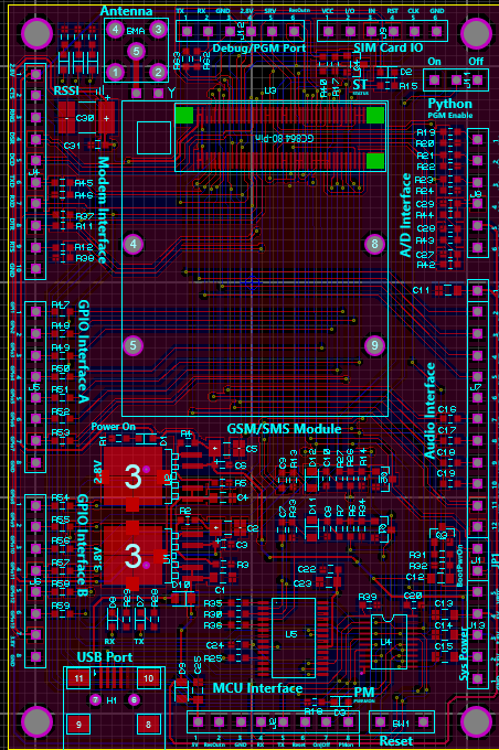
Beautiful picture to attract attention
And I used a bunch of Proteus plus TopoR Lite.
I must say right away that I only relate to these products as a user and in no case do I advertise them. Moreover, Proteus can bespionieri found on the Internet (of course, for educational purposes), and TopoR Lite is free (with some restrictions).
Why exactly these programs?
Originally used by Proteus. I don’t remember how it started, but I was quite happy: you can draw diagrams, simulate work, and lay boards. The first two turned out well, the last did not like, I was looking for an ideal.
I tried to draw a diagram in Eagle. But either I’m a hand-clawed one, or I need special habits and dexterity, in general, I did not like it. At first, I could not figure out how to add an element for a long time. Then it turned out that you need to connect libraries with the necessary elements. And how do I know the name of the library, if I don’t know the name of the element either (for example, I search for connectors exclusively from pictures). In Eagle, by default, I did not have the Attiny2313 and Atmega328 that I needed. I had to google / download / copy the desired library. Well, the power buses in Proteus are connected right away (and even these pins are hidden on the microcircuits, which should be distracting), but here we had to scatter them explicitly. The result after half an hour of poking turned out to be one microcircuit connected to power.
I tried to draw in DipTrace. In principle, drawing is convenient. However, there is no (or did not find) a simulation of the work, I need this both for debugging the circuit, and for debugging MK programs. Got up and returned to ISIS.
Why an external TopoR tracer, if ARES has a built-in? He is sad. He simply throws those chains that he cannot break. If with a two-sided wiring this almost does not happen, with a one-sided and minimal dimensions of the board, horror is obtained. And since I have one-sided textolite, and it’s more difficult to make two-sided boards, I decided - on the one hand I want plus jumpers.
Auto-placement in ARES is also terrible, but I did not find any alternatives, but I don’t want to do anything manually. As they say, on fishlessness and pike cancer.
So, I propose to consider automation tools on a standard example from Proteus 8 - Thermo.
Go to ARES, remove all the beauty that the cunning creators of Proteus have done and click on Auto-placer. This opens up another drawback of this tool: it can only place components on one side of the board (I spent half an hour looking for a solution until I read in the help that this was impossible). Those. if you use both SMD and conventional enclosures and you want them to be on different sides of the board, you will have to use the handles to move the components from one side to the other, each separately.
The result of the auto-placement is the following picture:

In order to see how the autorouter works in ARES, go to the Design Rule Manager, set the POWER and SIGNAL roads on one side only (I have Top Copper), T25 width (so that there are no problems with LUT) and start Auto -router.
Here is the result:
That is, he did not part 43 tracks and will have to make jumpers.
Well, let's try TopoR.
Again, click Auto-router, there Export Design File and save. In TopoR Import -> Specctra and open the file. Now you need to configure a bit. In the Design Parameters (F4) we remove the extra 14 layers, in the Width of the conductors we set from 0.3 to 0.6 mm. We click the Auto Routing button, in the settings of the daw Reassign functionally equivalent component contacts (just in case: it seemed to me that this option does not work at all or even does not work at all), Single-layer tracing and click the Run button. The tracer automatically saves the best options that you can then add to the project. Tracing will end only after clicking the Stop button. I’ll draw your attention to the fact that jumpers are placed automatically, and even contact pads are placed under them. I waited until the number of transitions reached 30 (i.e. 15 jumpers):
15 jumpers versus 43 in ARES - much better!
After spending 5 minutes and slightly moving the components / pushing the boundaries of the board, you can get 10 transitions (5 jumpers), which is already permissible:
But as for me - moving 5 minutes is already much more fun than putting everything from scratch on the board.
White circles are DRC violations (tracks / components are too close). It doesn’t matter - manually manually move these same components and tracks and press F7 - they will neatly reposition, the errors are fixed (however, I saw how this very F7 is buggy: after the next press, it lays one of the roads on top of several others, and then swears about the error) .
The curvature of the tracks, specific to TopoR, blows warm luster and reminds us of the times when boards were spread with a pencil on a piece of paper in a cell, and on a textolite they were painted with nitro-paint / nitro-varnish and a needle / syringe / gel pen paste. Personally, this is rushing me.
When the result is satisfactory, you can either export the board or print directly from the program (there is even a checkmark Mirror Image, apparently especially for LUT).
An example of a real board: You

can draw polygons in TopoR, moreover, they are solid / stroke / grid, but I forgot about them. On this board I drew them with a marker for disks. Shaded spots are just jumpers.
I would be glad if the article helped someone automate boring processes. I would be grateful if you talk about more convenient tools for auto-placement and auto-tracking (especially auto-placement).
I was prompted to write an article by a program that I stumbled into in search of ways to automate the development of printed circuit boards (and I did not find any references, especially articles about it, on the hub). But first things first.
So, the design is developed, assembled on a breadboard, tested in action. Next is the circuit board. If you believe the forums, then many (including my friends) use Sprint-Layout. But this is handmade, the same pencil and piece of paper, only in electronic form. Why all these processor cores and gigabytes of memory if you still have to work with pens? I admit, it always jarred me.
Now I’ll tell you how I achieved a satisfactory result for me in automatic mode.
Beautiful picture to attract attention
And I used a bunch of Proteus plus TopoR Lite.
I must say right away that I only relate to these products as a user and in no case do I advertise them. Moreover, Proteus can be
Why exactly these programs?
Originally used by Proteus. I don’t remember how it started, but I was quite happy: you can draw diagrams, simulate work, and lay boards. The first two turned out well, the last did not like, I was looking for an ideal.
I tried to draw a diagram in Eagle. But either I’m a hand-clawed one, or I need special habits and dexterity, in general, I did not like it. At first, I could not figure out how to add an element for a long time. Then it turned out that you need to connect libraries with the necessary elements. And how do I know the name of the library, if I don’t know the name of the element either (for example, I search for connectors exclusively from pictures). In Eagle, by default, I did not have the Attiny2313 and Atmega328 that I needed. I had to google / download / copy the desired library. Well, the power buses in Proteus are connected right away (and even these pins are hidden on the microcircuits, which should be distracting), but here we had to scatter them explicitly. The result after half an hour of poking turned out to be one microcircuit connected to power.
I tried to draw in DipTrace. In principle, drawing is convenient. However, there is no (or did not find) a simulation of the work, I need this both for debugging the circuit, and for debugging MK programs. Got up and returned to ISIS.
Why an external TopoR tracer, if ARES has a built-in? He is sad. He simply throws those chains that he cannot break. If with a two-sided wiring this almost does not happen, with a one-sided and minimal dimensions of the board, horror is obtained. And since I have one-sided textolite, and it’s more difficult to make two-sided boards, I decided - on the one hand I want plus jumpers.
Auto-placement in ARES is also terrible, but I did not find any alternatives, but I don’t want to do anything manually. As they say, on fishlessness and pike cancer.
So, I propose to consider automation tools on a standard example from Proteus 8 - Thermo.
Scheme:
Go to ARES, remove all the beauty that the cunning creators of Proteus have done and click on Auto-placer. This opens up another drawback of this tool: it can only place components on one side of the board (I spent half an hour looking for a solution until I read in the help that this was impossible). Those. if you use both SMD and conventional enclosures and you want them to be on different sides of the board, you will have to use the handles to move the components from one side to the other, each separately.
The result of the auto-placement is the following picture:
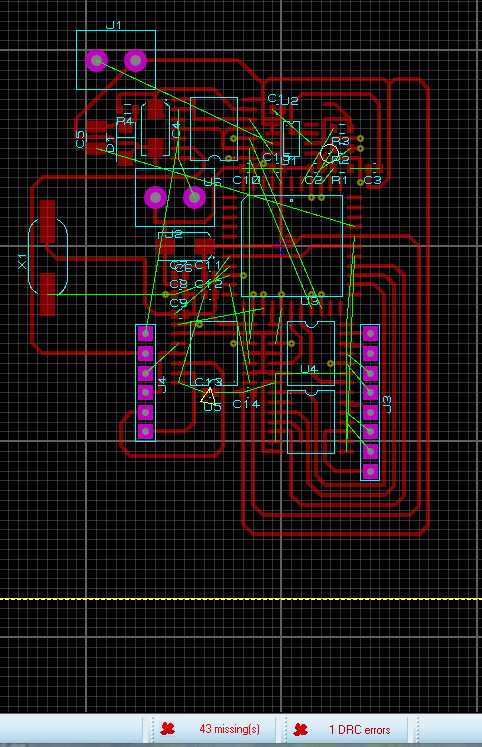
In order to see how the autorouter works in ARES, go to the Design Rule Manager, set the POWER and SIGNAL roads on one side only (I have Top Copper), T25 width (so that there are no problems with LUT) and start Auto -router.
Here is the result:
That is, he did not part 43 tracks and will have to make jumpers.
Well, let's try TopoR.
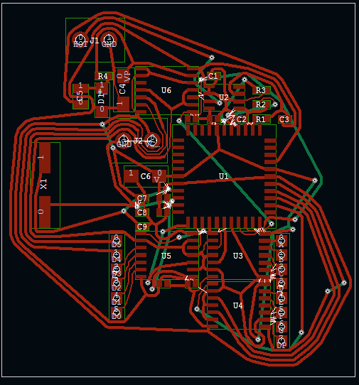
Again, click Auto-router, there Export Design File and save. In TopoR Import -> Specctra and open the file. Now you need to configure a bit. In the Design Parameters (F4) we remove the extra 14 layers, in the Width of the conductors we set from 0.3 to 0.6 mm. We click the Auto Routing button, in the settings of the daw Reassign functionally equivalent component contacts (just in case: it seemed to me that this option does not work at all or even does not work at all), Single-layer tracing and click the Run button. The tracer automatically saves the best options that you can then add to the project. Tracing will end only after clicking the Stop button. I’ll draw your attention to the fact that jumpers are placed automatically, and even contact pads are placed under them. I waited until the number of transitions reached 30 (i.e. 15 jumpers):
15 jumpers versus 43 in ARES - much better!
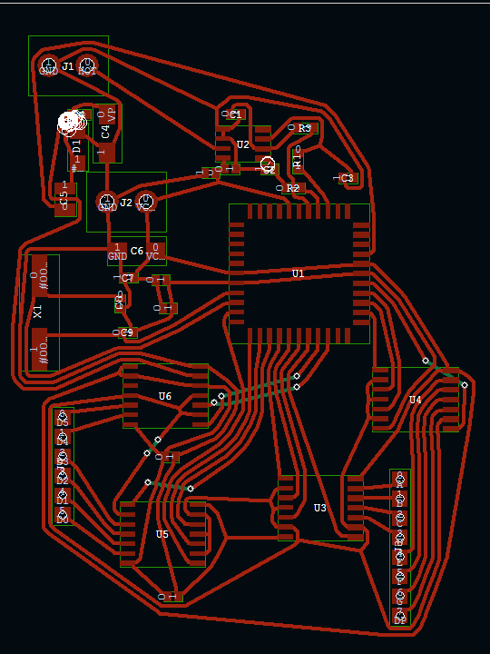
After spending 5 minutes and slightly moving the components / pushing the boundaries of the board, you can get 10 transitions (5 jumpers), which is already permissible:
But as for me - moving 5 minutes is already much more fun than putting everything from scratch on the board.
White circles are DRC violations (tracks / components are too close). It doesn’t matter - manually manually move these same components and tracks and press F7 - they will neatly reposition, the errors are fixed (however, I saw how this very F7 is buggy: after the next press, it lays one of the roads on top of several others, and then swears about the error) .
The curvature of the tracks, specific to TopoR, blows warm luster and reminds us of the times when boards were spread with a pencil on a piece of paper in a cell, and on a textolite they were painted with nitro-paint / nitro-varnish and a needle / syringe / gel pen paste. Personally, this is rushing me.
When the result is satisfactory, you can either export the board or print directly from the program (there is even a checkmark Mirror Image, apparently especially for LUT).
An example of a real board: You
can draw polygons in TopoR, moreover, they are solid / stroke / grid, but I forgot about them. On this board I drew them with a marker for disks. Shaded spots are just jumpers.
I would be glad if the article helped someone automate boring processes. I would be grateful if you talk about more convenient tools for auto-placement and auto-tracking (especially auto-placement).