Restoring the old watch "Electronics-7"
Good day, dear harazhiteli!
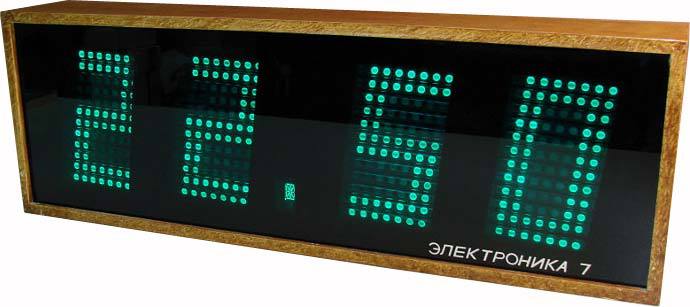
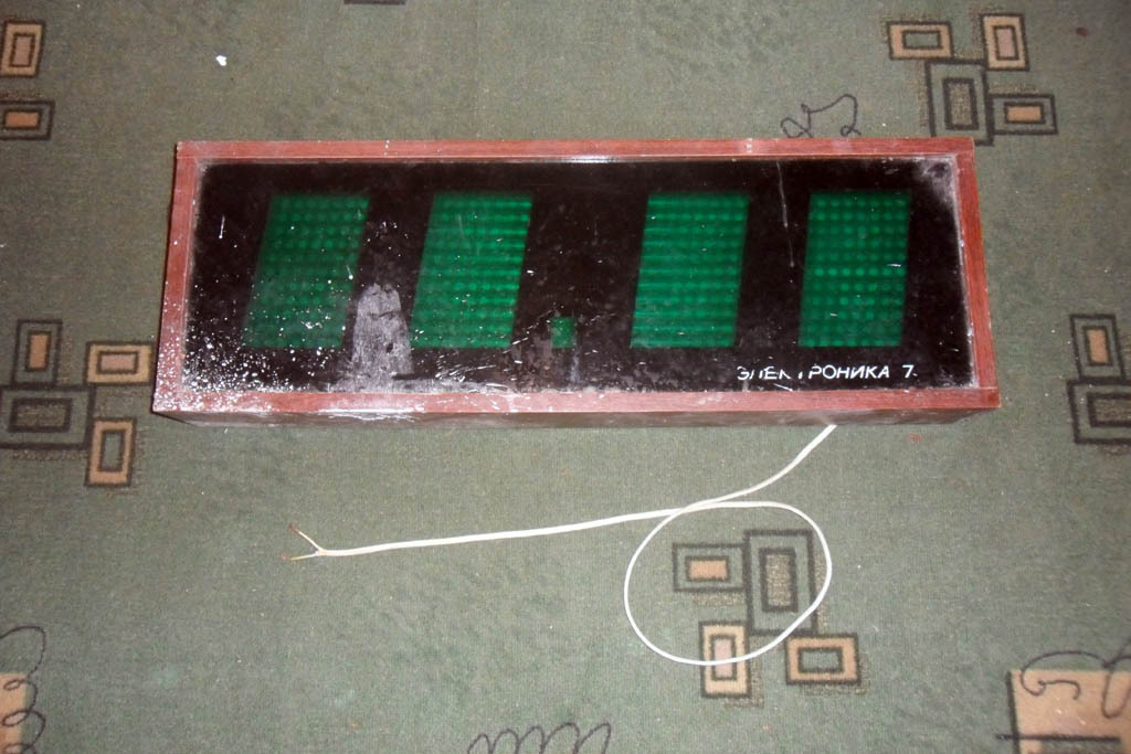
This story began like this. While working at the facility, located in the building of the former plant (it seems, metal structures) with a long name (and, of course, the name of the next great party leader), I saw one thing in the heap of rubbish destined for ejection. What thing hit me with a terrible fit of nostalgia, for exactly the same thing hung in the lobby of the SKB (with no less long and polysyllabic name than the aforementioned factory), where my mother used to work, and where a lot of time has passed from my childhood. Meet the watch “Electronics 7-06”.
Of course, I could not resist the temptation to restore (or maybe modify it?) Them. Who is interested in the process, as well as the final result - I ask for a cut (carefully, a certain number of schemes and photos!).
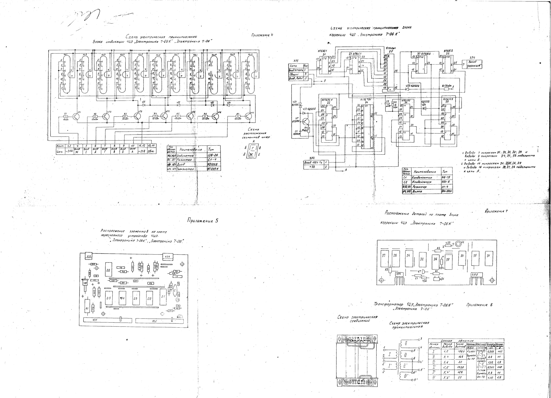
The clock scheme is freely available on the Internet. The elemental base is the 176 series of microcircuits. Indicators - gas-discharge type IV-26. Below is the original diagram. Fig. 1. The original scheme, part 1 Fig. 2. The original scheme, part 2

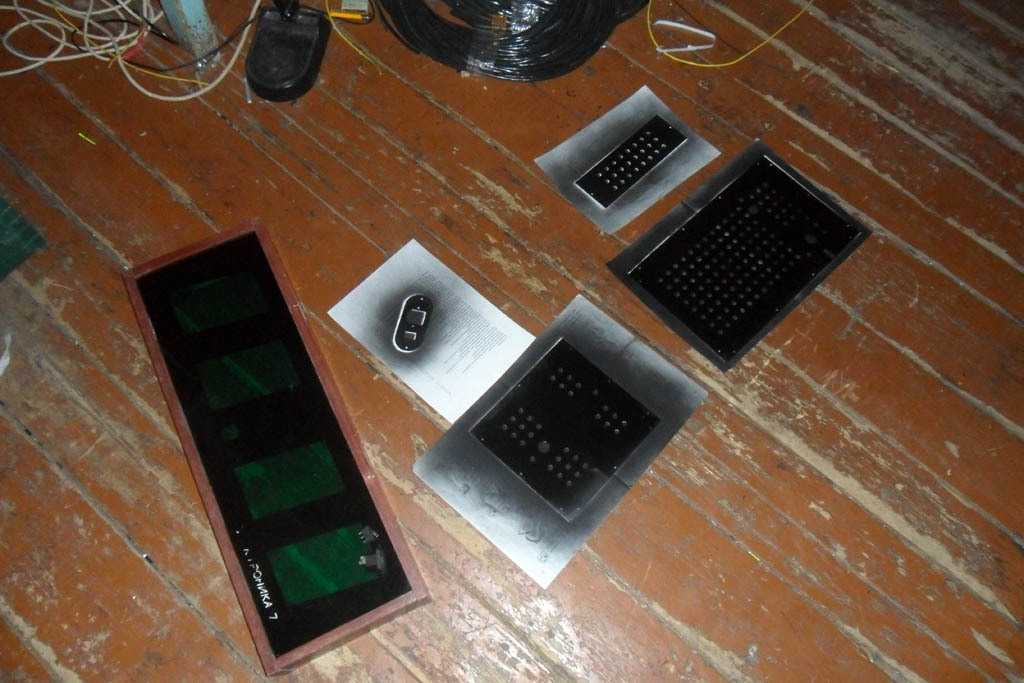
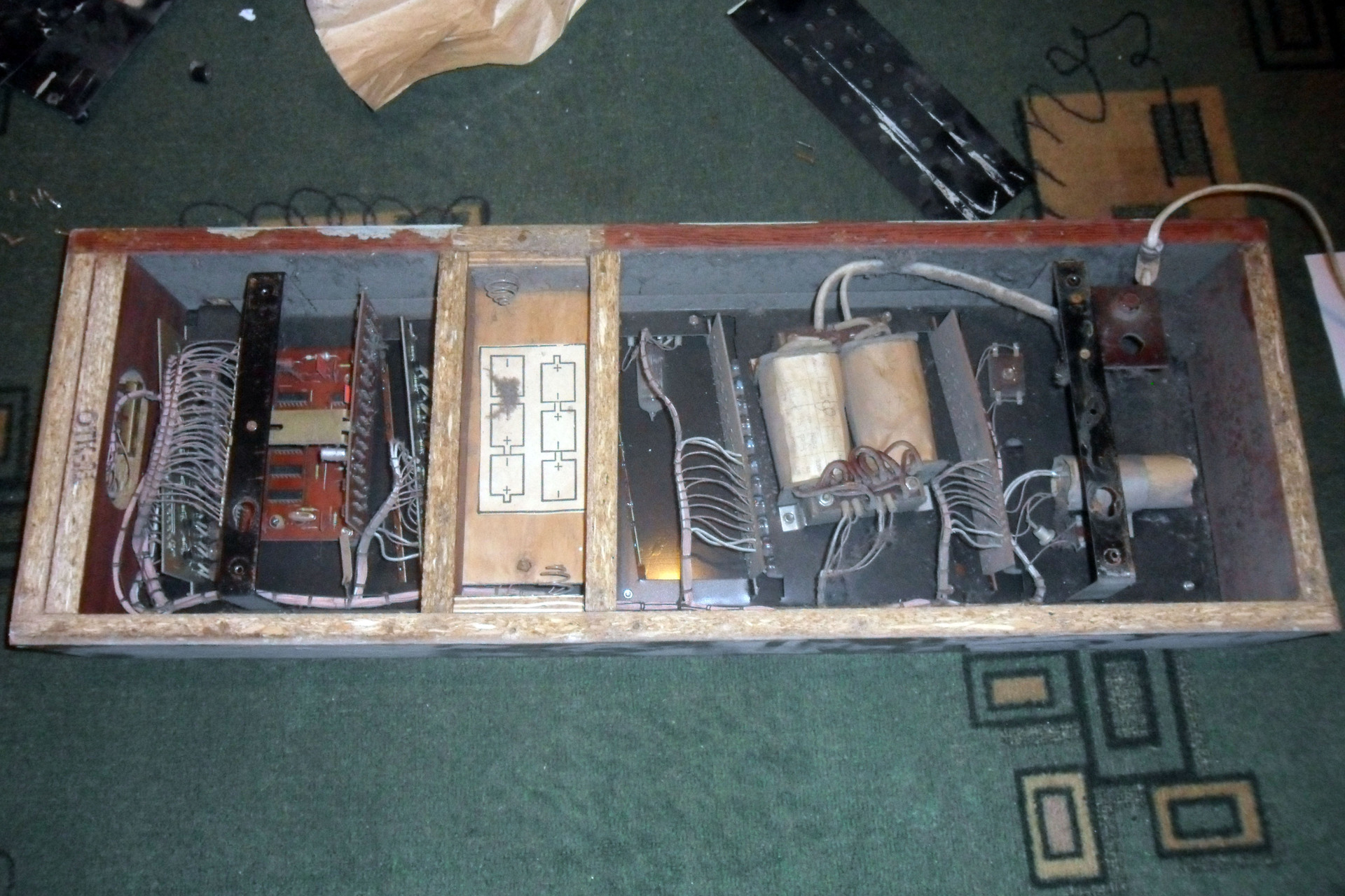
The watch was removed from a pile of garbage, taken home and prepared. After clearing the debris that had accumulated inside, this is what happened to my eyes. Turn on. In principle, everything works. But: indicators burned out. Nowhere to get the same IV-26. Google gives many links telling us how to replace these IV-26s with LEDs, and even with ready-made seven-segment assemblies. But it’s just bad luck - it doesn’t look like that at all ... it’s modern and that’s why it’s poppy, I would say. Therefore, my number one task is to restore the indicators on the LEDs, while preserving the appearance as much as possible.


When I look at the combs from the wires leading to the board, as well as at the diagrams of these boards with adders on the diodes, I feel a little uncomfortable. It is difficult to set up, you can easily mix up the wires. And the outputs of the 176th series are rather weak to directly control LEDs. Plus, I would like to be able to adjust the brightness of the display, preferably according to the scenario, too - at night high brightness is not entirely appropriate at home. The stability of the reference generator on 25-year-old components no one guarantees me either. Having estimated this way and that, I decided to modify the scheme completely.
Each indicator is a 7 x 11 LED matrix, so it comes out by the number of points on the original IV-26. It is controlled by the well-known ATtiny2313. It stores in itself images of symbols for display, a table of a character generator, to put it another way. Even without any optimizations of 11 bytes per character, a hundred characters will fit into it, which means that you can potentially not only write numbers on the scoreboard. And I will have 4 such matrices. And what to display, let them receive it by UART. Well, in fact, what will count the time and send data for the scoreboard on this interface - this is later. I will think about it later (c). But only 3 wires are suitable for each matrix - GND, + 5V and Data. I thought that a unidirectional transmission line for this task is enough.
The indication is dynamic, the node on the registers 74HC595 is used to select rows, and the decoder 74HC238 is used to select the column. The design of the AVR + 74HC595 is well described and is of no interest. Unfortunately, tiny2313's SPI is somehow cut, so loading data into registers is done programmatically. Plus, when trying to use SPI, there were problems with the wiring of the board, so I abandoned this idea. The decoder is connected through a transistor assembly ULN2003 to increase power.
Initially, I planned to use an additional transistor controlled by hardware PWM on the T0 timer to adjust the brightness of the LEDs, but there was a problem: PWM, overlapping the dynamic indication (their frequencies, of course, did not match), generated an unpleasant flickering of the LEDs. Therefore, PWM is software, but it is implemented using a column selection decoder. As you can see, the indicator has 7 columns, and the outputs of the decoder are 8, and the last output is not connected. Choosing it, we extinguish the entire matrix.
The LED current is limited by resistances. Based on the documentation for the applied LED-5213-PGC-6cd, 3 - 3.5V drops at a current of 20 mA, we take an average of 3.2V. Plus another 1V drop on ULN2003. Total (5 - 3.2 - 1) / 0.02 = 40 Ohms. I took on 39 ohms.
Switches SA1 sets the address of the board. This approach allows you to make all 4 boards the same.
Unfortunately, I have not yet mastered the metallization of holes at home. Therefore, the board is single-layer and the number of jumpers on it can be horrifying, although it was minimized by all efforts.
The circuit diagram is shown below. Fig. 3. Schematic diagram of the indicator And here is a photo of the board at one of the stages of manufacture (a photoresist has just been applied and developed). The exchange protocol is very simple: The first byte is always FF, this is the packet header. The second byte is the address of the board. The third byte is the data to display, the character code according to ASCII. Fourth is the desired brightness in the range 00 - FE.

At the end - the lower 8 bits of the sum of all bytes of the packet, integrity check. If the sum is FF, replace it with FE. Package example:
FF 01 32 80 B2 - display the symbol “2” on the board with address 1, brightness - half of the maximum.
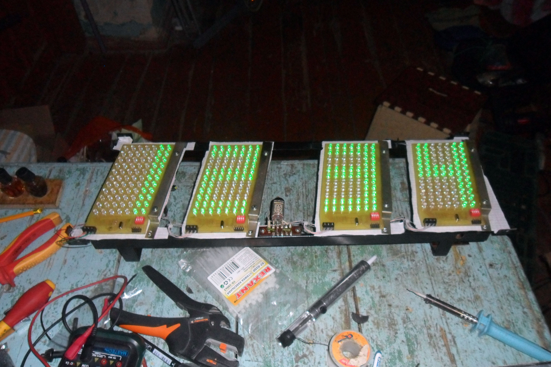
In the process of writing the code, I also got the idea to make the display board display its address at the time of start, before receiving the first data. It turned out to be convenient when debugging.
The native unit contains a transformer with two windings: one produces 22V, which were used to power the anodes of the indicators, and 3.8V to power their glows. Capacitors, of course, lost their capacity, in addition, we need + 5V. So, the scheme will have to be reviewed. In addition, it is possible to power the logic from 6 batteries of 1.5 V each, so that time does not go astray when de-energized. Batteries are somehow not serious, they require regular replacement, so I redid this unit to work with a standard 6V battery, 4.5 Ah.
However, w, 22 * 1.41 = 31V. Well, you can’t do the usual 7805 here, unless we want to screw here the function of a room heater. A short google, and LM2576-5.0 comes to the rescue - an integrated switching regulator with an output current of up to 3A, which was even found in a local radio parts store.
Finding where I cansteal a free charger circuit to reduce the number of bikes created brought me here(in general, the site is dedicated specifically to bicycles, which in the context of the phrase smiles somewhat). However, the circuitry is on linear stabilizers ... however, there is a version of the aforementioned LM2576 with tunable output voltage. In fact, you need to pile the source with a restriction of the form "the output voltage is about 6-14V (with tuning so that the battery can be hooked up to 12V), the output current is not higher than 0.5A (also with tuning)." After some thought, something happened.
Fig. 4. Power supply scheme
Switching the “charge / work from battery” mode is performed by a conventional mechanical relay with a 220V winding connected in parallel with the primary winding of the power transformer. Somewhat naive, but, paradoxically, it works.

So it was the same “later” in which I promised myself to think about what time would actually be considered and manage the indicators. And even better if it also synchronizes it with the world. By NTP, for example. Or DAYTIME. Fortunately, there is Wi-Fi in the house. And most importantly, yes. I almost forgot. In this watch, there still remained one native element of the display, which is so touching that I considered it blasphemous to change it. For I can’t recreate the same, and he’s quite a worker. Flashing second point on the IV-4 indicator! Here she also needs to blink.
For a long time I picked forums for pairing AVR and Wi-Fi, watched how they did it on Arduino ... but the price depresses me. And then my eyes fell on the “raspberry”, which was lying on a shelf, bought for the purpose of studying with the subsequent creation of a torrent download site ...
No, well, it's not even a cannon on sparrows. This is just a hit of the main caliber of the Death Star in order to destroy the evil bacteria under the rim of the toilet bowl. And on the other hand - does it really matter where this torrent rocking chair will stand? There is more than enough space for a USB-HDD in the watch case. In addition, my experience with * nix systems is not very significant yet - a great reason to broaden my horizons. About these thoughts flew through my head, and the fate of raspberries was decided. Well, let it then still show the street temperature, perhaps ... since I’ve got hold of such power. And the sign generator of the board now allows you to draw the pros and cons.
How to fasten a real-time clock to rPi, as well as how to turn it on at all, perform initial configuration, install a torrent client there - it has been said many times before me. However, a number of links that seemed useful to me, I still give below.
I take street temperature from Rambler. The choice is determined by the preferences of my soulmate.
So, step by step all the actions with the "raspberry":
Here we read how to make friends with the TP-Link TL-WN725N Wi-Fi adapter.
And here - how to install a VNC server can come in handy.
Here it is lucidly painted how to raise the Samba.
And here is how to work with the integrated UART.
Here is a script that synchronizes time with the world using NTP.
This script reads weather from Rambler, adding the received data to a file
The main script transmits data via UART to display:
And yes. We blink a second point.
Now add all this economy to cron:
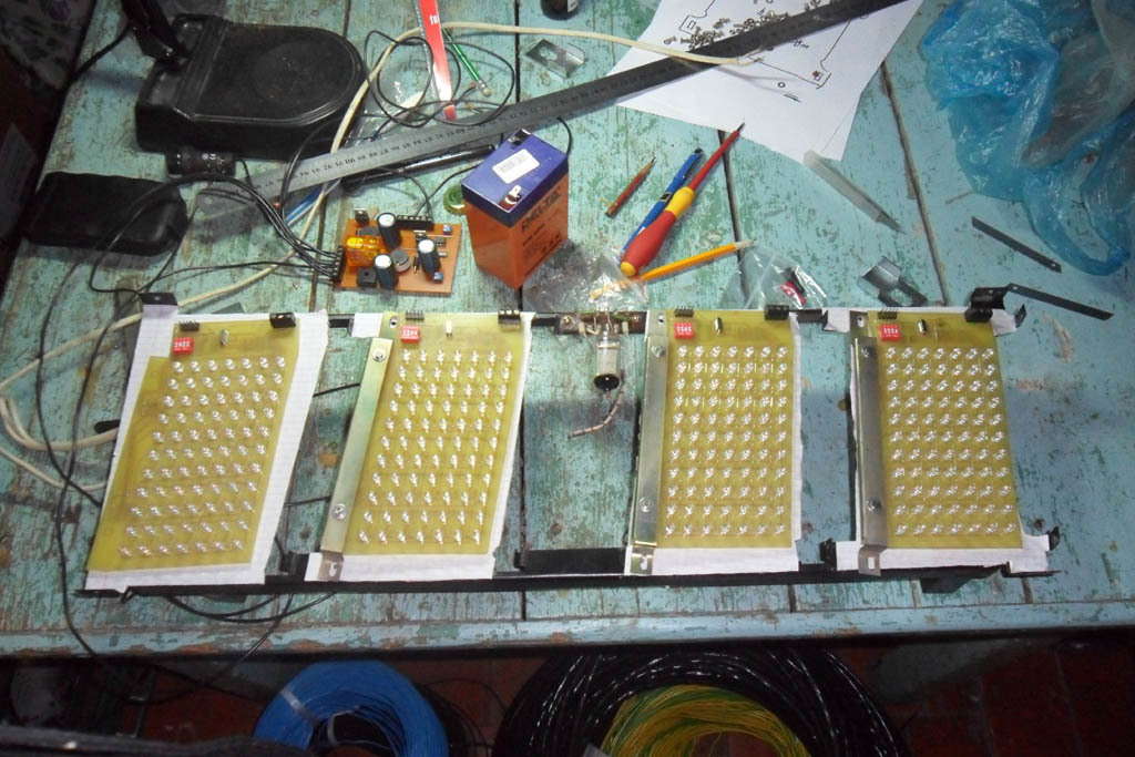
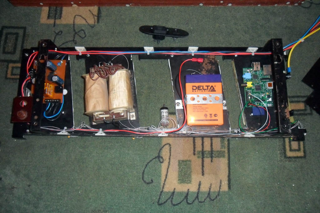
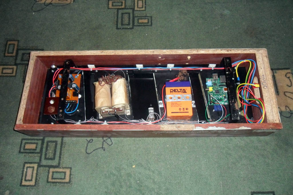
And ... and that’s it. We hang on the wall, enjoy, nostalgic. A photo of the process (clickable), as well as a traditional greeting to the residents of Habr, can be seen below.
Attention! At birth, the author of the article was cut out an artistic feeling that the future engineer did not need. For connoisseurs of unfilled horizons, composition, and any other white balance, please stop reading at this point and proceed immediately to comments, in order to avoid serious mental trauma. Attaching display boards to the chassis. Nearby lies the power supply board. Paint the rusted back covers. The first inclusion in assembled form. The boards display their addresses. All elements are mounted on the chassis. Larger, the same stage. We pack in the case.


Time. Temperature overboard. All circuits, printed circuit boards and firmware can be found here .

This story began like this. While working at the facility, located in the building of the former plant (it seems, metal structures) with a long name (and, of course, the name of the next great party leader), I saw one thing in the heap of rubbish destined for ejection. What thing hit me with a terrible fit of nostalgia, for exactly the same thing hung in the lobby of the SKB (with no less long and polysyllabic name than the aforementioned factory), where my mother used to work, and where a lot of time has passed from my childhood. Meet the watch “Electronics 7-06”.
Of course, I could not resist the temptation to restore (or maybe modify it?) Them. Who is interested in the process, as well as the final result - I ask for a cut (carefully, a certain number of schemes and photos!).
1. A bit of theory
The clock scheme is freely available on the Internet. The elemental base is the 176 series of microcircuits. Indicators - gas-discharge type IV-26. Below is the original diagram. Fig. 1. The original scheme, part 1 Fig. 2. The original scheme, part 2


2. Let's start with
The watch was removed from a pile of garbage, taken home and prepared. After clearing the debris that had accumulated inside, this is what happened to my eyes. Turn on. In principle, everything works. But: indicators burned out. Nowhere to get the same IV-26. Google gives many links telling us how to replace these IV-26s with LEDs, and even with ready-made seven-segment assemblies. But it’s just bad luck - it doesn’t look like that at all ... it’s modern and that’s why it’s poppy, I would say. Therefore, my number one task is to restore the indicators on the LEDs, while preserving the appearance as much as possible.


3. Scoreboard
When I look at the combs from the wires leading to the board, as well as at the diagrams of these boards with adders on the diodes, I feel a little uncomfortable. It is difficult to set up, you can easily mix up the wires. And the outputs of the 176th series are rather weak to directly control LEDs. Plus, I would like to be able to adjust the brightness of the display, preferably according to the scenario, too - at night high brightness is not entirely appropriate at home. The stability of the reference generator on 25-year-old components no one guarantees me either. Having estimated this way and that, I decided to modify the scheme completely.
Each indicator is a 7 x 11 LED matrix, so it comes out by the number of points on the original IV-26. It is controlled by the well-known ATtiny2313. It stores in itself images of symbols for display, a table of a character generator, to put it another way. Even without any optimizations of 11 bytes per character, a hundred characters will fit into it, which means that you can potentially not only write numbers on the scoreboard. And I will have 4 such matrices. And what to display, let them receive it by UART. Well, in fact, what will count the time and send data for the scoreboard on this interface - this is later. I will think about it later (c). But only 3 wires are suitable for each matrix - GND, + 5V and Data. I thought that a unidirectional transmission line for this task is enough.
The indication is dynamic, the node on the registers 74HC595 is used to select rows, and the decoder 74HC238 is used to select the column. The design of the AVR + 74HC595 is well described and is of no interest. Unfortunately, tiny2313's SPI is somehow cut, so loading data into registers is done programmatically. Plus, when trying to use SPI, there were problems with the wiring of the board, so I abandoned this idea. The decoder is connected through a transistor assembly ULN2003 to increase power.
Initially, I planned to use an additional transistor controlled by hardware PWM on the T0 timer to adjust the brightness of the LEDs, but there was a problem: PWM, overlapping the dynamic indication (their frequencies, of course, did not match), generated an unpleasant flickering of the LEDs. Therefore, PWM is software, but it is implemented using a column selection decoder. As you can see, the indicator has 7 columns, and the outputs of the decoder are 8, and the last output is not connected. Choosing it, we extinguish the entire matrix.
The LED current is limited by resistances. Based on the documentation for the applied LED-5213-PGC-6cd, 3 - 3.5V drops at a current of 20 mA, we take an average of 3.2V. Plus another 1V drop on ULN2003. Total (5 - 3.2 - 1) / 0.02 = 40 Ohms. I took on 39 ohms.
Switches SA1 sets the address of the board. This approach allows you to make all 4 boards the same.
Unfortunately, I have not yet mastered the metallization of holes at home. Therefore, the board is single-layer and the number of jumpers on it can be horrifying, although it was minimized by all efforts.
The circuit diagram is shown below. Fig. 3. Schematic diagram of the indicator And here is a photo of the board at one of the stages of manufacture (a photoresist has just been applied and developed). The exchange protocol is very simple: The first byte is always FF, this is the packet header. The second byte is the address of the board. The third byte is the data to display, the character code according to ASCII. Fourth is the desired brightness in the range 00 - FE.


At the end - the lower 8 bits of the sum of all bytes of the packet, integrity check. If the sum is FF, replace it with FE. Package example:
FF 01 32 80 B2 - display the symbol “2” on the board with address 1, brightness - half of the maximum.
In the process of writing the code, I also got the idea to make the display board display its address at the time of start, before receiving the first data. It turned out to be convenient when debugging.
4. Power supply
The native unit contains a transformer with two windings: one produces 22V, which were used to power the anodes of the indicators, and 3.8V to power their glows. Capacitors, of course, lost their capacity, in addition, we need + 5V. So, the scheme will have to be reviewed. In addition, it is possible to power the logic from 6 batteries of 1.5 V each, so that time does not go astray when de-energized. Batteries are somehow not serious, they require regular replacement, so I redid this unit to work with a standard 6V battery, 4.5 Ah.
However, w, 22 * 1.41 = 31V. Well, you can’t do the usual 7805 here, unless we want to screw here the function of a room heater. A short google, and LM2576-5.0 comes to the rescue - an integrated switching regulator with an output current of up to 3A, which was even found in a local radio parts store.
Finding where I can

5. The heart of the system
So it was the same “later” in which I promised myself to think about what time would actually be considered and manage the indicators. And even better if it also synchronizes it with the world. By NTP, for example. Or DAYTIME. Fortunately, there is Wi-Fi in the house. And most importantly, yes. I almost forgot. In this watch, there still remained one native element of the display, which is so touching that I considered it blasphemous to change it. For I can’t recreate the same, and he’s quite a worker. Flashing second point on the IV-4 indicator! Here she also needs to blink.
For a long time I picked forums for pairing AVR and Wi-Fi, watched how they did it on Arduino ... but the price depresses me. And then my eyes fell on the “raspberry”, which was lying on a shelf, bought for the purpose of studying with the subsequent creation of a torrent download site ...
No, well, it's not even a cannon on sparrows. This is just a hit of the main caliber of the Death Star in order to destroy the evil bacteria under the rim of the toilet bowl. And on the other hand - does it really matter where this torrent rocking chair will stand? There is more than enough space for a USB-HDD in the watch case. In addition, my experience with * nix systems is not very significant yet - a great reason to broaden my horizons. About these thoughts flew through my head, and the fate of raspberries was decided. Well, let it then still show the street temperature, perhaps ... since I’ve got hold of such power. And the sign generator of the board now allows you to draw the pros and cons.
How to fasten a real-time clock to rPi, as well as how to turn it on at all, perform initial configuration, install a torrent client there - it has been said many times before me. However, a number of links that seemed useful to me, I still give below.
I take street temperature from Rambler. The choice is determined by the preferences of my soulmate.
So, step by step all the actions with the "raspberry":
Here we read how to make friends with the TP-Link TL-WN725N Wi-Fi adapter.
And here - how to install a VNC server can come in handy.
Here it is lucidly painted how to raise the Samba.
And here is how to work with the integrated UART.
Here is a script that synchronizes time with the world using NTP.
timesync.sh
#!/bin/bash
sudo service ntp stop
sleep 5
sudo ntpdate time.nist.gov time.windows.com
sleep 5
sudo service ntp start
This script reads weather from Rambler, adding the received data to a file
getweather.sh
##!/bin/bash
URL="http://api.rambler.ru/weather/informer?content_type=xml"
FILENAME=/home/pi/clock/weather.dat
WEATHER=$(curl ${URL} | grep -o -E "()[\+\-]?[0-9]{1,2}(<\/temp>)" | grep -o -E "[\+\-]?[0-9]{1,2}")
if [ -z ${WEATHER} ]
then
	echo "Get weather failed!"
else
	echo -ne " " > ${FILENAME}
	echo -ne $(printf "%+03d" ${WEATHER}) >> ${FILENAME}
fi
The main script transmits data via UART to display:
send.sh
#!/bin/bash
DATAPATH=/home/pi/clock/weather.dat
declare -i LOW_BRIGHT=5
declare -i HIGH_BRIGHT=100
send_data ()
{
DATA=$1
LEN=${#DATA}
stty -F /dev/ttyAMA0 cs8 -cstopb raw speed 19200 > /dev/null
for((i=0; i<$LEN; i++));
do
ADDRESS=$(printf "%d" $(($i+1)))
CHAR=$(printf "%d" ${DATA:$i:1})
if [ "$CHAR" = "0" ]
then
CHAR=32
fi
HOUR=$(date | cut -c 12-13)
if (("$HOUR" > "20")) || (("$HOUR" < "7"))
then
BRIGHTNESS=$(printf "%d" $LOW_BRIGHT)
else
BRIGHTNESS=$(printf "%d" $HIGH_BRIGHT)
fi
CHECKSUM=$((($ADDRESS+$CHAR+$BRIGHTNESS-1)%256))
if [ "$CHECKSUM" = "255" ]
then
CHECKSUM=254
fi
ADDRESS=$(printf "%o" $ADDRESS)
CHAR=$(printf "%o" $CHAR)
BRIGHTNESS=$(printf "%o" $BRIGHTNESS)
CHECKSUM=$(printf "%o" $CHECKSUM)
MESSAGE="\0377\0$ADDRESS\0$CHAR\0$BRIGHTNESS\0$CHECKSUM"
echo -ne "$MESSAGE$MESSAGE" > /dev/ttyAMA0
done
}
if [ "$1" = "time" ]
then
HOUR=$(date | cut -c 12-13)
MINUTE=$(date | cut -c 15-16)
TIME="${HOUR}${MINUTE}"
send_data $TIME
exit 0
fi
if [ "$1" = "weather" ]
then
WEATHER=$(cat ${DATAPATH})
if [ -z ${WEATHER} ]
then
echo "No weather info found"
exit 0
fi
send_data "$WEATHER"
exit 0
fi
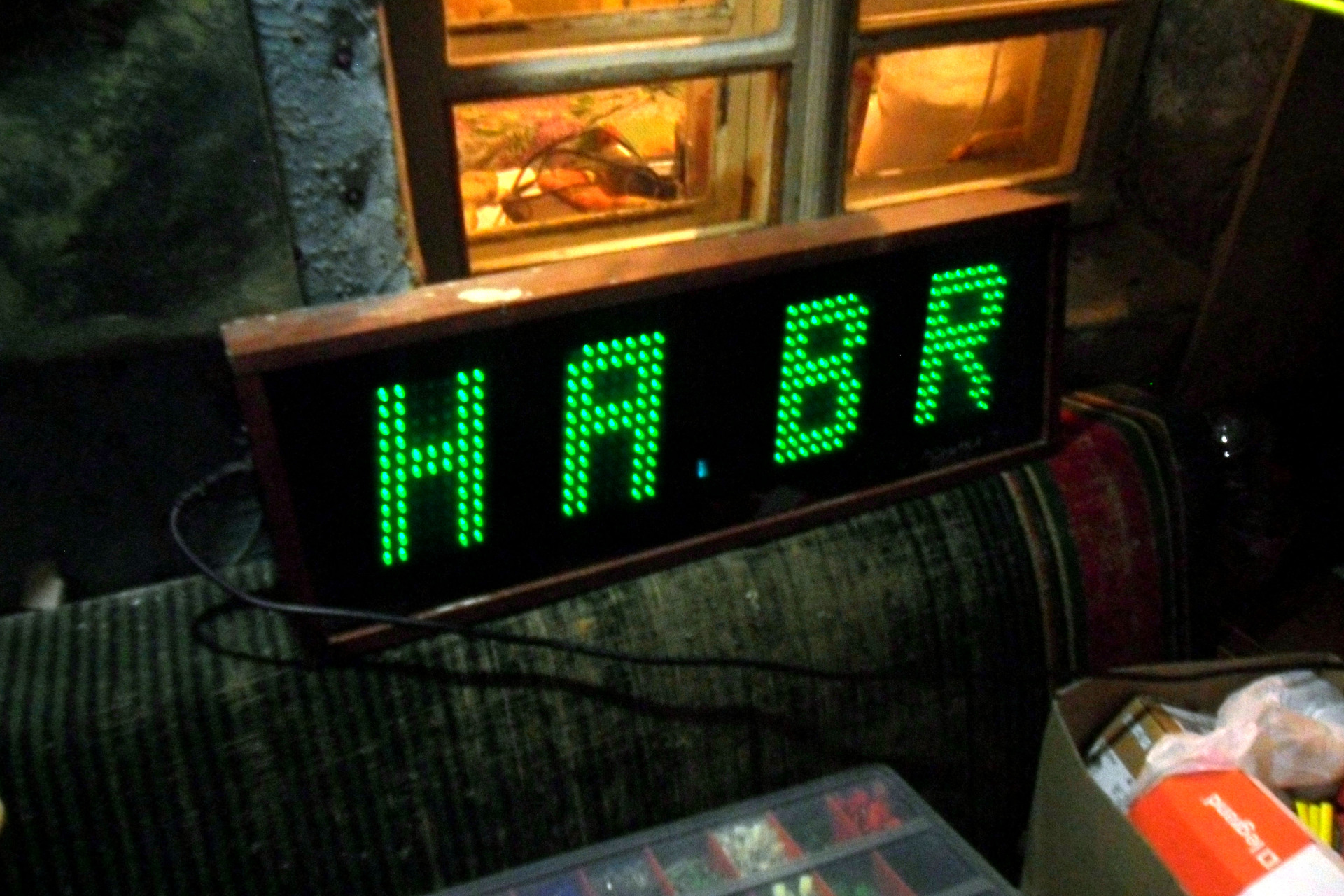
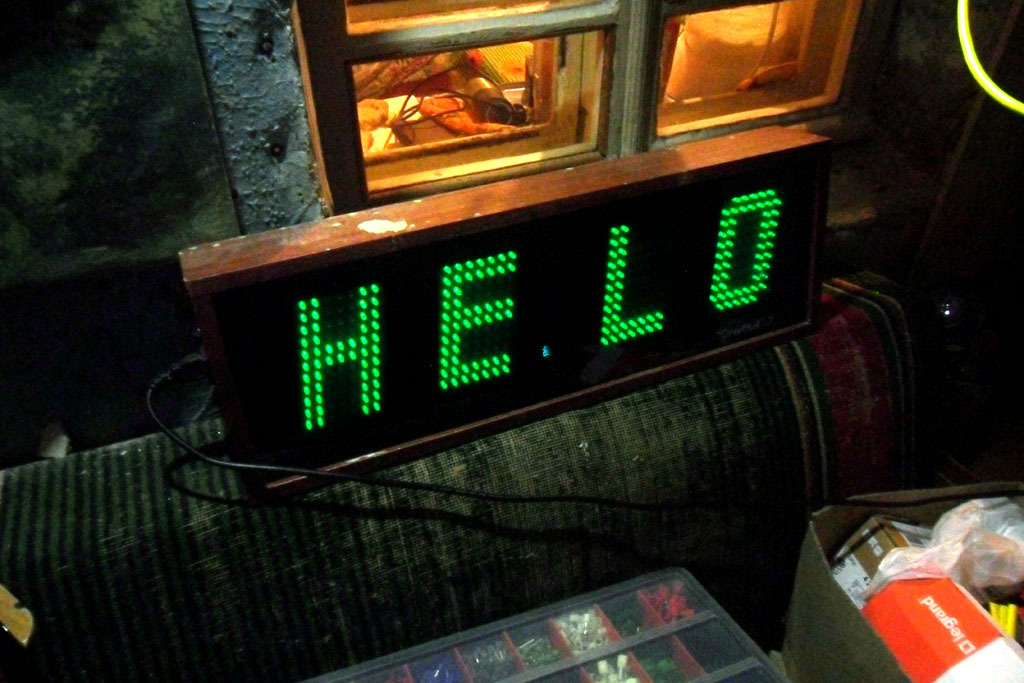
if [ "$1" = "startup" ]
then
send_data "HELO"
sleep 5
send_data "HABR"
sleep 5
send_data " "
exit 0
fi
echo "Usage: send.sh time | weather | startup"
exit 0
And yes. We blink a second point.
blink.sh
#!/bin/bash
sudo echo "25" > /sys/class/gpio/export
sudo echo "out" > /sys/class/gpio/gpio25/direction
while true
do
	echo "1" > /sys/class/gpio/gpio25/value
	sleep 0.5
	echo "0" > /sys/class/gpio/gpio25/value
	sleep 0.5
done
Now add all this economy to cron:
# m h  dom mon dow   command
0/15 * * * * /home/pi/clock/timesync.sh
0/15 * * * * /home/pi/clock/getweather.sh
* * * * * sleep 00; /home/pi/clock/send.sh time
* * * * * sleep 10; /home/pi/clock/send.sh weather
* * * * * sleep 15; /home/pi/clock/send.sh time
* * * * * sleep 25; /home/pi/clock/send.sh weather
* * * * * sleep 30; /home/pi/clock/send.sh time
* * * * * sleep 40; /home/pi/clock/send.sh weather
* * * * * sleep 45; /home/pi/clock/send.sh time
* * * * * sleep 55; /home/pi/clock/send.sh weather
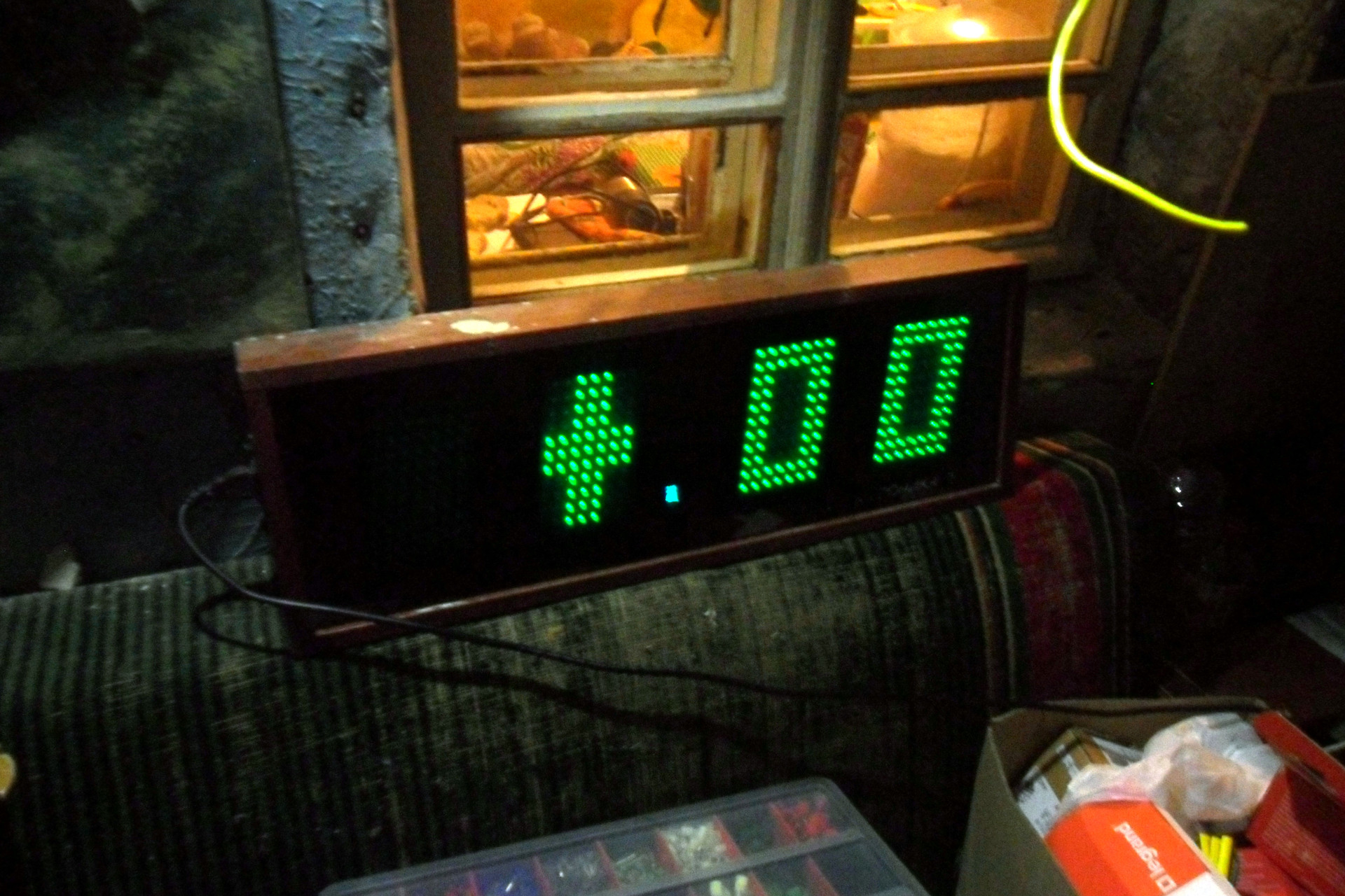
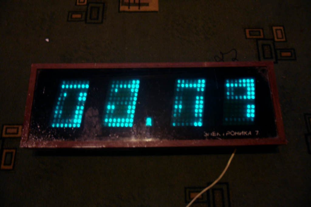
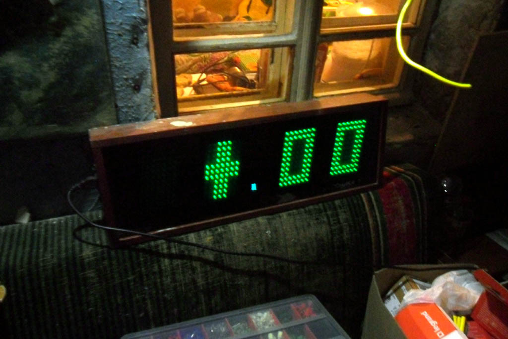
And ... and that’s it. We hang on the wall, enjoy, nostalgic. A photo of the process (clickable), as well as a traditional greeting to the residents of Habr, can be seen below.
Attention! At birth, the author of the article was cut out an artistic feeling that the future engineer did not need. For connoisseurs of unfilled horizons, composition, and any other white balance, please stop reading at this point and proceed immediately to comments, in order to avoid serious mental trauma. Attaching display boards to the chassis. Nearby lies the power supply board. Paint the rusted back covers. The first inclusion in assembled form. The boards display their addresses. All elements are mounted on the chassis. Larger, the same stage. We pack in the case.


And - a logical conclusion!
Time. Temperature overboard. All circuits, printed circuit boards and firmware can be found here .