How to print an electric motor
- Transfer
Axial magnetic flux motor uses printed circuit boards as electromagnetic coils
Translation of an article from the website spectrum.ieee.org, by Carl Bugeja
It all started with the fact that I wanted to make a very small drone. But I quickly realized that one factor limits attempts to reduce and facilitate the project: motors. Even small motors are separate objects that need to be connected to the rest of the electronics and structural elements. So I started thinking about how to merge these elements to save mass.
I was inspired by the fact that some radio systems use antennas, which are copper tracks on a printed circuit board. Is it possible to use something similar to create a sufficiently strong magnetic field capable of feeding the motor? I decided to see if I can create an axial magnetic flux motor using electromagnetic coils, made in the form of tracks on a printed circuit board. In the axial magnetic flux motor, the electromagnetic coils forming the stator are mounted parallel to the rotor made in the form of a disk. Permanent magnets are embedded in the rotor disk. Applying alternating current to the stator coils causes the rotor to rotate.
The first difficulty was to ensure a sufficiently strong magnetic field capable of turning the rotor. It is quite simple to create a flat spiral track and skip current through it, but I limited the motor with a diameter of 16 mm, so the overall diameter of the motor was comparable to the smallest ready-made motors. 16 mm meant that the spiral can make only 10 turns, and there can be only 6 coils located on the disk under the rotor. Ten turns is not enough to get a sufficient magnetic field. However, printed circuit boards are good because today it is quite simple to make a multilayer board. Having printed a pack of coils of four layers, I managed to achieve 40 turns per coil, which is enough to rotate the rotor.
The development process revealed a more serious problem. In order to maintain the rotation of the motor, it is necessary to synchronize a dynamically changing magnetic field between the rotor and the stator. In a typical motor, this is done using alternating current, and the synchronization is obtained naturally, thanks to the arrangement of the brushes electrically connecting the stator and the rotor. In a brushless motor , control electronics with feedback system is required.

In each layer of the circuit there is a set of coils, and they are laid one on another, connecting with each other and forming continuous tracks.
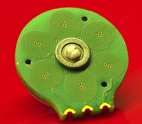
The final four-layer printed circuit board. The

pulses of these coils rotate the rotor printed on a 3D printer, in which the permanent magnets are embedded.
The system is not as powerful as a traditional brushless motor, but printed circuit boards are cheaper and lighter.
In the previous model of the motor I created, I used the back emf as feedback to control the speed. Counter-emf is obtained due to the fact that the rotating motor works as a generator, creating a voltage in the stator coils, counteracting the voltage that turns the motor. Information about counter-emf gives feedback indicating the rotation of the motor, and allows the control electronics to synchronize the coils. But in my motor with printed circuit boards, the back emulsion was too weak to be used. Therefore, I mounted the Hall sensor on it, directly measuring the change in the magnetic field to measure how fast the rotor and its permanent magnets spin over the sensor. This information goes to the motor control electronics.
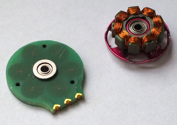
For the manufacture of the rotor, I turned to 3D printing. Initially, I made a rotor, which was mounted on a separate metal rod, but then I just started typing and the rod as an integral part of the rotor. This reduced the number of physical components to a rotor, four permanent magnets, a bearing and a printed circuit board, providing both coil and structural strength.
Soon my first motor was already running. Tests have shown that it consistently provides a static torque of 0.9 g * cm. This was not enough for the implementation of my initial plan for creating an integrated motor for the drone, but I thought that such a motor could still be used as an engine for small and cheap robots moving on the ground on wheels, so I continued my research (usually the motors are most expensive parts of robots). A printed motor can operate with a voltage from 3.5 to 7 V, although at high voltage it heats up significantly. At 5 V its working temperature is 70 ° C, which is quite acceptable. It consumes about 250 mA.
At the moment I am concentrating on increasingtorque I managed to almost double it by adding a ferrite sheet to the back of the stator coils to limit the magnetic field lines. I also plan other prototypes of motors with different winding systems. In addition, I am working on using the same technologies to create a linear actuator that can move a printed slider over a series of 12 reels. I also test a prototype flexible circuit board using the same coils. My goal is to start making new robots using smaller and cheaper mechanisms compared to those available today.