vPath or how to create a service chain in a virtualization environment
 How to provide traffic control between components of a virtualized application with minimal time costs? Is there a technology that allows you to transfer traffic in a chain through several service components, for example, a firewall, a packet filter and a traffic balancing system, without making any changes to the network configuration or the configuration of the applications themselves? Under the cut, we’ll talk about Cisco vPath technology, which allows you to elegantly create service chains in virtualization environments and not depend on the manufacturer of the hypervisor.
1. The statement of the problem
Initial data:
- there is an application that consists of several components, for example, WEB, APP, DB;
- components are virtual machines (VMs) and are located within a cluster of hypervisors;
- all components are connected to the same network segment and use one default gateway to communicate with the outside world.
The network connection organization diagram of the application component looks like in Fig. 1.
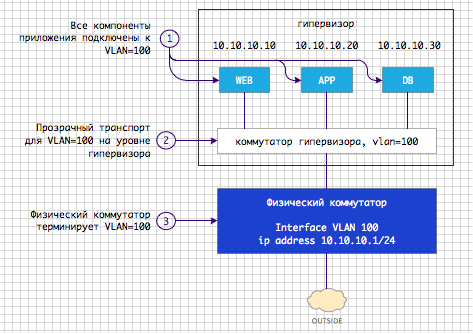
Fig. 1 Logical diagram of the organization of connecting the application to the network
By default, the matrix of interaction between application components and the outside world looks like this.
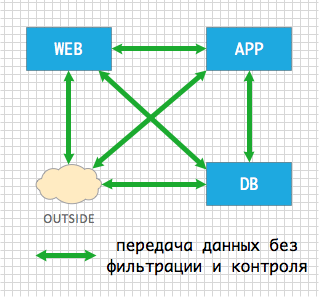
Fig. 2 The initial matrix of interaction between application components The
traffic that is transmitted between application components is not controlled in any way - everything is allowed to everyone.
Statement of the problem in general form:
- without changing the application configuration, provide the ability to control traffic between application components;
- control implies the ability to transparently embed service elements along the path of traffic transfer between application components;
- a service element can be a virtual machine that performs packet filtering, load balancing, deep inspection at the application level, traffic compression, network traffic analysis, etc. etc.;
- the key part of the task - there can be several service elements , and the complexity of embedding should not depend on their quantity;
- It should be possible to build service elements in chains.
An example of a real task # 1 - embedding a packet filter The
ability to control traffic between applications provides a service element called a packet filter, such as Cisco VSG . A packet filter is embedded in the path of data transfer between virtual machines. After embedding the filter, the interaction matrix changes and looks as follows.

Fig. 3 Transparent embedding of the packet filter
Note to Fig. 3 : the figure shows the logical operations that a packet filter performs. In general, one virtual machine can handle this task. This note is also relevant for the diagrams below.
What does a packet filter do:
- Allows incoming traffic from users from the outside segment only to the WEB component of the application;
- traffic from the outside segment to the application components APP and DB is prohibited;
- traffic between pairs of WEB-APP and APP-DB components is allowed over known protocols and ports;
- all other traffic is prohibited.
An example of a real task No. 2 is the creation of service chains
Based on the experience of real projects, often application owners, network and security administrators want more than just packet filtering from their infrastructure. The statement of the problem close to the one that we encounter every day in projects looks something like this.
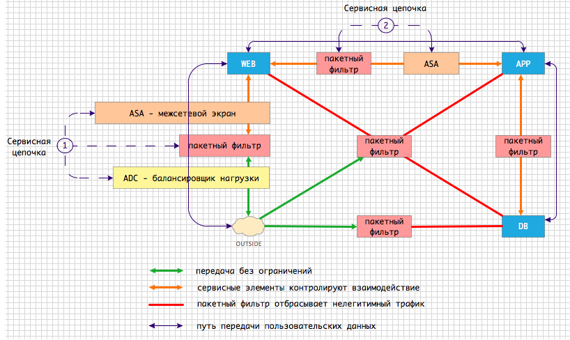
Fig. 4 Service chains between application components
User traffic destined for the WEB component of the application passes through the first service chain:
- traffic must first go to a load balancer, such as the Cisco Netscaler 1000V ;
- then go through rough cleaning on the bag filter;
- Then get on the firewall for more fine- tuning , for example, Cisco ASAv *;
- and only then, balanced, cleaned and inspected traffic should be transferred to the WEB component.
* The current version of ASAv 9.2 (1) does not have vPath support. Its implementation is planned in the near future.
Other service chains with a different set and order of service components may occur along the traffic path. In our example, the second service chain consists of a packet filter and a firewall.
2. The solution of the problem by traditional methods
When creating a service chain using traditional methods, the problem of redirecting traffic from one service component to another is solved by changing the network topology. Let's see how it is possible to solve the just considered “Real Problem No. 2”. Between the service virtual machines and the application, the only possible data transfer path is created, see Fig. 5.
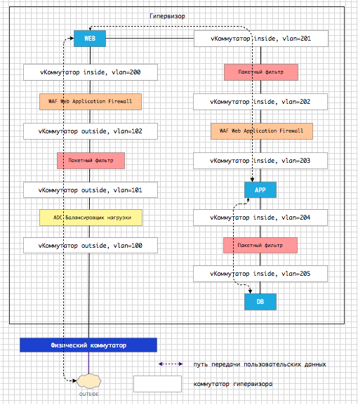
Fig. 5 Creating a service chain by changing topology
Service components are embedded in the physical traffic path. Any logical change in the service chain leads to a physical change in the network topology. As can be seen from Fig. 5. instead of one switch and one VLAN in the original problem, we have 2 logical switches (inside / outside) and 9 VLANs. You can independently calculate how many times the complexity of the topology increases when using the traditional topological method compared to what vPath offers. In place of VLANs, there may be VXLAN topological complexity, this does not decrease.
3. The main question of the article
What can Cisco offer to facilitate the process of creating service chains for applications that are virtualized? How, without increasing the complexity of the infrastructure, how to get a flexible tool that does not depend on the hypervisor?
4. The main answer of the article
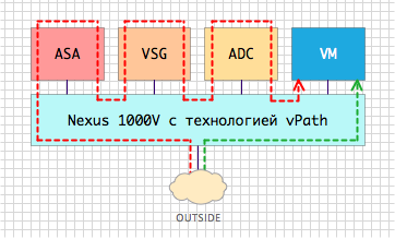
Cisco offers vPath technology that delivers elegant service chaining in a virtualized environment. vPath is a feature of the Cisco Nexus 1000V Distributed Virtual Switch. The Cisco Nexus1000V switch is available today for all major hypervisors - Hyper-V , KVM *, vSphere . Let's take a look at how vPath is designed, how it is configured, and what encapsulation looks like.
* The first release of Nexus 1000V for KVM version 5.2 (1) SK1 (2.2) does not have vPath support. Its implementation is planned for subsequent releases.
5. vPath Architecture
In order to use vPath technology you need:
- Cisco Nexus 1000V Virtual Switch
- service virtual machine that supports vPath.
Let's turn to the initial logical scheme of organizing the network connection of the application, which was presented in Fig. 1. Figure 6 shows the changes that need to be made when implementing vPath.
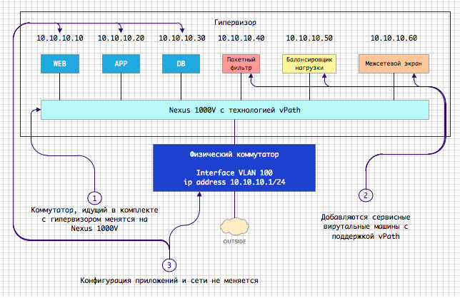
Fig. 6 Key Architectural Components of vPath
What has changed?
- the standard switch that is “attached” to the hypervisor has been replaced with the Nexus 1000V switch;
- WEB, APP, DB virtual machines migrated from a standard switch to the Nexus 1000V;
- service virtual machines with vPath support were also added, which perform the already familiar roles of filtering, balancing and firewalling.
You can add as many service machines as you need to perform traffic operations, or you can do with one packet filter, as we already saw in the Example of real task No. 1. In real scenarios, service functions will probably be combined to reduce costs and topological complexity. No additional switches and new VLAN / VXLANs have appeared. Topologically, the scheme has not changed.
Nexus 1000V Architecture
Before moving on and understanding how vPath works, let's get to know the Nexus 1000V switch device.

Fig. 7 Architecture of the Nexus 1000V switch Nexus 1000V
, as can be seen from Fig. 7, has two components:
- VEM module (Virtual Ethernet Module) - program code that is embedded in the hypervisor and provides traffic switching;
- VSM module (Virtual Service Module) - a component that provides centralized management and configuration of VEM modules.
The Nexus 1000V in its architecture is very similar to a physical modular switch, where VSM - acts as a supervisor (control module), and VEM - acts as a line card.
All settings of the interface used to connect the virtual machine to the VEM module are stored in a design called the Port Profile.
To demonstrate the capabilities of vPath, we will use the Nexus 1000V, which is deployed in our local laboratory. The virtual machine ports in our lab are configured as follows.
port-profile type vethernet V-CONT.WEB
  switchport mode access
  switchport access vlan 21
  no shutdown
  state enabled
port-profile type vethernet V-CONT.APP
  switchport mode access
  switchport access vlan 21
  no shutdown
  state enabled
port-profile type vethernet V-CONT.DB
  switchport mode access
  switchport access vlan 21
  no shutdown
  state enabled
So far, the configuration of all ports is identical. But since we want to implement our own service chain for each of the ports, we set up three different profiles.
The main idea of vPath
The main idea is to create a mechanism that allows you to abstract from the existing network topology and pass traffic through the necessary service components transparently for network devices and end virtual machines. Remember that in all of our source examples, virtual machines are located in the same VLAN?
How does vPath do this?
The VEM module keeps track of all the data streams that are transmitted through it. This data is collected in the Flow Table. The stream is identified by 6 entities: source IP address, destination IP address, source port, destination port, protocol, VLAN. Each time a new stream appears on the network, a new entry appears in the stream table.
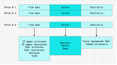
Fig. 8 Table of streams transmitted through the VEM module
The first packet of each newly detected stream is sent to the service device. Thus, the VEM module “asks” the service device the question: can I pass it on or not? When a packet is forwarded to a service device, an additional header with vPath encapsulation is added to it.
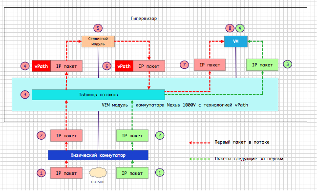
Fig. 9 vPath Logic
The service device inspects the package according to the rules and policies that were configured on it by the security, application, or network administrator. Then the service returns the source package to the VEM module in the same way with vPath encapsulation, which contains the answer - yes, you can transfer the packet further, or - no, you need to discard this package because it does not satisfy the security policy.
VEM module received a package from a service device:
- writes the response to the Action field of the stream table;
- sends the packet to the destination port without vPath encapsulation if the Forward command was in the Action field;
- Moves the package down the chain using the vPath header if the Redirect command was in the Action field.
- discards the packet if the Drop command was in the Action field.
If the nature of the service does not require constant data transfer through the service element, such as in the case of the Cisco VSG packet filter, then all subsequent packets are transmitted bypassing the service element using the response of the service device recorded in the cache.
The following is a simplified vPath algorithm for the case when you need to organize batch filtering between application components.
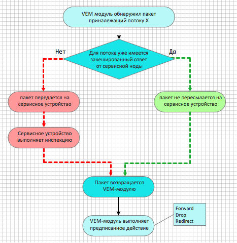
Fig. 10 vPath Algorithm for Cisco VSG
6. Configuring vPath
Now let's move on to the practical setup of the vPath mechanism at our laboratory bench. We have implemented the following topology.

Fig. 11 Laboratory bench topology
First, we register service nodes to which we will redirect traffic.
vservice node ASA-1 type asa
  ip address 10.0.21.1
  adjacency l2 vlan 21
  fail-mode close
vservice node VSG-1 type vsg
  ip address 10.0.21.254
  adjacency l2 vlan 21
  fail-mode close
We check that the Nexus 1000V “sees” the registered modules and their status is Alive.
N1K# show vservice brief
--------------------------------------------------------------------------------
                                   License Information
--------------------------------------------------------------------------------
Type      In-Use-Lic-Count  UnLicensed-Mod
asa                      2
--------------------------------------------------------------------------------
                                   Node Information
--------------------------------------------------------------------------------
 ID Name                     Type   IP-Address      Mode   State   Module
  1 VSG-1                    vsg    10.0.21.254     v-21   Alive   4,
  2 ASA-1                    asa    10.0.21.1       v-21   Alive   4,
<часть вывода опущена>
We create a service chain of 2 previously registered modules.
vservice path WEB-CHAIN
  node VSG-1 profile WEB_SP order 1
  node ASA-1 profile TEST-EDGE-SP order 3
We verify that the Nexus 1000V “sees” the service chain.
N1K# show vservice brief
<часть вывода опущена>
--------------------------------------------------------------------------------
                                   Path Information
--------------------------------------------------------------------------------
Name:WEB-CHAIN                      NumOfSvc:2  Mod:4,
Node                        Order   Profile
 VSG-1                          1   WEB_SP
 ASA-1                          3   TEST-EDGE-SP
--------------------------------------------------------------------------------
<часть вывода опущена>
We connect the service chain, which consists of ASA and VSG, to the profile that defines the connection of the WEB virtual machine to the network.
port-profile type vethernet V-CONT.WEB
  org root/tenant-01
  vservice path WEB-CHAIN
We check that the Nexus 1000V "sees" the configured chain.
N1K# show vservice brief
<часть вывода опущена>
--------------------------------------------------------------------------------
                                   Port Information
--------------------------------------------------------------------------------
PortProfile:V-CONT.WEB
Org:root/tenant-01
Path:WEB-CHAIN
Node                                          Profile(Id)
 VSG-1(10.0.21.254)                           WEB_SP(9)
 ASA-1(10.0.21.1)                             TEST-EDGE-SP(8)
Veth Mod VM-Name                              vNIC IP-Address
  15   4 r1-web-v2                               1 10.0.21.10
<часть вывода опущена>
Now we will make sure that the traffic that is transmitted towards the APP and DB virtual machines is transmitted through the packet filter.
port-profile type vethernet V-CONT.APP
  org root/tenant-01
  vservice node VSG-1 profile APP_SP
port-profile type vethernet V-CONT.DB
  org root/tenant-01
  vservice node VSG-1 profile DB_SP
As a result, with the help of several configuration lines in the laboratory, the following traffic transfer scheme was implemented inside VLAN = 21. At the same time, we did not create new auxiliary switches or VLANs. In Fig. 12 depicts the service chain that has turned out.

Fig. 12 Service chain configured in the example
As can be seen from the presented configuration, it is extremely simple in comparison with the changes that would have to be made if the network topology had to be changed to fit service elements into it. We emphasize once again - the original topology has not changed.
7. vPath encapsulation
vPath packages the source packages in its header as follows.
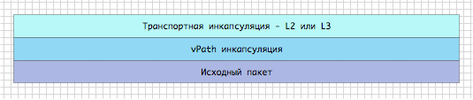
Fig. 13 vPath encapsulation
If the service virtual machine is located in the same segment, the L2 transport header is added to the source packet. If the service machine is in a different segment, then the transport L3 header is added. The body of the original frame does not change. Between the transport header and the source package, there is a vPath header.
vPath header consists of 3 required components:
- base header
- service header
- platform header.

Fig. 14 vPath Header
Base Header:
- contains the protocol version and service chain identifier.
It should be noted that the service chain itself is not included in the header. Only its unique identifier is present there. Information about the chain is stored in a special table Service Table, which, like FlowTable, is on every VEM module. This table is programmed centrally from the VSM module when the system owner makes changes to the configuration.
Service Header:
- implements the approval procedure for the used version of vPath;
- transfers information about profile identifiers on service devices;
- implements the Request / Response procedure between the VEM module and the service device.
Platform Header:
- transfers information specific to the platform that implements vPath;
- Contains the source port identifier
- contains the identifier of the segment type - VLAN, VXLAN;
- contains segment identifier - VLAN number, VXLAN number.
Here is the package that the VEM module received from the virtual machine and redirects to the service module. The latter must decide whether or not this packet can be transmitted further along the service chain. In the service header, we see that the REDIRECT function is being executed. The service module is connected to the VEM module via L2.

Fig. 15 The packet that VEM transmits to the service module
The following screenshot is the packet that the VEM module received from the service module after inspection of the packet. The Service Context Header field contains the RESPONSE identifier, and the ACTION field is set to PERMIT, which means that this packet can be passed on.
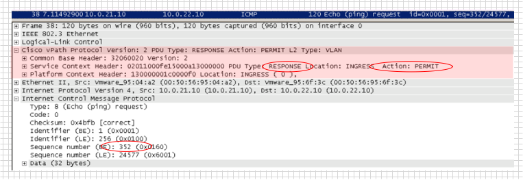
Fig. 16 Package that VEM receives from the service module after inspection
8. Conclusions
In the article, we discussed the problem of creating service chains in the data center. A large number of owners of virtualized infrastructure face this problem when deploying applications. Solving the problem by changing the network topology to fit service devices leads to more complex network configurations. But we saw an easy way to solve this problem by deploying the Nexus 1000V switch and using vPath technology, which is configured with a few simple commands.