Recognition of color and light level using APDS-9960
Recently, an article flashed on Habr.com in which, among other things, a light sensor was reported. Some time ago I found and purchased an interesting thing - a module made by RobotDyn based on the APDS-9960 sensor, which also can measure the level of illumination. Searching and failing to find references to this device on this resource, I decided that this was a suitable occasion for writing an article.
In the article, I would like to briefly introduce the readers to the possibilities offered by this sensor and to consider in more detail how it can be used to determine color and measure the level of illumination.
The APDS-9960 is a sensor from Avago, a combination digital sensor with a variety of interesting and useful features.
He knows how to recognize gestures, determine the approximation, and he also knows how to register the intensity of the ambient light and determine the color.
This is exactly what the article will discuss in this article - with the help of the old STM32VLDISCOVERY and APDS-9960, we will measure the illumination with you and will determine the color in all its richness of shades of Red, Green and Blue.
However, before we get down to the practical part, let me first write a few words about the general capabilities of the APDS-9960.
Functional diagram of the APDS-9960 is presented in the figure below.
Gesture recognition
The concept of how gesture recognition on the APDS-9960 is very well shown in this video .
The documentation describes the principle of registering gestures:
For recognition of the gesture, four directional photodiodes are used which register the reflected light (in the IR range) emitted by the built-in LED.

Proximity detection function
Judging by the description of all the same documentation, the detection mechanism (approximation) works on the same exact principle as the recognition of gestures.
Color recognition and ambient light level (Color / ALS)
According to the functional diagram, the sensor determines the color / level of illumination using appropriate photodiodes. It is also stated that the APDS-9960 has built-in filters that block ultraviolet and infrared bands.
Simplified, it looks like this: the signals registered by photodiodes are measured using an ADC, are buffered, and then the data is sent via i2c.
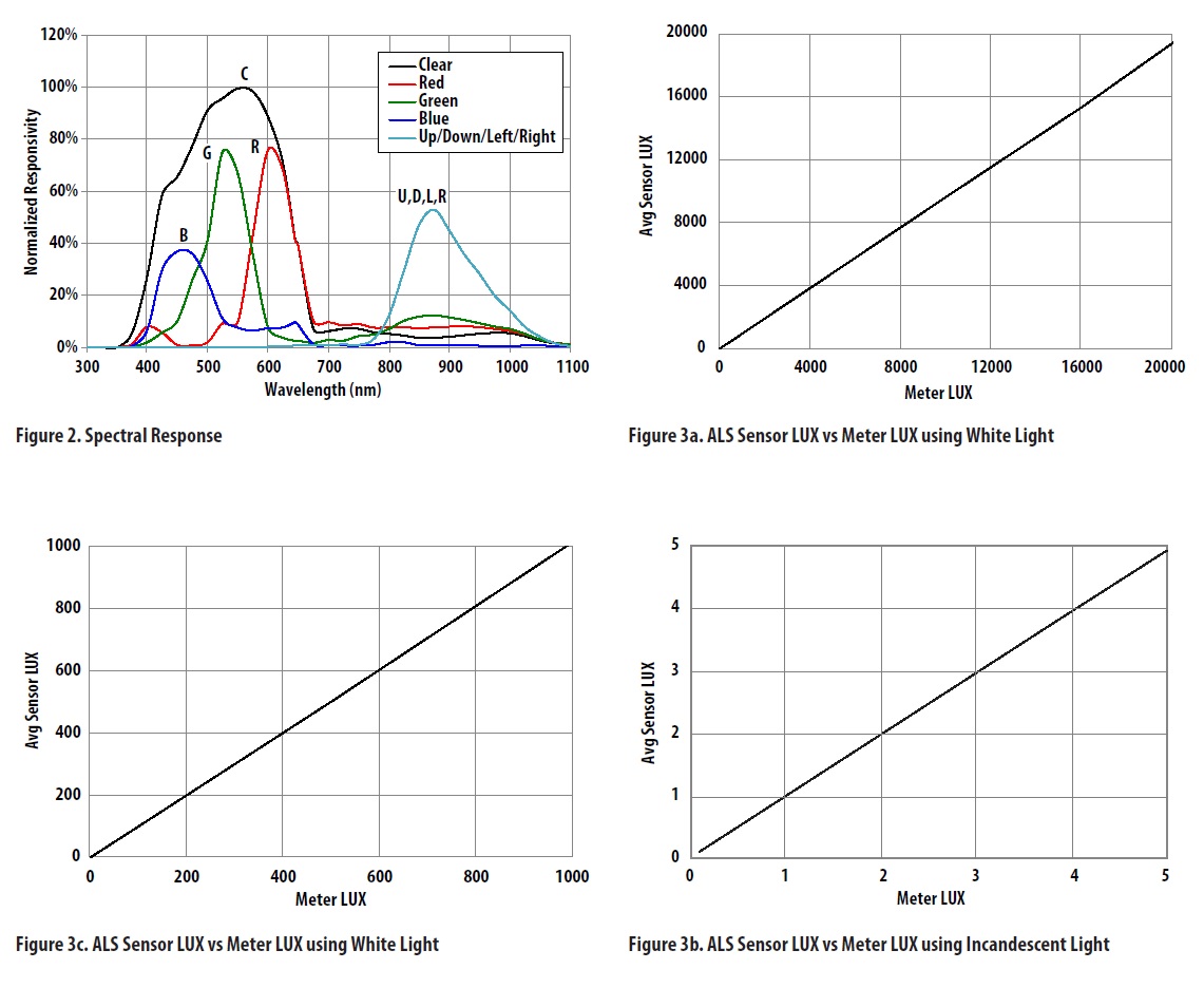
The graphs in the picture above are taken from the documentation on the sensor, the spectral characteristic of Color Sense (RGBC) is shown on the top left.
The photodiode RGBC signal accumulates over a period of time determined by the value of the ATIME register. In SparkFun (in their "apds9960.h"), this value is determined by the constant DEFAULT_ATIME and is equal to 219, which corresponds to 103 ms.
The gain is adjustable from 1x to 64x and is determined by the setting of the CONTROL AGAIN parameter. The constant DEFAULT_AGAIN, equal, in turn, to the value 1, which corresponds to the gain 4 times.
Practical part
Personally, I was only interested in the Color / ALS function in the APDS-9960, so I decided to examine it in more detail and wrote a small code demonstrating its work.
I deliberately tried to make the code as compact, concise and extremely simple to understand as possible; the entire code will be presented at the end of the article.
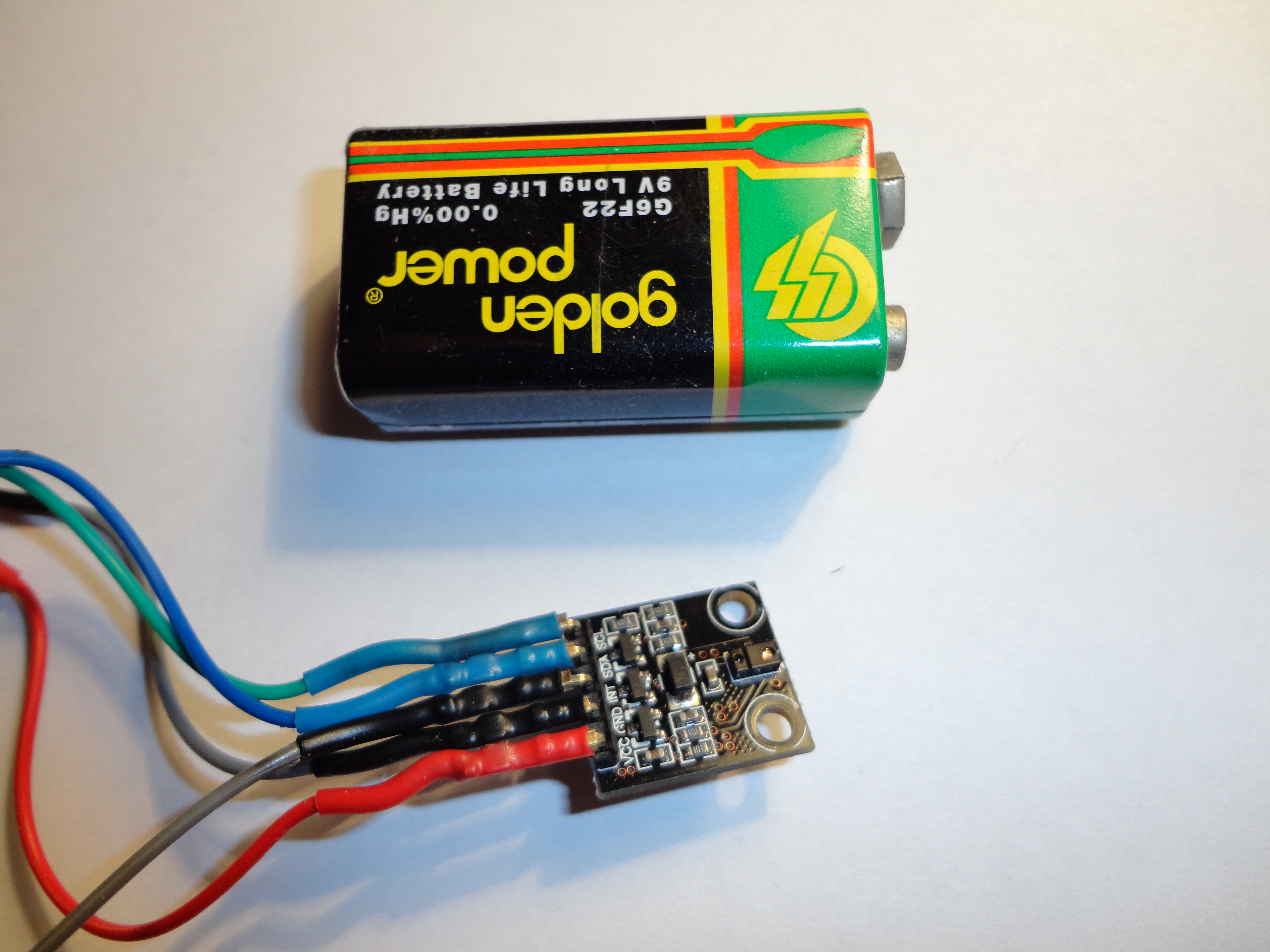
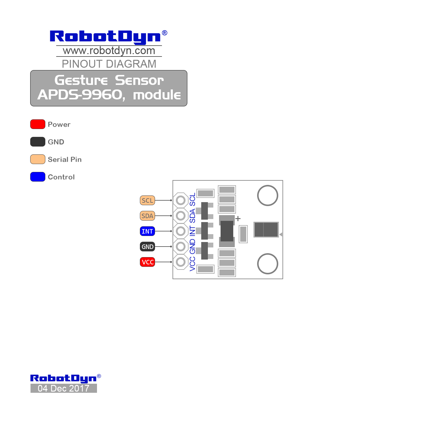
So, all documentation (drawing, pinout and circuit diagram) for the module is available on the manufacturer's website .
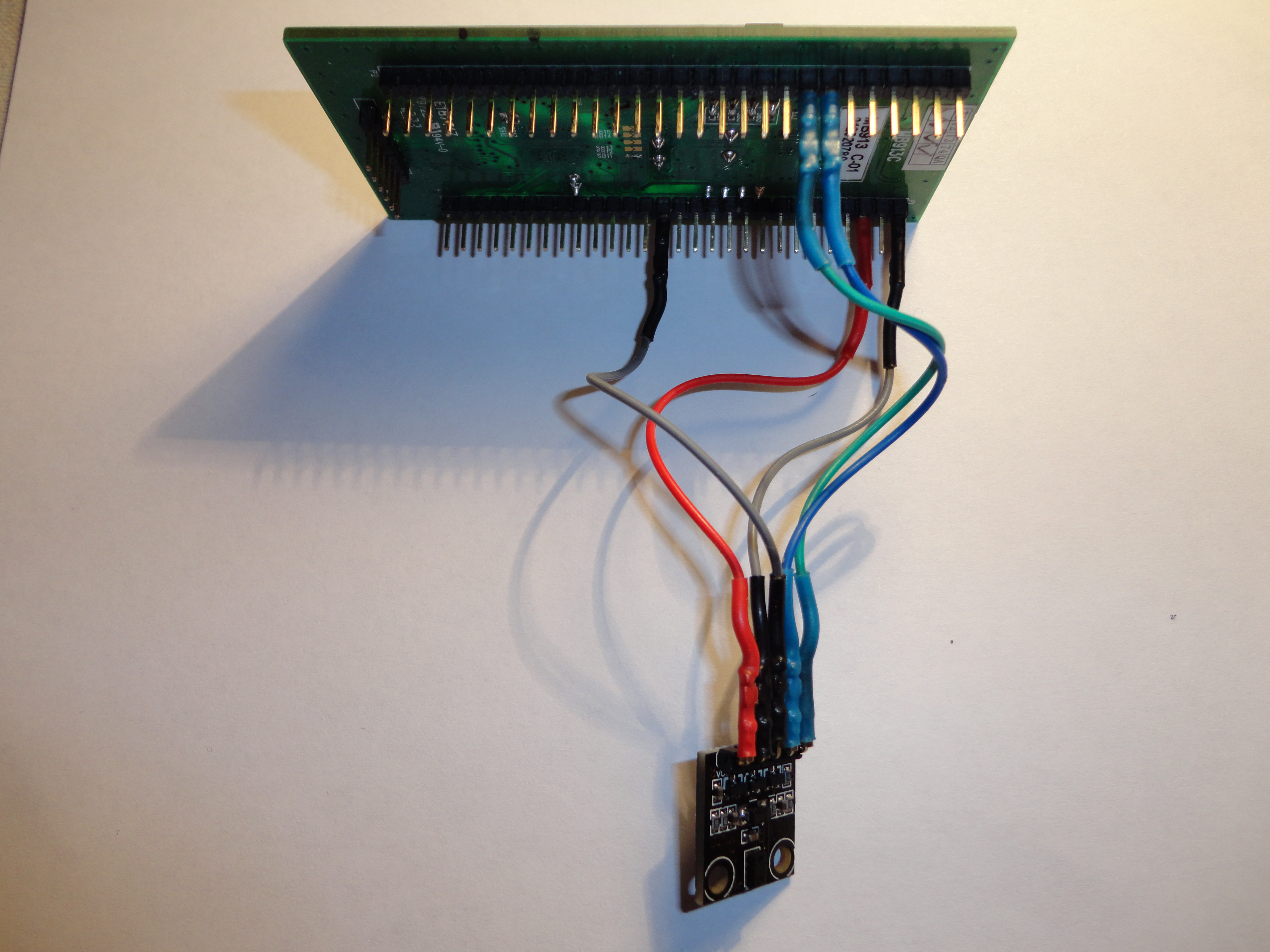
We connect our module APDS-9960 to STM32VLDISCOVERY
The APDS9960 uses the i2c interface to communicate with the outside world, so for STM32VLDISCOVERY, we use the I2C1 bus by connecting the output of the SCL module to the PB6 leg, and the SDA output, respectively, to the PB7 leg. Do not forget to connect the power and common wire. Interrupts will not be used in this case, so the output of Int can not be connected. In my photo it is connected, but not used.
And now a little code. Since all communication with the module is done using i2c, we will create the necessary configuration and define the read / write functions for i2c.
Initialization of I2C.
voidI2C1_init(void){
    I2C_InitTypeDef I2C_InitStructure;
  GPIO_InitTypeDef  GPIO_InitStructure;
  RCC_APB1PeriphClockCmd(RCC_APB1Periph_I2C1, ENABLE);
  RCC_APB2PeriphClockCmd(RCC_APB2Periph_GPIOB| RCC_APB2Periph_AFIO , ENABLE);
    GPIO_InitStructure.GPIO_Speed = GPIO_Speed_2MHz;
    GPIO_InitStructure.GPIO_Mode = GPIO_Mode_AF_OD;
    GPIO_InitStructure.GPIO_Pin = GPIO_Pin_6 | GPIO_Pin_7;
    GPIO_Init(GPIOB, &GPIO_InitStructure);
    I2C_StructInit(&I2C_InitStructure);
    I2C_InitStructure.I2C_ClockSpeed = 100000;
    I2C_InitStructure.I2C_OwnAddress1 = 0x01;
    I2C_InitStructure.I2C_Ack = I2C_Ack_Enable;
    I2C_Init(I2C1, &I2C_InitStructure);
    I2C_Cmd(I2C1, ENABLE);
}
Reading the register.
uint8_t i2c1_read(uint8_t addr)
{
    uint8_t data;
    while(I2C_GetFlagStatus(I2C1, I2C_FLAG_BUSY));
    I2C_GenerateSTART(I2C1, ENABLE);
    while(!I2C_CheckEvent(I2C1, I2C_EVENT_MASTER_MODE_SELECT));
    I2C_Send7bitAddress(I2C1, APDS9960_I2C_ADDR<<1, I2C_Direction_Transmitter);
    while(!I2C_CheckEvent(I2C1, I2C_EVENT_MASTER_TRANSMITTER_MODE_SELECTED));
    I2C_SendData(I2C1, addr);
    while(!I2C_CheckEvent(I2C1, I2C_EVENT_MASTER_BYTE_TRANSMITTED));
    I2C_GenerateSTART(I2C1, ENABLE);
    while(!I2C_CheckEvent(I2C1, I2C_EVENT_MASTER_MODE_SELECT));
    I2C_Send7bitAddress(I2C1, APDS9960_I2C_ADDR<<1, I2C_Direction_Receiver);
    while(!I2C_CheckEvent(I2C1,I2C_EVENT_MASTER_BYTE_RECEIVED));
    data = I2C_ReceiveData(I2C1);
    while(!I2C_CheckEvent(I2C1, I2C_EVENT_MASTER_BYTE_RECEIVED));
    I2C_AcknowledgeConfig(I2C1, DISABLE);
    I2C_GenerateSTOP(I2C1, ENABLE);
    while(I2C_GetFlagStatus(I2C1, I2C_FLAG_BUSY));
    return data;
}
Writing value to register
voidi2c1_write(uint8_t addr, uint8_t data){
    I2C_GenerateSTART(I2C1, ENABLE);
    while(!I2C_CheckEvent(I2C1, I2C_EVENT_MASTER_MODE_SELECT));
    I2C_Send7bitAddress(I2C1, APDS9960_I2C_ADDR<<1, I2C_Direction_Transmitter);
    while(!I2C_CheckEvent(I2C1, I2C_EVENT_MASTER_TRANSMITTER_MODE_SELECTED));
    I2C_SendData(I2C1, addr);
    while(!I2C_CheckEvent(I2C1, I2C_EVENT_MASTER_BYTE_TRANSMITTED));
    I2C_SendData(I2C1, data);
    while(!I2C_CheckEvent(I2C1, I2C_EVENT_MASTER_BYTE_TRANSMITTED));
    I2C_GenerateSTOP(I2C1, ENABLE);
    while(I2C_GetFlagStatus(I2C1, I2C_FLAG_BUSY)) {};
}
In order for the module to work properly, it must first be properly configured. Specifically, for color recognition and lighting it is necessary to do the following:
1) Determine the ATIME register. By default, when the module starts, the ATIME register is set to 0xFF and if nothing is changed, this will affect the sensitivity of the sensor - the sensitivity will be low.
i2c1_write(APDS9960_ATIME, DEFAULT_ATIME);2) the next step is to set the AGAIN parameter field (ALS and Color Gain Control) of the Control Register One register (0x8F) to the value corresponding to the gain equal to x4 (DEFAULT_AGAIN equal to AGAIN_4X).
i2c1_write(APDS9960_CONTROL, DEFAULT_AGAIN);3) enable the ALS option by setting the AEN bit of the Enable Register register (0x80)
4) turn on the module power supply by setting the PON bit of the same register
so here:
i2c1_write(APDS9960_ENABLE, (APDS9960_PON | APDS9960_AEN));That's the whole setup. Our sensor is ready for work and defense, you can begin to measure all the colors.
But first, measure the light level
Colour_tmpL = i2c1_read(APDS9960_CDATAL);
Colour_tmpH = i2c1_read(APDS9960_CDATAH);
Colour_Clear = (Colour_tmpH << 8) + Colour_tmpL;
And now our business has come to the long-awaited flowers
//_________________________________________________________________________// RED color Recognize:
Colour_tmpL = i2c1_read(APDS9960_RDATAL);
Colour_tmpH = i2c1_read(APDS9960_RDATAH);
Colour_Red = (Colour_tmpH << 8) + Colour_tmpL;
//_________________________________________________________________________// GREEN color Recognize:
Colour_tmpL = i2c1_read(APDS9960_GDATAL);
Colour_tmpH = i2c1_read(APDS9960_GDATAH);
Colour_Green = (Colour_tmpH << 8) + Colour_tmpL;
//_________________________________________________________________________// BLUE color Recognize:
Colour_tmpL = i2c1_read(APDS9960_BDATAL);
Colour_tmpH = i2c1_read(APDS9960_BDATAH);
Colour_Blue = (Colour_tmpH << 8) + Colour_tmpL;
And now the whole code:
#include"stm32f10x.h"#define APDS9960_I2C_ADDR       0x39#define APDS9960_ATIME          0x81#define APDS9960_CONTROL        0x8F#define APDS9960_ENABLE         0x80#define APDS9960_CDATAL         0x94#define APDS9960_CDATAH         0x95#define APDS9960_RDATAL         0x96#define APDS9960_RDATAH         0x97#define APDS9960_GDATAL         0x98#define APDS9960_GDATAH         0x99#define APDS9960_BDATAL         0x9A#define APDS9960_BDATAH         0x9B/* Bit fields */#define APDS9960_PON            0x01#define APDS9960_AEN            0x02#define APDS9960_PEN            0x04#define APDS9960_WEN            0x08#define APSD9960_AIEN           0x10#define APDS9960_PIEN           0x20#define APDS9960_GEN            0x40#define APDS9960_GVALID         0x01/* ALS Gain (AGAIN) values */#define AGAIN_1X                0#define AGAIN_4X                1#define AGAIN_16X               2#define AGAIN_64X               3#define DEFAULT_ATIME           219     // 103ms#define DEFAULT_AGAIN           AGAIN_4Xuint8_t Colour_tmpL = 0;
uint8_t Colour_tmpH = 0;
uint16_t Colour_Clear = 0;
uint16_t Colour_Red = 0;
uint16_t Colour_Green = 0;
uint16_t Colour_Blue = 0;
//-----------------------------------------------------------------------voidI2C1_init(void){
    I2C_InitTypeDef I2C_InitStructure;
  GPIO_InitTypeDef  GPIO_InitStructure;
  RCC_APB1PeriphClockCmd(RCC_APB1Periph_I2C1, ENABLE);
  RCC_APB2PeriphClockCmd(RCC_APB2Periph_GPIOB| RCC_APB2Periph_AFIO , ENABLE);
    GPIO_InitStructure.GPIO_Speed = GPIO_Speed_2MHz;
    GPIO_InitStructure.GPIO_Mode = GPIO_Mode_AF_OD;
    GPIO_InitStructure.GPIO_Pin = GPIO_Pin_6 | GPIO_Pin_7;
    GPIO_Init(GPIOB, &GPIO_InitStructure);
    I2C_StructInit(&I2C_InitStructure);
    I2C_InitStructure.I2C_ClockSpeed = 100000;
    I2C_InitStructure.I2C_OwnAddress1 = 0x01;
    I2C_InitStructure.I2C_Ack = I2C_Ack_Enable;
    I2C_Init(I2C1, &I2C_InitStructure);
    I2C_Cmd(I2C1, ENABLE);
}
//-----------------------------------------------------------------------uint8_t i2c1_read(uint8_t addr)
{
    uint8_t data;
    while(I2C_GetFlagStatus(I2C1, I2C_FLAG_BUSY));
    I2C_GenerateSTART(I2C1, ENABLE);
    while(!I2C_CheckEvent(I2C1, I2C_EVENT_MASTER_MODE_SELECT));
    I2C_Send7bitAddress(I2C1, APDS9960_I2C_ADDR<<1, I2C_Direction_Transmitter);
    while(!I2C_CheckEvent(I2C1, I2C_EVENT_MASTER_TRANSMITTER_MODE_SELECTED));
    I2C_SendData(I2C1, addr);
    while(!I2C_CheckEvent(I2C1, I2C_EVENT_MASTER_BYTE_TRANSMITTED));
    I2C_GenerateSTART(I2C1, ENABLE);
    while(!I2C_CheckEvent(I2C1, I2C_EVENT_MASTER_MODE_SELECT));
    I2C_Send7bitAddress(I2C1, APDS9960_I2C_ADDR<<1, I2C_Direction_Receiver);
    while(!I2C_CheckEvent(I2C1,I2C_EVENT_MASTER_BYTE_RECEIVED));
    data = I2C_ReceiveData(I2C1);
    while(!I2C_CheckEvent(I2C1, I2C_EVENT_MASTER_BYTE_RECEIVED));
    I2C_AcknowledgeConfig(I2C1, DISABLE);
    I2C_GenerateSTOP(I2C1, ENABLE);
    while(I2C_GetFlagStatus(I2C1, I2C_FLAG_BUSY));
    return data;
}
//-----------------------------------------------------------------------voidi2c1_write(uint8_t addr, uint8_t data){
    I2C_GenerateSTART(I2C1, ENABLE);
    while(!I2C_CheckEvent(I2C1, I2C_EVENT_MASTER_MODE_SELECT));
    I2C_Send7bitAddress(I2C1, APDS9960_I2C_ADDR<<1, I2C_Direction_Transmitter);
    while(!I2C_CheckEvent(I2C1, I2C_EVENT_MASTER_TRANSMITTER_MODE_SELECTED));
    I2C_SendData(I2C1, addr);
    while(!I2C_CheckEvent(I2C1, I2C_EVENT_MASTER_BYTE_TRANSMITTED));
    I2C_SendData(I2C1, data);
    while(!I2C_CheckEvent(I2C1, I2C_EVENT_MASTER_BYTE_TRANSMITTED));
    I2C_GenerateSTOP(I2C1, ENABLE);
    while(I2C_GetFlagStatus(I2C1, I2C_FLAG_BUSY)) {};
}
//-----------------------------------------------------------------------intmain(){
    I2C1_init();
    i2c1_write(APDS9960_ATIME, DEFAULT_ATIME);
    i2c1_write(APDS9960_CONTROL, DEFAULT_AGAIN);
    i2c1_write(APDS9960_ENABLE, (APDS9960_PON | APDS9960_AEN));
  while (1)
  {
            Colour_Clear = 0;
            Colour_Red = 0;
            Colour_Green = 0;
            Colour_Blue = 0;
        //_________________________________________________________________________// Ambient Light Recognize:
            Colour_tmpL = i2c1_read(APDS9960_CDATAL);
            Colour_tmpH = i2c1_read(APDS9960_CDATAH);
            Colour_Clear = (Colour_tmpH << 8) + Colour_tmpL;
        //_________________________________________________________________________// RED color Recognize:
            Colour_tmpL = i2c1_read(APDS9960_RDATAL);
            Colour_tmpH = i2c1_read(APDS9960_RDATAH);
            Colour_Red = (Colour_tmpH << 8) + Colour_tmpL;
        //_________________________________________________________________________// GREEN color Recognize:
            Colour_tmpL = i2c1_read(APDS9960_GDATAL);
            Colour_tmpH = i2c1_read(APDS9960_GDATAH);
            Colour_Green = (Colour_tmpH << 8) + Colour_tmpL;
        //_________________________________________________________________________// BLUE color Recognize:
            Colour_tmpL = i2c1_read(APDS9960_BDATAL);
            Colour_tmpH = i2c1_read(APDS9960_BDATAH);
            Colour_Blue = (Colour_tmpH << 8) + Colour_tmpL;
    }
}
I intentionally did not make the definitions of the constants in a separate heder for convenience.
Constants, by the way, borrowed from the official repository of SparkFun Electronics. Here here .
I liked the APDS-9960 very much - an interesting thing, it was interesting to explore, it was interesting to write an article. I hope someone this material will be useful. Thanks for attention.