May 26, 2014 at 14:26
nanoCAD Plus 6.0: new and improved
More than 2 thousand hours of testing, more than 500 corrections and improvements, 23 innovations (of which 10 are very powerful) - these dry numbers are followed by one year of our work and the release of an updated (no doubt significantly more powerful) version of the Russian CAD platform nanoCAD Plus 6.0. Are we proud of this event? Of course! We are almost 6 years old and all this time we constantly increase the functionality of our brainchild. We are not just developing, but also actively expanding the user base - we already have half a million users! In our opinion, nanoCAD is a worthy response to Western CAD; an example of real import substitution, which is talked about so much today.

Those who are in the know - can immediately go to the download page of the new version in the torrent network or on our website. And who are interested in the details - welcome to kat; We will tell about innovations.
Accordingly, with the release of the sixth version, we also rename the Russian-language versions of the products, leading them to the same denominator. From now on, the free version of the nanoCAD platform will simply be called nanoCAD (instead of nanoCAD free, and thus we emphasize our initial idea that nanoCAD is initially a free software product), and the advanced version, which has powerful functionality for automating project work, will be called nanoCAD Plus The word "Plus" emphasizes that the user receives an additive compared to the free version, an advantage that is worth the finances invested in the software product.
So what will you find in the sixth version of nanoCAD Plus?
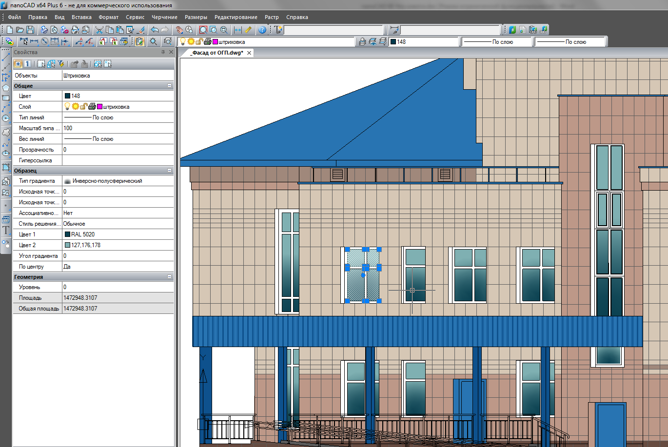
In addition, we have implemented the functionality of constructing gradient hatching, which architecture departments and designers who create presentation drawings love so much. Now a new Gradient command appears in the Drawing menu, which allows you to specify the transition from one color to another (Fig. 1).
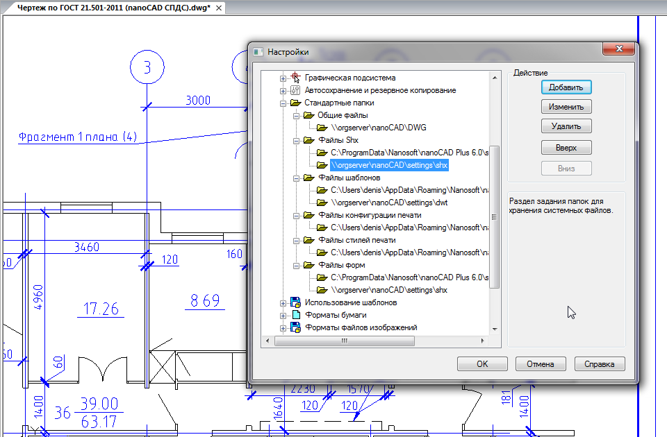
The new version of nanoCAD allows you to specify additional standard folders (which may also be network folders) in the program settings, and the program will take these directories into account when searching for working files. Thus, setting up the nanoCAD environment is greatly simplified (Fig. 2).
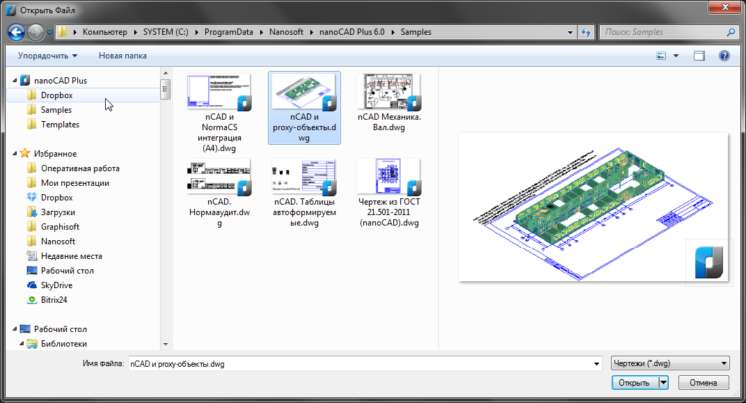
This functionality has another small but convenient innovation: you can add links to any set of external folders and directories to the standard dialogs Open, Save and Save as ... By default, we display the folders of examples and templates, but by adding our directories in the Service \ Settings \ General files dialog (for example, the department folder on the organization’s server), we will see them in the Open dialog (Fig. 3). Plus, you can turn on the Open preview mode dialog box and see the contents of the file.
In addition, the list of shared folders in the upper list of the Open dialog will dynamically adapt to the type of file being opened - for example:
Nevertheless, using the SCALEUNITS variable, users can control the displayed list of scales - for example, the value of variable 1 and 2 includes the output of inch scales, which allows using nanoCAD for any projects.
At any time, users can expand the list of scales by updating the nCAD.ini files from the% nanoCAD% folder (scales of the SE and the print dialog) and settings.xml from the% ALLUSERSPROFILE% folder (scales of annotation objects).
To work with raster images in nanoCAD, a separate menu is selected, in which there are a lot of useful functions. Starting from version 6.0, this menu has been expanded with a new group of commands for creating raster images and rasterizing (that is, converting from a vector format to a raster) data of a * .dwg drawing (Fig. 4).
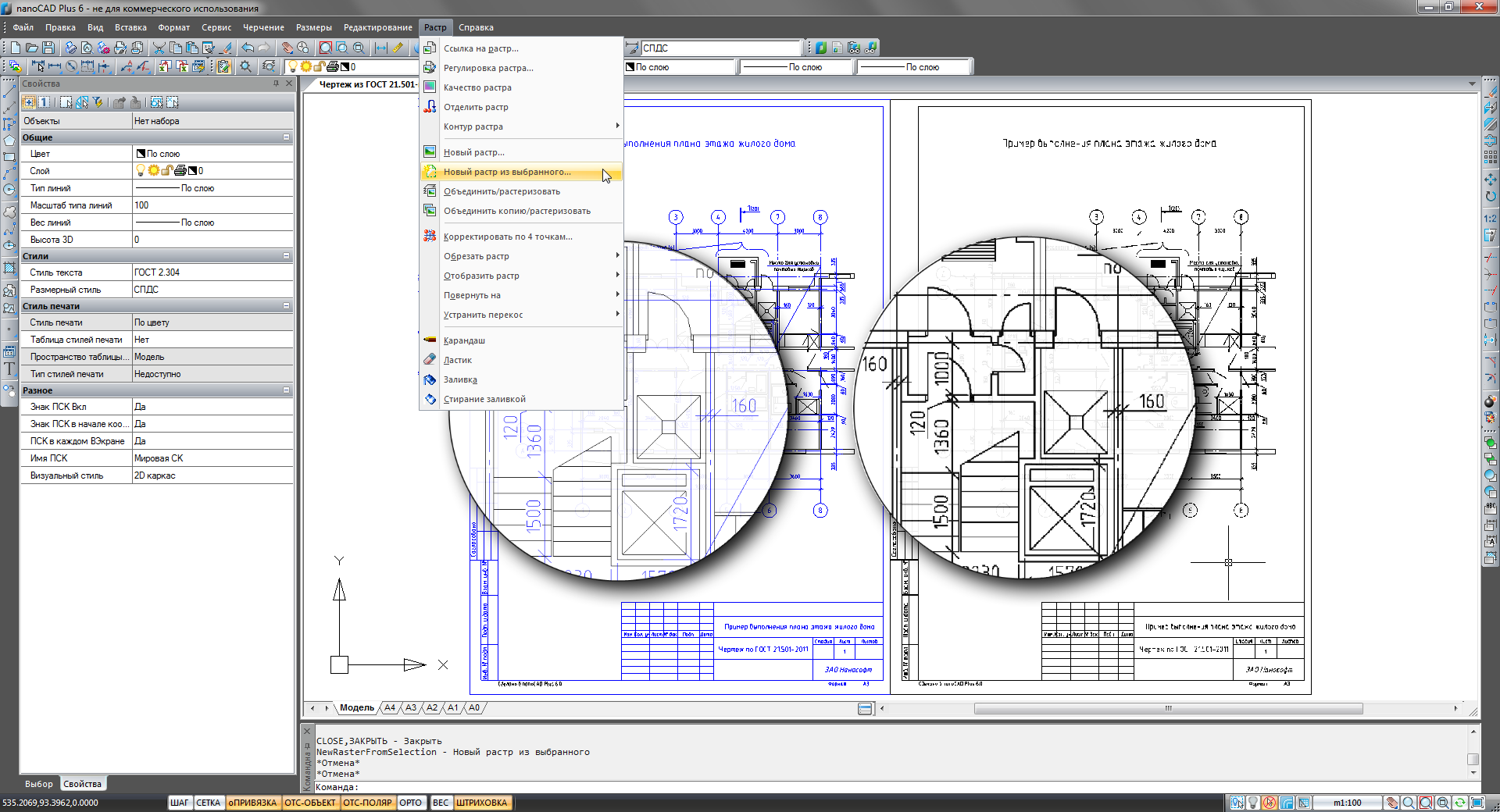
The functionality is very powerful and, perhaps, somewhat complicated for novice users. But in skilled hands, it allows you to simply perform miracles - completely control the quality of the created raster, format (jpg, tif, pcx, png, bmp), color, etc.
Together with the new function that enabled the implementation of raster images inside a * .dwg drawing (see the External Links dialog), the rasterization function allows you to instantly receive a raster * .dwg drawing that can be transferred to the customer painlessly and be sure that the data on the drawing will not modified without your knowledge.
After describing this function, we gradually come to the description of a unique functional that you will not find in other CAD systems.
Why not develop a feature that automates the validation of links to regulatory documents? And in nanoCAD Plus 6.0 we implemented the Normaaudit function: we click on the button and nanoCAD analyzes all textual entries in the * .dwg drawing, compiles a list of links to regulatory documents and, using the regularly updated NormaCS database, sorts these links by status (valid, not valid, in a project state, etc.), types of document (GOST, SNiP, SP, TU, etc.) (Fig. 5). Now you have all the controversial documents at a glance - we have added convenient means of navigating the drawing (auto-enlargement, underline, transition to the next link) and work with such a list. For example, with one click you can open a scan or a vector analogue of a document in NormaCS!
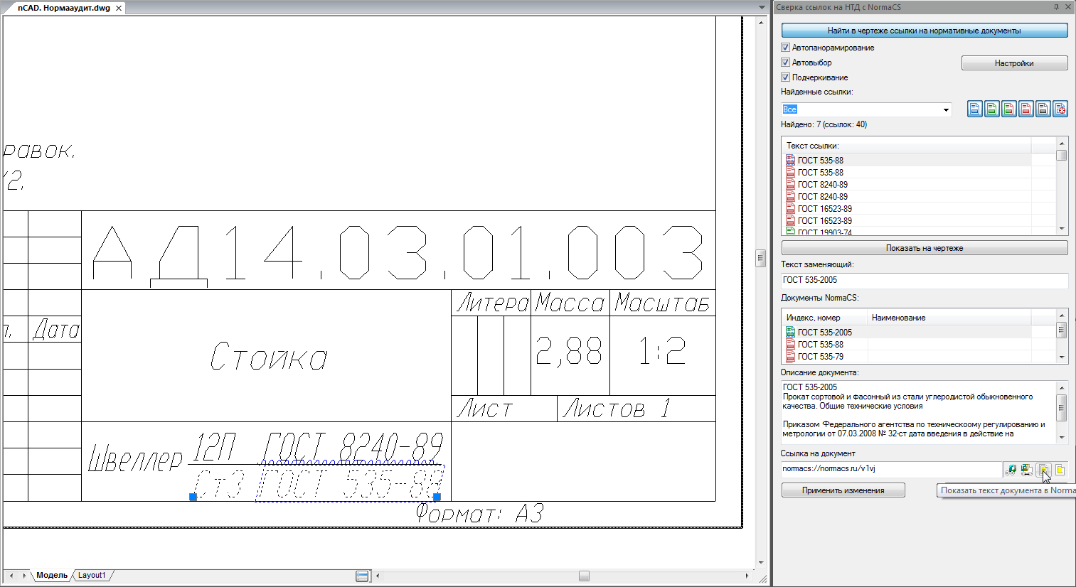
To take full advantage of the Normaaudit function, it is better to have a regularly updated version of NormaCS on your computer - either a local copy or a network copy in your organization. But we also envisioned a situation where for some reason you do not have a fresh version of NormaCS - in this case, a small NormaCS client is installed on your computer with nanoCAD, which will contact the cloudy, latest version of the regulatory documents library. Of course, you will not receive the texts of the documents themselves, but the card of the document, its status and all comments related to this document will be at your disposal.
An excellent tool not only for standard controllers, but also for those designers who care about the quality of their projects and the documentation being developed.
Nevertheless, in the new version, we are taking the next step towards the development of a convenient and understandable printing system - see Fig. 6 is our updated print dialog.

Now the print dialog is similar to a real printing processor and allows you to visually conduct operations on the optimal placement of the drawing on a sheet of paper. For example, choosing a paper format and a plotter, we can precisely align the image, having before our eyes a physical sheet of paper with dimensions, orientation and print margins. And, therefore, we can print either by pressing the drawing to the physical edge of the sheet, or taking into account the plot area of the plotter. In addition, you can expand the drawing on a sheet and thus reduce paper consumption if the drawing is displayed on rolls. A clear plotter icon in the upper corner will show how the paper will exit the plotter and where on a long roll we should expect our drawing.
In the same dialog, you can switch to the full preview screen and see how print styles are applied to the document. New print areas, number of copies, output scale, print quality and other parameters that are already responsible for physical printing are immediately set. And all this in one relatively simple dialogue, which we also plan to develop further - there is an idea to fully solve the problem of laying out drawings on a sheet.

The drawing manager allows you to not only understand what objects the * .dwg file is saturated with, but also quickly find them on the drawing, select, zoom in and, for example, delete them. Separately, all drawing proxies are collected, and, thanks to the expansion of the Properties window, selected proxy objects tell you in which CAD systems they were created. All blocks, external links, raster substrates collected in the current document, layers, text and dimensional styles, named views, sheets are clearly displayed.
But in general, the Drawing Manager should also be classified as unique functions thanks to the tool to reduce the list of drawing objects. The fact is that the Drawing Manager can dynamically display a change in the structure of a * .dwg file! A complete list of objects can be reduced by a filter to newly created or updated objects as part of the last file editing session. Once, and you only display what was created by you - isn't it beautiful? Complete control over changes to important drawings at your fingertips!
In general, it turned out to be an excellent tool for analyzing * .dwg documents, which can be developed and saturated with additional service functions - we are waiting for your feedback and suggestions.
In the new version of nanoCAD, we expanded this menu item with another unique utility - Geometry Check (PROGE), which currently solves problems with two types of files:
In general, the appearance of a utility for checking geometry is the first and very important step of the nanoCAD platform towards improving the quality of * .dwg files on the market. We plan to further develop the functionality of this utility, so we are waiting for your suggestions and problem files.
Without a doubt, the new version of nanoCAD will be of interest to most CAD users and will help in solving everyday design problems. Visit us at nanocad.ru , download demos, perform functional and price analysis of nanoCAD Plus and its competitors, and choose the tool that provides the best price-quality ratio.
Good projects for you - and we are waiting for you among our users!
Those who are in the know - can immediately go to the download page of the new version in the torrent network or on our website. And who are interested in the details - welcome to kat; We will tell about innovations.
Introduction: rebranding and new entities
Everyone who closely follows the nanoCAD project sees that changes occur every year and more than once. The project is living through a period of very rapid growth. This is due to the fact that we are constantly looking for the most understandable and convenient forms and entities, trying to convey to the world our idea and purpose of existence. When the English version appeared, we entered the market with slightly changed product names - instead of a pair of nanoCAD free and nanoCAD, as it was on the Russian-speaking market, we released the nanoCAD and nanoCAD Plus software products. From our point of view, these names better reflect the technical essence of software products and convey the idea of an expanded version of the platform, on the basis of which all vertical software products are built.Accordingly, with the release of the sixth version, we also rename the Russian-language versions of the products, leading them to the same denominator. From now on, the free version of the nanoCAD platform will simply be called nanoCAD (instead of nanoCAD free, and thus we emphasize our initial idea that nanoCAD is initially a free software product), and the advanced version, which has powerful functionality for automating project work, will be called nanoCAD Plus The word "Plus" emphasizes that the user receives an additive compared to the free version, an advantage that is worth the finances invested in the software product.
So what will you find in the sixth version of nanoCAD Plus?
Development of generally accepted CAD functionality
We begin our review with the functionality that develops nanoCAD to serious CAD - in the sixth version we included the next pool of long-awaited functions.Hatching Development: Gradient and Cropping
The functionality for cutting hatching can be called the most long-awaited - unfortunately, the complexity of the algorithms did not allow to release it in the first versions. In order for this function to work honestly, it was necessary to take into account the hatching not only with standard primitives such as segments and circles, but also the splitting by splines, it was necessary to teach hatching not to lose associativity and the rules for constructing complex configurations with islands. Analyzing the new version, our test lab decided to let the new functionality into the light of the judgment of our users.In addition, we have implemented the functionality of constructing gradient hatching, which architecture departments and designers who create presentation drawings love so much. Now a new Gradient command appears in the Drawing menu, which allows you to specify the transition from one color to another (Fig. 1).
Рис. 1. В nanoCAD 6.0 появилась градиентная штриховка, которая позволяет создавать презентационные чертежиMultiline Tool
The Multiline tool (MINE, MLINE), well known since 2008, also appeared in nanoCAD Plus 6.0. Now with the help of one command you can create a set of parallel lines, thus drawing the lines of roads, pipelines, walls, etc. At the same time, nanoCAD allows you to create new styles of multilines, load them from external mln files, use them when searching, include them in tabular reports - that is, perform a wide range of operations with objects.ETransmit Team
Another team from the category of "necessary". The eTransmit command allows you to collect all the data included in the current drawing (shx fonts, external links, bitmap substrates, etc.) and save them as a single zip file. Then this single project file is sent to the customer, colleagues, in the archive and is guaranteed to be opened on another computer without any problems.Additional "Standard Folders"
The functionality of standard folders is necessary in order to “sharpen" the CAD platform for the standards of organizations: the folders contain templates, fonts, standard line types, hatching, styles and print configurations, which are used by designers for work. It is very important to use uniform settings throughout the organization - then there will be no problems with displaying drawings at different workstations. Previously, nanoCAD used only one type of folder - the ones that it installed on the computer by default. And if you needed to expand the list of standard settings (for example, add a set of “your” fonts to the standard ones), then you had to copy additional files to the nanoCAD folder. It is not difficult when CAD is used at 1-2 workplaces. If you have 100 or more computers at your disposal,The new version of nanoCAD allows you to specify additional standard folders (which may also be network folders) in the program settings, and the program will take these directories into account when searching for working files. Thus, setting up the nanoCAD environment is greatly simplified (Fig. 2).
Рис. 2. Возможность задавать дополнительные стандартные папки существенно упрощает настройку nanoCAD для использования в корпоративной средеThis functionality has another small but convenient innovation: you can add links to any set of external folders and directories to the standard dialogs Open, Save and Save as ... By default, we display the folders of examples and templates, but by adding our directories in the Service \ Settings \ General files dialog (for example, the department folder on the organization’s server), we will see them in the Open dialog (Fig. 3). Plus, you can turn on the Open preview mode dialog box and see the contents of the file.
Рис. 3. Общие директории отображаются в группе nanoCAD Plus диалога Открыть – найти *.dwg-файлы во внешних папках стало прощеIn addition, the list of shared folders in the upper list of the Open dialog will dynamically adapt to the type of file being opened - for example:
- if you add a new type of lines to the program, then at the top of the dialog you will find the SHX folder, which you will enter in one click;
- if you create a new document based on a template and request it at startup, the quick links section of the dialog will display the templates folder;
- etc.
Scales according to GOST 2.302-68
When working with documentation, designers constantly use scales - they are used when setting up annotation elements (texts, callouts, sizes, tables, etc.), when placing viewports on sheets, and when printing documentation. In the new version of nanoCAD, we standardized the scales used in CAD, including the default metric scales for the Russian version, corresponding to GOST 2.302-68.Nevertheless, using the SCALEUNITS variable, users can control the displayed list of scales - for example, the value of variable 1 and 2 includes the output of inch scales, which allows using nanoCAD for any projects.
At any time, users can expand the list of scales by updating the nCAD.ini files from the% nanoCAD% folder (scales of the SE and the print dialog) and settings.xml from the% ALLUSERSPROFILE% folder (scales of annotation objects).
Screening Functionality
Periodically, designers need to transfer customer drawings in an uneditable format. The most convenient of them is a bitmap image, which then can only be changed in editors such as Adobe Photoshop. And if in systems such as AutoCAD, raster images are created by printing to a virtual printer, then in nanoCAD the path is slightly different.To work with raster images in nanoCAD, a separate menu is selected, in which there are a lot of useful functions. Starting from version 6.0, this menu has been expanded with a new group of commands for creating raster images and rasterizing (that is, converting from a vector format to a raster) data of a * .dwg drawing (Fig. 4).
Рис. 4. Меню Растр в nanoCAD Plus 6.0 расширилось командами для создания растровых изображений внутри *.dwg-чертежа и растеризации векторных изображенийThe functionality is very powerful and, perhaps, somewhat complicated for novice users. But in skilled hands, it allows you to simply perform miracles - completely control the quality of the created raster, format (jpg, tif, pcx, png, bmp), color, etc.
Together with the new function that enabled the implementation of raster images inside a * .dwg drawing (see the External Links dialog), the rasterization function allows you to instantly receive a raster * .dwg drawing that can be transferred to the customer painlessly and be sure that the data on the drawing will not modified without your knowledge.
After describing this function, we gradually come to the description of a unique functional that you will not find in other CAD systems.
Unique nanoCAD Plus 6.0 functionality
Normaaudit function
When developing working documentation, designers constantly refer to standards and normative documentation. Moreover, these links are made out in the form of separate texts (single-line or multi-line) in tables, texts of explanatory notes, stamps, callouts, blocks, etc. Often, pieces of old or standard documentation are added to existing documentation. At the same time, standards, norms are constantly updated, changed, improved. Not surprisingly, a link to an outdated document may appear in the document.Why not develop a feature that automates the validation of links to regulatory documents? And in nanoCAD Plus 6.0 we implemented the Normaaudit function: we click on the button and nanoCAD analyzes all textual entries in the * .dwg drawing, compiles a list of links to regulatory documents and, using the regularly updated NormaCS database, sorts these links by status (valid, not valid, in a project state, etc.), types of document (GOST, SNiP, SP, TU, etc.) (Fig. 5). Now you have all the controversial documents at a glance - we have added convenient means of navigating the drawing (auto-enlargement, underline, transition to the next link) and work with such a list. For example, with one click you can open a scan or a vector analogue of a document in NormaCS!
Рис. 5. Уникальная среди САПР функция Нормааудит позволяет получить список ссылок на нормативные документы и определить статус каждого найденного документаTo take full advantage of the Normaaudit function, it is better to have a regularly updated version of NormaCS on your computer - either a local copy or a network copy in your organization. But we also envisioned a situation where for some reason you do not have a fresh version of NormaCS - in this case, a small NormaCS client is installed on your computer with nanoCAD, which will contact the cloudy, latest version of the regulatory documents library. Of course, you will not receive the texts of the documents themselves, but the card of the document, its status and all comments related to this document will be at your disposal.
An excellent tool not only for standard controllers, but also for those designers who care about the quality of their projects and the documentation being developed.
Printing: developing a simpler and more visual process
Is it possible to make the printing process in CAD simple and intuitive? A philosophical question, given that wide-format printing devices do not have a standard for communicating with programs, they have different technical characteristics (for example, print fields), settings (for example, spread, alignment rules) and even a data description language.Nevertheless, in the new version, we are taking the next step towards the development of a convenient and understandable printing system - see Fig. 6 is our updated print dialog.
Рис. 6. Новый диалог Печать nanoCAD Plus 6.0 предоставляет пользователям наглядный способ вывода документации на печать: выравнивание чертежа относительно листа, разворот изображения для оптимизации расхода бумаги, подбор подходящего формата бумаги и т.д.Now the print dialog is similar to a real printing processor and allows you to visually conduct operations on the optimal placement of the drawing on a sheet of paper. For example, choosing a paper format and a plotter, we can precisely align the image, having before our eyes a physical sheet of paper with dimensions, orientation and print margins. And, therefore, we can print either by pressing the drawing to the physical edge of the sheet, or taking into account the plot area of the plotter. In addition, you can expand the drawing on a sheet and thus reduce paper consumption if the drawing is displayed on rolls. A clear plotter icon in the upper corner will show how the paper will exit the plotter and where on a long roll we should expect our drawing.
In the same dialog, you can switch to the full preview screen and see how print styles are applied to the document. New print areas, number of copies, output scale, print quality and other parameters that are already responsible for physical printing are immediately set. And all this in one relatively simple dialogue, which we also plan to develop further - there is an idea to fully solve the problem of laying out drawings on a sheet.
Development of support for * .dwg format
Format * .dwg ... How much in this sound for the developer nanoCAD merged! The more popular nanoCAD gains, the more interesting drawings are sent to us - in recent years we have come across huge general plans and drawings destroyed in z-coordinate (after ZWCAD). Documents came with lost Russian code pages, and strange contours of hatching that were drawn in an area the size of a needle’s eye (after CREDO). We actively analyzed all such drawings, improved the internal algorithms of nanoCAD tools, learned to take into account features and work around problems. And in parallel, we had the idea to create a tool for analyzing * .dwg formats.Drawing manager
And now in version 6.0 we present the new Drawing Manager tool, which in the form of a tree displays the entire internal structure of the current open * .dwg file (Fig. 7).Рис. 7. Новый инструмент Диспетчер чертежей позволяет лучше понять внутреннюю структуру *.dwg-файла: количество объектов, атрибутов, видов и т.д.The drawing manager allows you to not only understand what objects the * .dwg file is saturated with, but also quickly find them on the drawing, select, zoom in and, for example, delete them. Separately, all drawing proxies are collected, and, thanks to the expansion of the Properties window, selected proxy objects tell you in which CAD systems they were created. All blocks, external links, raster substrates collected in the current document, layers, text and dimensional styles, named views, sheets are clearly displayed.
But in general, the Drawing Manager should also be classified as unique functions thanks to the tool to reduce the list of drawing objects. The fact is that the Drawing Manager can dynamically display a change in the structure of a * .dwg file! A complete list of objects can be reduced by a filter to newly created or updated objects as part of the last file editing session. Once, and you only display what was created by you - isn't it beautiful? Complete control over changes to important drawings at your fingertips!
In general, it turned out to be an excellent tool for analyzing * .dwg documents, which can be developed and saturated with additional service functions - we are waiting for your feedback and suggestions.
Work with problem files
Nevertheless, the task of correcting the structure of a * .dwg file constantly faces experienced CAD users and services that ensure the efficiency of design organizations. Such users are well aware of Document Verification (AUDIT), Document Recovery (RECOVER) and Drawing Cleanup (PURGE) utilities - all of them are located in the File \ Utilities menu.In the new version of nanoCAD, we expanded this menu item with another unique utility - Geometry Check (PROGE), which currently solves problems with two types of files:
- The option Check z-coordinates analyzes the z-coordinates of the drawing and, if it detects a violation of the geometry integrity (for example, objects are scattered along the z-height in the range of plus or minus 20 million units), suggests correcting the z-coordinates of such objects;
- The Hatch Check option checks and recalculates the hatch contours in the drawing, which in some cases eliminates problems with the correct display or hatch spill.
In general, the appearance of a utility for checking geometry is the first and very important step of the nanoCAD platform towards improving the quality of * .dwg files on the market. We plan to further develop the functionality of this utility, so we are waiting for your suggestions and problem files.
Conclusion
In general, nanoCAD Plus has a lot of innovations! I did not talk about the development of the status bar, in which you can now quickly turn off / on the isolation of objects, dynamic highlighting, and manage an option that allows you to select objects on locked layers. I did not talk about the development of the external links dialog, in which, at the request of users, the ability to edit paths to files manually is implemented. I did not talk about various small improvements such as the ability to quickly specify fractional expressions in the MTEXT editor and the ability to separately set the weight of the text and the weight of lines for leader lines (the latter is very much asked by specialists in the general plan departments). I did not talk about the Quick Selection panel, which in the new version can hang in the background and reconfigure object selections on the fly, without interrupting the drawing process ... I have not presented half of all the innovations of the nanoCAD Plus 6.0 platform. Therefore, I hope that many CAD bloggers will pick up my undertaking and conduct a more in-depth analysis of our product, publishing their reviews, analytics, tests, etc. interesting things - all improvements and innovations are described in the documentation that is supplied electronically with the product.Without a doubt, the new version of nanoCAD will be of interest to most CAD users and will help in solving everyday design problems. Visit us at nanocad.ru , download demos, perform functional and price analysis of nanoCAD Plus and its competitors, and choose the tool that provides the best price-quality ratio.
Good projects for you - and we are waiting for you among our users!