Testing a home robot version 0.3.1
Testing the automatic motion mode of a home robot based on data from an infrared, ultrasonic rangefinder and encoders.
This article is a continuation of the previous Review of the home robot ver 0.3 .
The idea is to make a robot able to independently move around the house without human intervention. About the selected chassis platform is described in a previous article. In the process of implementation and testing, a more or less acceptable obstacle detection system was found, which I will discuss below.
It is based on a locator, so to speak - rangefinders rotating on a micro servo.

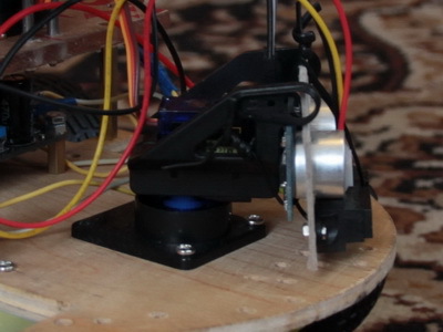
Infrared rangefinder SHARP GP2Y0A41SKOF, it is stated that it measures at a distance of 4x to 30 centimeters. In reality, it can measure further, but with a greater error. When an obstacle is up to 4 centimeters, it gives distorted data, as if the obstacle is further away. The beam sector is small.

From the following graph, you can roughly understand the dependence of the signal on distance.

Test code for the SHARP GP2Y0A41SKOF rangefinder.
#define pin A1
void setup () {
        Serial.begin (9600);
        pinMode(pin, INPUT);
}
void loop () {
        uint16_t value = analogRead (pin);
        double distance = get_ GP2Y0A41SKOF (value); //вычисление на основе аналогового значения расстояния в сантиметрах
        Serial.println (value);
        Serial.print (distance);
        Serial.println (" cm");
        Serial.println ();
        delay (500);
}
//return distance (cm)
double get_ GP2Y0A41SKOF (uint16_t value) {
        if (value < 16)  value = 16;
        return 2076.0 / (value - 11.0);
}
Ultrasonic rangefinder HC-SR04, it is stated that it measures at a distance of 2 to 450 centimeters. The measurement sector is large, depending on the side, ranges from 30 to 60 degrees. The distance calculation is linear, the time of the reflected sound is divided by the speed of sound.

Sample code for the HC-SR04 rangefinder.
digitalWrite(Trig, HIGH); // Подаем сигнал на выход микроконтроллера
delayMicroseconds(10); // Удерживаем 10 микросекунд
digitalWrite(Trig, LOW); // Затем убираем
time_us=pulseIn(Echo, HIGH); // Замеряем длину импульса
distance_sm=time_us/58; // Пересчитываем в сантиметры
Serial.println(distance_sm); // Выводим на порт
Moreover, for the pulseIn function, you can set the time for maximum signal wait, otherwise, in the absence of a reflected sound wave, it can wait a long time blocking the execution of the program, I experimentally set the following value
time_us=pulseIn(Echo, HIGH,50000);It must also be said that, depending on the surface of the obstacle and the angle of reflection, rangefinders can lie a lot. The use of two rangefinders with different types in one direction helps to improve measurement accuracy. At the moment, I am primarily guided by the data from the infrared rangefinder, when it fails, I take data from the ultrasound.
Serva rotates rangefinders from 30 to 150 degrees in increments of 30 degrees, the numbers are taken empirically for speed measurements and simplicity. The measurements are stored in an array and upon request, at any time, a check can be made for obstacles in the rectangular area in front of the robot.
Since the robot often for one reason or another did not detect obstacles, he decided to determine that the robot crashed and could not continue to move according to data from encoders installed on the wheel shaft.
Here are the encoders.


The mechanism of their action is simple; an optical sensor is installed there for the clearance of holes in the disk. I hung the sensor changes to arduino interrupts, below is an example code:
void LwheelSpeed()
{
  coderLeft++;  //count the left wheel encoder interrupts
}
void setup()
 {
  attachInterrupt(LEFT, LwheelSpeed, CHANGE);
}
About once every 200 milliseconds, the wheel speed is calculated. Accordingly, if the speed of the wheels drops significantly during movement, then it is believed that the robot collided with an obstacle. After that, he pulls back and turns around.
Such a non-cunning sensor system achieves an almost one hundred percent guarantee of detection of obstacles. In the video you can watch how the robot fulfills all these situations.
Now I'm waiting for the microswitches and finish the 3d printer, I will make the robot a bumper. Then I think it will work out almost all possible situations.
Several photos of the robot from different angles.


I open an open source project for this robot, as I finish the robot to a more or less sane state, I will lay out the design diagram and source code, if anyone needs to write in a personal message right now.
For more information, news, photos and videos, see the VKontakte group for this project - vk.com/club23358759
Write in the comments on which topic write the next article, shoot a video.