Hack nooLite wireless light control
Hello!
In our previous article, we showed how our controller for home automation works with devices of the NooLite system without using native USB dongles for transmitting and receiving signals. To make this possible, we reverse engineered the NooLite protocol.
Actually, this article contains a description of the protocol and tells how we analyzed it.
Introduction
About a NooLite system on a habr wrote a lot before. The system consists of wireless remotes and actuators that operate at a frequency of 433.92 MHz.
Communication in the system is one-way - the console sends data by radio, and the actuators receive and process it. There is no return channel, and therefore, there is no acknowledgment of receipt of the message, nor control of the status of executive devices.
Of particular note is the communication scheme of the consoles and actuators in Noolite. In the system, each console has one or more addresses. These addresses are wired into the consoles during production and differ for each console. Each executive unit can be assigned to one or several panels (more precisely, addresses), while the unit stores in memory a list of allowed addresses from which control signals can be received.
The binding is carried out as follows: first, on the executive unit, you need to press a special (single) button, after which the light on the unit starts flashing often, signaling the entrance to the programming mode. Then, in the programming mode, again with the help of a special button, you need to transfer the remote control that you want to bind. After that, you need to click on any button on the remote control, which will send a special binding signal. The executive unit receives this signal, after which it is necessary to confirm its entry into the memory by one more press of the programming button.
Unlinking the console from the unit is done in a similar way.
The interesting thing about this scheme is that the unique identifiers in the system have not executive blocks, but remotes. Accordingly, the commands from the console look like "I'm the console with the address NNN, send the command XXX." All blocks configured to "listen" to this NNN address execute the XXX command after receiving such a message.
Getting down
Of course, we started by taking apart the Noolite remotes.


(before and after)
(various other photos of disassembled and assembled devices can be found in the mentioned article )
What is visible inside?
Inside the board, you can see three large touch pads that implement touch buttons.
In the upper right quarter on the board is an antenna at 433MHz.
The big round thing on the left is the lithium battery. To its minus, we soldered the wire for convenience.
The diagram on the right implements all the logic and the transmitting part. The microcircuit in the case with 8 legs is the PIC12F microcontroller.
To the right of the microcontroller is a button, and even to the right of the entire analog part.
The analog part is a transmitter that transmits data to. called OOK modulation. The transmitter is fully analog and assembled on discrete components. The carrier frequency of 433.92 MHz is set by the SAW resonator , which is indicated by ZQ1 in the diagram.
Transmission scheme
In such devices, in the vast majority of cases, the so-called OOK modulation is used . OOK stands for “on-off keyring”, i.e. such a subspecies of amplitude modulation, in which the modulation is actually carried out by turning the transmitter on and off. Thus, the presence at a certain point in time of a signal at a frequency of 433.92MHz means a logical unit, and the absence of a logical zero.
As described above, the circuit of the radio transmitter is very simple and completely analog. A digital signal (a sequence of zeros and ones that is sent over the radio) comes out from the leg marked in red in the photo. Accordingly, the presence of voltage on the leg turns on the transmitter, the absence turns it off.
We take data
We decided to take the data not using a radio receiver, but simply recording the signal from the digital output leg of the microcircuit. This approach is much simpler, since you can work directly with a digital signal and it is free from any kind of interference.
We will shoot the signal with a logical analyzer. Roughly speaking, a logic analyzer is an oscilloscope that has a single-bit ADC, i.e. can distinguish only the presence and absence of voltage in the channel. Oddly enough, logic analyzers are used to analyze digital signals.
In our work, we use the Open Bench Logic Sniffer logic analyzer - this is an open project with open firmware and open software. It costs only $ 50 and has a decent capture rate of 50 million samples per second. Used OLS Client Application- written in java and cross-platform.
In principle, for the purposes of this article, much cheaper logic analyzers based on the Cypress CY7C68013A chip (search by the keywords “saleae clone” or “usbee clone”), which cost the Chinese something like $ 7, would also be suitable.

(Layout with a logic analyzer proper, arduino and RFM69H radio module used in Wiren Board Smart Home )
Dumps
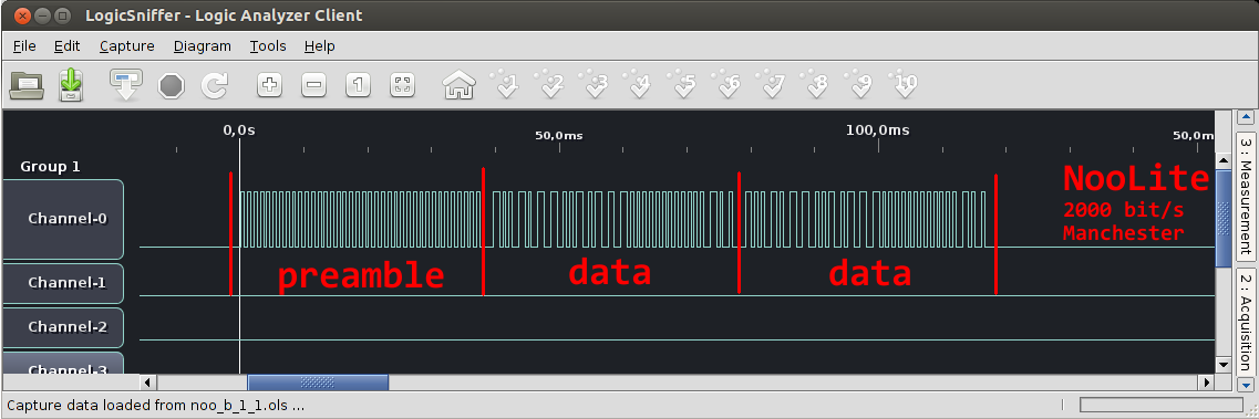
So, we sent the signal with the leg marked in red to the first channel of the logic analyzer, connected the ground and set the trigger in the analyzer client. Here's what happened:
In the picture, there is a dump of the package that the NooLite remote control sends over the radio when the button is pressed.
What can be said from such a picture? Actually quite a lot:
The minimum length of units and zeros is the same and is 500us. Data is transmitted at the physical level at a frequency of 2000 bit / s.
At the beginning of the transmission package, a large piece of a rectangular meander is visible. This is the so-called preamble, which helps the receiver to adjust the frequency of data transmission (bitrate) for a specific receiver. Both the receiver and the transmitter use the built-in RC oscillators to clock the microcontroller, so the “2000 baud” of the receiver and transmitter may differ by 10 percent.
After the pre-release, the data starts. The data follows a very recognizable pattern of Manchester coding : in the code there are only pairs of long zero-long unit and short zero-short unit. “Long” sections with a constant level are exactly two times longer than short ones, i.e. are two “physical” bits. The package does not contain sequences of zeros or ones longer than 2 bits.
Such a harater pattern is obtained if the source data is encoded as follows: transmit two bits, “01”, for each unit and “10” for each zero. What is Manchester code written in detail on Wikipedia, but if very briefly, then use it for two things: firstly, it allows you to get rid of the constant component of the signal, and secondly, it does not require the coincidence of the frequency of the receiver and transmitter, allowing you to restore the frequency from the received signal.
Another observation regarding data: in the packet, the same data block is transmitted twice. This is apparently done to reduce the chances of packet damage due to interference and interference (recall, in Noolite there is no confirmation of message delivery)

(two identical data packets, larger)
Digitize data
Unfortunately, the software for the logic analyzer has rather short possibilities for the analysis of arbitrary protocols. We never managed to get the Manchester coding decoder to work in it, so we will write our own.
First, export the data as csv. The file will record the time of each change in our signal.
They look something like this
The first column is time, the last column is the state of our channel.
"timestamp (abs)","timestamp (rel)","sample rate (Hz)","Channel-7","Channel-6","
Channel-5","Channel-4","Channel-3","Channel-2","Channel-1","Channel-0"
0,-2454,100000,0,0,0,0,0,0,0,0
2456,2,100000,0,0,0,0,0,0,0,1
2505,51,100000,0,0,0,0,0,0,0,0
2555,101,100000,0,0,0,0,0,0,0,1
2605,151,100000,0,0,0,0,0,0,0,0
2655,201,100000,0,0,0,0,0,0,0,1
2704,250,100000,0,0,0,0,0,0,0,0
2755,301,100000,0,0,0,0,0,0,0,1
2804,350,100000,0,0,0,0,0,0,0,0
2854,400,100000,0,0,0,0,0,0,0,1
2904,450,100000,0,0,0,0,0,0,0,0
2954,500,100000,0,0,0,0,0,0,0,1
3003,549,100000,0,0,0,0,0,0,0,0
3054,600,100000,0,0,0,0,0,0,0,1
3103,649,100000,0,0,0,0,0,0,0,0
3153,699,100000,0,0,0,0,0,0,0,1
3203,749,100000,0,0,0,0,0,0,0,0

(picture from Wikipedia)
The logic for decoding a Manchester code is very simple: you can see that the long gap between the edges encodes a data bit that differs from the previous one. If the next data bit does not differ from the previous one, then it will be encoded with two short gaps between the edges.
Relevant Python Code
#coding: utf-8
import csv
import sys, time
reader = csv.DictReader(open(sys.argv[1]))
#~ reader.next()
channel = 'Channel-0'
delays = []
freq = None
prev_ts = None
state = False
out_short = True
def print_packet(packet):
	checksum = False
	line = ''
	for bit in packet:
		line+= '1' if bit else '0'
		line+= ','
		checksum ^= bit
	#~ print line, "=", checksum
	print line
packet = []
packets = []
prev_val = None
for row in reader:
	freq = int(row['sample rate (Hz)'])
	ts = int(row['timestamp (abs)'])
	val = int(row[channel])
	#~ print row
	if val == prev_val:
		continue
	prev_val = val
	if prev_ts:
		delay = 1.0/freq * (ts-prev_ts)
		if delay > 1000E-6 * 1.3:
			#~ print "pause"
			state = False
			packets.append(packet)
			packet = []
			out_short = True
		elif delay > 500E-6 * 1.3:
			#~ print "long"
			state = not state
			packet.append(state)
			out_short = True
		else:
			#~ print "short"
			# short
			out_short = not out_short
			if out_short:
				packet.append(state)
	prev_ts = ts
#~ for packet in packets:
	#~ print_packet(packet)
print sys.argv[1],",",
#~ assert packets[0] == [0,]*37
#~ assert (packets[1] == packets[2])
#~ print packets
print_packet(packets[1])
print_packet(packets[2])
# 5 в начале меняются между программированием и норм. режимом и в кнопках
# на отпускание посылается одна и та же команда
Analysis
We press different buttons on different remotes, record what happens. In the process, we noticed that sending commands for dimming is done in an original way: when the button is pressed, the remote control sends one command (“start increasing brightness”), when released, it sends another one (“finish increasing brightness”).
We collect statistics in a plate:

Some hints are given by the documentation for the original Noolite modules for the computer.
First, we take command codes from the documentation and try to find them in the bit stream. The command code is detected in 4 bits, starting with the second. The code is written according to the LSB scheme , i.e. first significant digit back.
In addition to the command, two bytes of the address are easily allocated (they remain unchanged for any commands of one console) and a byte of the "argument" filled with zeros. When sending the same command again between the two possible values, the value of the first bit and the last 8 bits change.
All parcels have constant parity, i.e. xor of all bits gives the same value. This behavior hints at the presence of a checksum.
Check sum
The first idea was to use parity as the checksum, which is written to the first bit of the packet. The continued parity of the packet and the fact that the first bit is separate from the other bits in the packet spoke in favor of this version.
However, attempts to figure out the meaning of the last byte did not lead to anything good.
The next idea, which turned out to be true, was that the checksum is the last 8 bits. The first bit is used so that the receiver can distinguish two consecutive button presses from one (as we said, with one press the sending is repeated several times for reliability).
The first candidate for the checksum is of course CRC. However, the CRC-8 algorithm generally has three 8-bit parameters, and enumerating a pair of frequently used combinations did not lead to success.
We send commands
It was decided to try to generate Noolite packages and check their "validity" using the execution unit, which blinks when receiving a valid package.
To do this, we drew a simple sketch for the arduino, which was connected to the input of the analog part of the disassembled noolight console.
A sketch looks something like this
#define UINT8 unsigned char
// Pin 13 has an LED connected on most Arduino boards.
// give it a name:
int gpio = 12;
// the setup routine runs once when you press reset:
void setup() {
  // initialize the digital pin as an output.
  pinMode(gpio, OUTPUT);
  Serial.begin(115200);
}
const unsigned int PERIOD = 500; //usec
void send_sequence(int count, unsigned char * sequence) {
  char clock = 1;
  for (int i = 0; i < count; ++i) {
    char data = sequence[i];
    clock = !clock;
    digitalWrite(gpio, clock ^ (!data));
    delayMicroseconds(PERIOD);
    clock = !clock;
    digitalWrite(gpio, clock ^ (!data));
    delayMicroseconds(PERIOD);
  }
}
// Automatically generated CRC function
// polynomial: 0x131, bit reverse algorithm
UINT8
crc8_maxim(UINT8 *data, int len, UINT8 crc)
{
    static const UINT8 table[256] = {
    0x00U,0x5EU,0xBCU,0xE2U,0x61U,0x3FU,0xDDU,0x83U,
    0xC2U,0x9CU,0x7EU,0x20U,0xA3U,0xFDU,0x1FU,0x41U,
    0x9DU,0xC3U,0x21U,0x7FU,0xFCU,0xA2U,0x40U,0x1EU,
    0x5FU,0x01U,0xE3U,0xBDU,0x3EU,0x60U,0x82U,0xDCU,
    0x23U,0x7DU,0x9FU,0xC1U,0x42U,0x1CU,0xFEU,0xA0U,
    0xE1U,0xBFU,0x5DU,0x03U,0x80U,0xDEU,0x3CU,0x62U,
    0xBEU,0xE0U,0x02U,0x5CU,0xDFU,0x81U,0x63U,0x3DU,
    0x7CU,0x22U,0xC0U,0x9EU,0x1DU,0x43U,0xA1U,0xFFU,
    0x46U,0x18U,0xFAU,0xA4U,0x27U,0x79U,0x9BU,0xC5U,
    0x84U,0xDAU,0x38U,0x66U,0xE5U,0xBBU,0x59U,0x07U,
    0xDBU,0x85U,0x67U,0x39U,0xBAU,0xE4U,0x06U,0x58U,
    0x19U,0x47U,0xA5U,0xFBU,0x78U,0x26U,0xC4U,0x9AU,
    0x65U,0x3BU,0xD9U,0x87U,0x04U,0x5AU,0xB8U,0xE6U,
    0xA7U,0xF9U,0x1BU,0x45U,0xC6U,0x98U,0x7AU,0x24U,
    0xF8U,0xA6U,0x44U,0x1AU,0x99U,0xC7U,0x25U,0x7BU,
    0x3AU,0x64U,0x86U,0xD8U,0x5BU,0x05U,0xE7U,0xB9U,
    0x8CU,0xD2U,0x30U,0x6EU,0xEDU,0xB3U,0x51U,0x0FU,
    0x4EU,0x10U,0xF2U,0xACU,0x2FU,0x71U,0x93U,0xCDU,
    0x11U,0x4FU,0xADU,0xF3U,0x70U,0x2EU,0xCCU,0x92U,
    0xD3U,0x8DU,0x6FU,0x31U,0xB2U,0xECU,0x0EU,0x50U,
    0xAFU,0xF1U,0x13U,0x4DU,0xCEU,0x90U,0x72U,0x2CU,
    0x6DU,0x33U,0xD1U,0x8FU,0x0CU,0x52U,0xB0U,0xEEU,
    0x32U,0x6CU,0x8EU,0xD0U,0x53U,0x0DU,0xEFU,0xB1U,
    0xF0U,0xAEU,0x4CU,0x12U,0x91U,0xCFU,0x2DU,0x73U,
    0xCAU,0x94U,0x76U,0x28U,0xABU,0xF5U,0x17U,0x49U,
    0x08U,0x56U,0xB4U,0xEAU,0x69U,0x37U,0xD5U,0x8BU,
    0x57U,0x09U,0xEBU,0xB5U,0x36U,0x68U,0x8AU,0xD4U,
    0x95U,0xCBU,0x29U,0x77U,0xF4U,0xAAU,0x48U,0x16U,
    0xE9U,0xB7U,0x55U,0x0BU,0x88U,0xD6U,0x34U,0x6AU,
    0x2BU,0x75U,0x97U,0xC9U,0x4AU,0x14U,0xF6U,0xA8U,
    0x74U,0x2AU,0xC8U,0x96U,0x15U,0x4BU,0xA9U,0xF7U,
    0xB6U,0xE8U,0x0AU,0x54U,0xD7U,0x89U,0x6BU,0x35U,
    };
    while (len > 0)
    {
        crc = table[*data ^ (UINT8)crc];
        data++;
        len--;
    }
    return crc;
}
void convert_to_buf(unsigned char val, unsigned char* buf) {
  unsigned char  mask = 1;
  for (int i = 0; i  < 8; ++ i) {
    if (val & mask) {
      buf[i] = 1;
    } else {
      buf[i] = 0;
    }
    mask = mask << 1;
  }
}
unsigned char calc_checksum(int count, unsigned char * sequence) {
  unsigned char data[] = {0,0,0,0};
  unsigned char mask  ;
  // first byte from 1 to 5 bit (0-based)
  for (int i=1; i < 6; ++i) {
    if (sequence[i]) {
      //bit 1 to  2**3 mask
      mask = 1 << (i + 2);
      data[0] |= mask;
    }
  }
  for (int byte_n=0; byte_n < 3; ++byte_n) {
    // [] = 6 + byte_n * 8 + i
    for (int i=0; i < 8; ++i) {
      if (sequence[6 + byte_n * 8 + i]) {
        mask = 1 << i;
        data[byte_n + 1] |= mask;
     }
    }
  }
  return crc8_maxim(data, 4, 0);
}
  unsigned char preamble[] = {1,1,1,1,1,1,1,1,
                     1,1,1,1,1,1,1,1,
                     1,1,1,1,1,1,1,1,
                     1,1,1,1,1,1,1,1,
                     1,1,1,1,1,1};
  unsigned char command[] = {1,
                   0,
                   1,0,0,1,
                   1,0,0,1,0,1,1,0,
                   0,0,1,0,0,0,0,1,
                   /*1,1,1,1,1,0,0,0,
                   0,0,0,0,0,0,0,0,*/
                   0,0,0,0,0,0,0,0,
  };
// the loop routine runs over and over again forever:
void loop() {
  unsigned char checksum[] = {0,0,0,0,0,0,0,0};
  for (unsigned int addr_lo = 0; addr_lo < 256; ++addr_lo) {
    for (unsigned int addr_hi = 0; addr_hi < 256; ++addr_hi) {
      Serial.println(addr_hi);
      Serial.println(addr_lo);
      convert_to_buf(addr_hi, command + 6);
      convert_to_buf(addr_lo, command + 6 + 8);
      unsigned char checksum_val = calc_checksum(sizeof(command), command);
          convert_to_buf(checksum_val, checksum);
          // Serial.println(checksum_val);
        //  if (checksum_val==198) continue;
          delay(10);
          send_sequence(sizeof(preamble), preamble);
          digitalWrite(gpio, LOW);
          delayMicroseconds(500 * 3);
          send_sequence(sizeof(command), command);
          send_sequence(sizeof(checksum), checksum);
          digitalWrite(gpio, LOW);
          delayMicroseconds(500 * 3);
          send_sequence(sizeof(command), command);
          send_sequence(sizeof(checksum), checksum);
          digitalWrite(gpio, LOW);
          delayMicroseconds(500 * 3);
          digitalWrite(gpio, LOW);
      }
    }
  //    command[1] = !command[1];
    //  Serial.println(command[1]);
    //  delay(4000);
  while (1) {};
}
Here, we simply give out onions and zeros using digitalWrite (). The duration of the pulses is adjustable delay.
After we checked that we can play one of the recorded packages, and the noolight block takes it for ours, we started further experiments.
Checksum 2
As it was written above, it was necessary to understand the checksum generation algorithm.
The CRC algorithm has a good property that can be checked: this checksum is linear in the arguments.

Thus, if you take two well-known packages, add them bitwise (i.e. make xor), then the resulting package will have the correct checksum!
Having chosen two suitable packages, we check this assumption and confirm that the check sum is linear in the arguments.
Checksum 3
Our next action was brute force checksums. Using a binary search for a given sequence of bits, the checksum is selected in a few minutes. This is done in an obvious way: we run a sketch that goes through checksums from 1 to 128 and look at the receiver. If during the operation of the sketch he blinked (received a valid package), then we know that the desired checksum is somewhere from 1 to 128. And so on.
Now that we can determine the checksums of an arbitrary package, we can try to restore the function. Because CRC is linear in arguments, then, knowing how the cx-sum changes with each bit, you can restore the function.
To restore the function, you need to select the checksums to the number of packets equal to the number of bits in the packet, i.e. to 29 packages.

This is done all slowly and managed to get tired of the order. So, having passed more than half of the bits, we decided to quickly try to sort out the checksums offline.
Checksum 4
As described above, CRC has several input parameters: polynomial (8-bit), initial value (8-bit), value that is added at the end (8-bit). In addition, 1 bit - sets whether the algorithm is inverted or not.
In addition to these parameters, it is possible to prepare bytes in different ways with which the CRC algorithm operates. There are 29 bits in the noolite package, i.e. non-integer bytes. The question is how to form the first byte. In addition, each byte can be flipped when calculating CRC. Moreover, theoretically, not only bits in a byte, but also bytes in pairs (words) can be flipped.
We will sort it all out with brute force. For brute force, we used Python and the crcmod library .
sample code
import crcmod
samples = [
 #~ ['\x00\x00\x01' + chr(0b11110000),  chr(0b11011010)],
 #~ ['\x00\x00\x03' + chr(0b11110000),  chr(0b10010101)],
 [chr(0b11110000) + '\x01\x00\x00',  chr(0b11011010)],
 [chr(0b11110000) + '\x03\x00\x00',  chr(0b10010101)],
 [chr(0b11110000) + chr(0b1) + chr(0b1) + '\x00',  chr(0b00011110)],
 [chr(0b11111000) + chr(0b1) + chr(0b1) + '\x00',  chr(0b00000010)],
 #~ [chr(0b11111000) + chr(0b1) + chr(0b1) + '\x00',  chr(0b00000010)],
]
#~ predef = crcmod.predefined.mkPredefinedCrcFun('crc-8-maxim')
predef = crcmod.Crc(256 + 0x31,initCrc=0x00,rev=True)
for data, checksum in samples:
	print "="*10
	for poly in xrange(255):
		for init_crc in (0, 0xff):
			for rev in (True, False):
				digest = crcmod.Crc(256 + poly,initCrc=init_crc,rev=rev).new(data).digest()
				if digest == checksum:
					print poly, init_crc, rev
for data, checksum in samples:
	print "expected: ", hex(ord(checksum))
	print predef.new(data).hexdigest()
import sys
print predef.generateCode("crc8_maxim", sys.stdout)
Function found! This is the “crc8_maxim" scheme, the first 5 bits are first zeros left. Then all bytes are written to LSB, i.e. turn over.
Python Algorithm Code
crc8_table = [
    0x00,0x5E,0xBC,0xE2,0x61,0x3F,0xDD,0x83,
    0xC2,0x9C,0x7E,0x20,0xA3,0xFD,0x1F,0x41,
    0x9D,0xC3,0x21,0x7F,0xFC,0xA2,0x40,0x1E,
    0x5F,0x01,0xE3,0xBD,0x3E,0x60,0x82,0xDC,
    0x23,0x7D,0x9F,0xC1,0x42,0x1C,0xFE,0xA0,
    0xE1,0xBF,0x5D,0x03,0x80,0xDE,0x3C,0x62,
    0xBE,0xE0,0x02,0x5C,0xDF,0x81,0x63,0x3D,
    0x7C,0x22,0xC0,0x9E,0x1D,0x43,0xA1,0xFF,
    0x46,0x18,0xFA,0xA4,0x27,0x79,0x9B,0xC5,
    0x84,0xDA,0x38,0x66,0xE5,0xBB,0x59,0x07,
    0xDB,0x85,0x67,0x39,0xBA,0xE4,0x06,0x58,
    0x19,0x47,0xA5,0xFB,0x78,0x26,0xC4,0x9A,
    0x65,0x3B,0xD9,0x87,0x04,0x5A,0xB8,0xE6,
    0xA7,0xF9,0x1B,0x45,0xC6,0x98,0x7A,0x24,
    0xF8,0xA6,0x44,0x1A,0x99,0xC7,0x25,0x7B,
    0x3A,0x64,0x86,0xD8,0x5B,0x05,0xE7,0xB9,
    0x8C,0xD2,0x30,0x6E,0xED,0xB3,0x51,0x0F,
    0x4E,0x10,0xF2,0xAC,0x2F,0x71,0x93,0xCD,
    0x11,0x4F,0xAD,0xF3,0x70,0x2E,0xCC,0x92,
    0xD3,0x8D,0x6F,0x31,0xB2,0xEC,0x0E,0x50,
    0xAF,0xF1,0x13,0x4D,0xCE,0x90,0x72,0x2C,
    0x6D,0x33,0xD1,0x8F,0x0C,0x52,0xB0,0xEE,
    0x32,0x6C,0x8E,0xD0,0x53,0x0D,0xEF,0xB1,
    0xF0,0xAE,0x4C,0x12,0x91,0xCF,0x2D,0x73,
    0xCA,0x94,0x76,0x28,0xAB,0xF5,0x17,0x49,
    0x08,0x56,0xB4,0xEA,0x69,0x37,0xD5,0x8B,
    0x57,0x09,0xEB,0xB5,0x36,0x68,0x8A,0xD4,
    0x95,0xCB,0x29,0x77,0xF4,0xAA,0x48,0x16,
    0xE9,0xB7,0x55,0x0B,0x88,0xD6,0x34,0x6A,
    0x2B,0x75,0x97,0xC9,0x4A,0x14,0xF6,0xA8,
    0x74,0x2A,0xC8,0x96,0x15,0x4B,0xA9,0xF7,
    0xB6,0xE8,0x0A,0x54,0xD7,0x89,0x6B,0x35,
    ]
def crc8_maxim(data):
    crc = 0
    for i, ch in enumerate(data):
        crc = crc8_table[ord(ch) ^ crc]
    return crc
Subtotal
Now we know almost everything about the protocol and can generate arbitrary commands to turn on, turn off, start brightness adjustment and end brightness adjustment with arbitrary address values, emulating arbitrary Noolite remotes.
This, however, is not entirely enough. The fact is that among these commands there is no command such as "set the brightness to level X", which is very inconvenient when used with a smart home system. Controlling the brightness with the delay between the two commands, as is done with conventional Noolite remotes, is rather strange.
At the same time, the documentation for the NooLite modules for the computer shows that such commands exist. For example, the documentation for the command with code 6 says "value = 6 - set the brightness specified in “Data Byte 0”, set the brightness specified in Data Byte 0, 1, 2. ”
The penultimate byte in the packet, which was always zero in our experiments, was a natural candidate for“ Data Byte 0 ”. However , attempts to send a command in which this byte is non-zero were unsuccessful. Apparently, the sending format when sending commands with arguments is different.
Advanced teams
To deal with commands with arguments and put an end to the analysis of the Noolite protocol, you need native NooLite modules.
(Here, I would immediately like to thank the thinking-home.ru store and the habrovchanin dima117 for the promptly provided for this device)
If you have a native module, you can send commands, for example, using this program .
In addition to the command for setting the specified brightness, there are also commands that control the brightness and color switching mode of NooLite RGB blocks, as well as setting the color value (RGB).
This time, we will intercept commands using the RFM69H packet radio, which is installed in Wiren Board Smart Home using ourprotocol parsing code .
What happened:

It can be seen that the last byte, which was zero in our experiments, is actually the choice of format. We observed fmt = 0, besides this, values 1, 3 and 4 are possible.
Format 1 is used for the brightness setting command, and at the beginning of the packet one byte with the brightness value is added.
Format 3 is used for the command to set the color, 4 bytes are added to the beginning of the packet. The first three specify the color components, the fourth is always zero, its meaning is not clear (apparently reserved).
Format 4 is used for mode switching commands. For this reason, for some reason, 4 bits of the argument are added to the beginning of the package after the command. The entire packet is shifted to calculate the checksum, i.e. bytes are counted from the left, the remaining bits are padded with zeros to the byte.
Total
In total, we fully understood how the Noolite protocol works. What can be said about the protocol:
- The preamble and Manchester coding are used, this is good practice.
- Only 16 bits of the address are used. This is of course better than 4-8 bits in very cheap Chinese radio sets, but still quite a bit. For example, the new Chinese microchips for radio controllers have a code length of 21 bits. 16 bits are only 65,536 possible combinations, which allows you to sort through them quite quickly. If you have a powerful transmitter and a good antenna, you can, for example, start sending a command to turn off the lights in a cycle with all possible addresses. Such a thing will sort through all the addresses in a couple of hours and is guaranteed to turn off the lights from all your neighbors. And since the connection is one-way, the number of neighbors with whom you can turn off the light is limited only by the power of your transmitter.
- Redundancy in the protocol is realized by re-sending the packet and monitoring its integrity. Having integrity control is an absolute advantage of the protocol. On the other hand, redundant coding could be implemented in a more compact way, although in the case of transmission of short packets over the radio this may not be an advantage
- The protocol is completely lacking any protection. In this case, it would be possible to use a code such as KeeLoq - this is a code that, roughly speaking, is based on the synchronization of counters in the transmitter and receiver, is used in car key fobs. You can implement something similar even on the hardware that is now used in NooLite
- A rather strange package structure is used. The choice of format (i.e., including the length of the package ) is encoded with the last byte of the packet. Thus, packet separation is necessary at the physical level. More logical (and often used) is encoding the packet length at the very beginning of this packet. It is also not very clear why the packet was not trimmed to the byte boundary. A rather strange saving on three bits, given that as much as 8 bits are allocated for the format code.
Although this is not related to the protocol itself, the results of opening pocket-sized radio remote controls seemed interesting to us:
autopsy revealed
Actually the radio
remote control (pictures from the article ):

It’s disassembled:

But the board on the other hand: The

board is not only in the traditional Chinese version (that is, flux-caked), so it also says “livolo.com”.
Needless to say, remotes from livolo look identical ? At the same time they cost less than $ 5 .
Apparently, the fellow developers of NooLite buy ready-made livolo remotes and reflash them with their firmware, since the remote is made on PIC16, and the connector for programming it is conveniently displayed on the board. I must say, a very smart solution!
It’s disassembled:
But the board on the other hand: The
board is not only in the traditional Chinese version (that is, flux-caked), so it also says “livolo.com”.
Needless to say, remotes from livolo look identical ? At the same time they cost less than $ 5 .
Apparently, the fellow developers of NooLite buy ready-made livolo remotes and reflash them with their firmware, since the remote is made on PIC16, and the connector for programming it is conveniently displayed on the board. I must say, a very smart solution!
PS
NooLite manufacturers are going to release the MT1132 module with a UART interface, which is designed for use with Arduino, etc. or in your own devices.
We heard rumors that it would cost a little more adequately than native USB-sticks .
Naked advertising
Actually, you probably already understood the NooLite protocol, we sorted it out to add its support to Wiren Board Smart Home , our home automation controller with Linux on board and great peripheral connectivity, which, in particular, has a universal 433MHz transceiver.
We send the order for the first batch to the plant this Wednesday, so we decided to extend the pre-order for three days until Tuesday, March 18, inclusive . You can buy a controller (shipping in late April - early May) in our store .
Only registered users can participate in the survey. Please come in.
What else would we disassemble and support?
- 69.3% Livolo 104 Circuit Breakers
- 54% Wireless X10 81
- 5.3% (suggest in the comments) 8