Putting a pocket laser
In this post, I will describe how I collected a purple laser pointer from the rubbish found at hand. To do this, I needed: a purple laser diode, a collimator for converging the light beam, driver details, a laser housing, a power supply, a good soldering iron, straight arms, and a desire to create.
Those interested and wanting to dig deeper into electronics - please, under cat.
I got my arm killed Blu-ray cutter. It was a pity to throw it away, but what I could make of it - I did not know. Six months later, I came across a video in which such a home-made "toy" was shown. Then the blues came in handy!
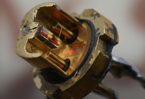
The drive's read / write system uses a laser diode. It looks in most cases like this:
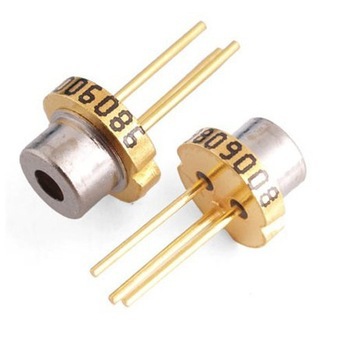
Or like that.
To supply a “red” diode, 3-3.05 volts are needed, and from 10-15 to 1500-2500 milliamps, depending on its power.
But the diode “violet” requires as much as 4.5-4.9 volts, so it will not work to feed through a resistor from a lithium battery. Have to make a driver.
Since I had a positive experience with the ZXSC400 chip, I chose it without hesitation. This chip is a driver for high-power LEDs. Datashit. With a strapping in the form of a transistor, a diode and an inductance, I did not become wiser - everything is from a datasheet.
I made a printed circuit board for the laser driver for the well-known to many amateur radio enthusiasts LUT-ohm (Laser-iron technology). This requires a laser printer. The diagram is drawn in the SprintLayout5 program and printed on film for further transfer of the picture to textolite. Almost any film can be used, if only it wouldn’t get stuck in the printer and print on it qualitatively. The film from plastic envelope folders is quite suitable.
If there is no film, no need to get upset! We borrow a female glossy magazine from a friend or wife, cut out the most uninteresting page from there, and customize it to A4 size. Then print.
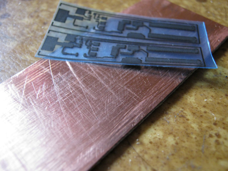
In the photo below, you can see a film with applied toner in the form of a wiring diagram, and a piece of PCB prepared for toner transfer. The next step will be the preparation of the PCB. It is best to take a piece, two times larger than our scheme, so that it is more convenient to press it to the surface during the next step. The copper surface must be sanded and degreased.
Now you need to transfer the "drawing". We find the iron in the cabinet, turn it on. While it is warming up, put a piece of paper with a diagram on the textolite.
As soon as the iron heats up, you need to gently smooth the film through the paper.
This video shows the process very clearly.
When it “sticks” to the PCB, you can turn off the iron and go to the next step.
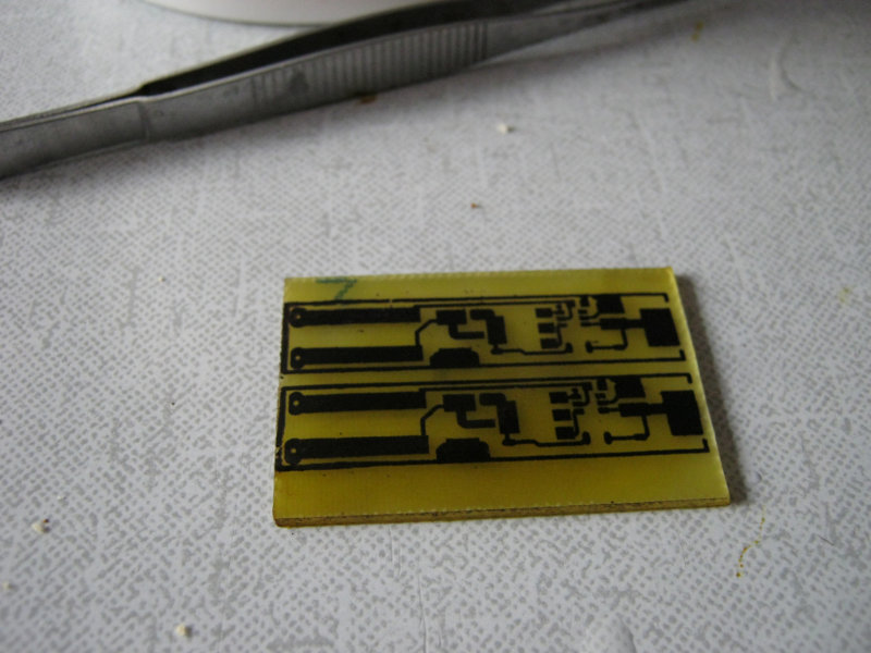
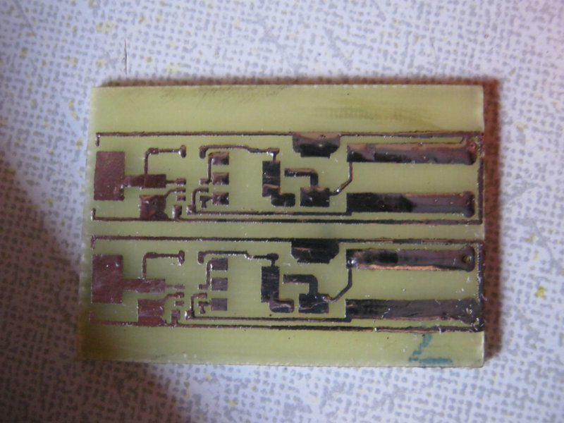
After transferring the toner with a conventional iron, this is how it looks:
If some of the tracks did not transfer, or if they did not transfer very well, they can be corrected with a CD marker and a sharp needle. It is advisable to use a magnifying glass, the tracks are quite small, only 0.4 mm. The board is ready for pickling.
We will poison with ferric chloride. 150 rubles per jar, enough for a long time.
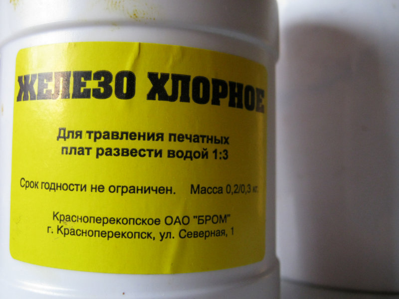
We dilute the solution, throw our billet there, “stir” the board and wait for the result.
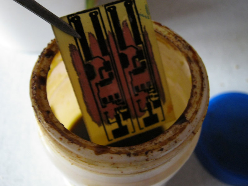
Do not forget to control the process. Carefully pull out the board with tweezers (it is also better to buy it, this will save us from excess mat and “snot” solder on the future board when soldering).
Well, the board has been corrupted!
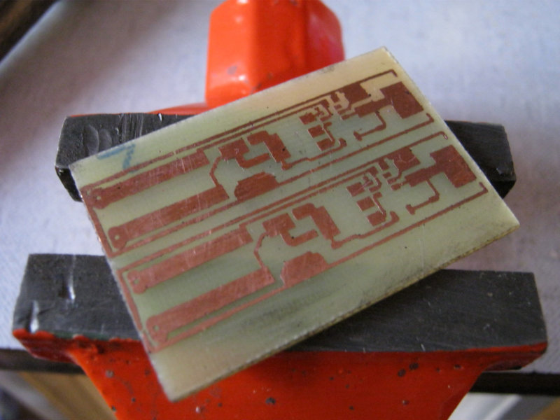
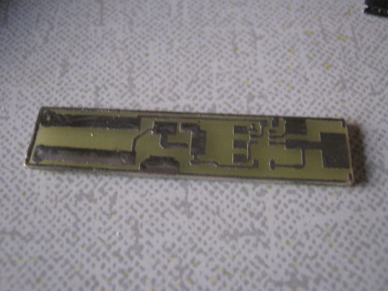
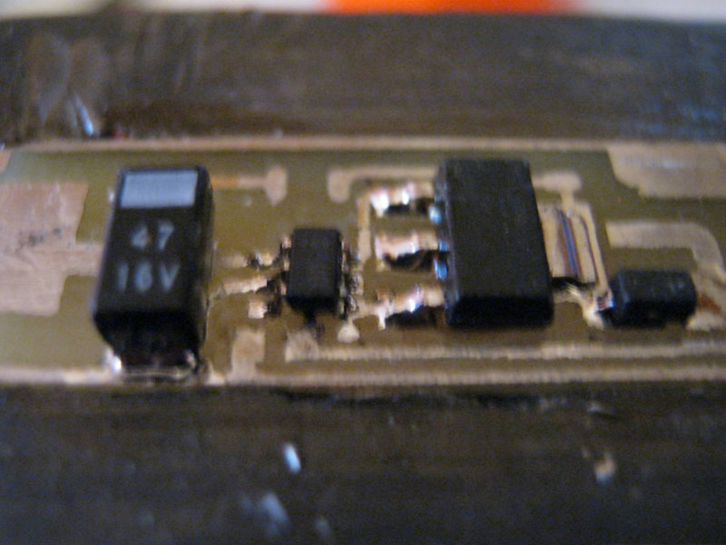
Carefully clean with a fine skin, apply flux, tin. This is what happens after tinning.
It is possible to apply a little more solder pads than anywhere else to solder parts more conveniently, and without applying solder additionally.
It remains to cut a little further outlined contours, and grind excess files. I made the driver in duplicate - just in case. It is convenient to cut textolite with scissors for metal.
We will assemble the driver according to this scheme. Note: R1 is 18 milliohms , not megohms !
When soldering, it is best to use a soldering iron with a thin tip, for convenience you can use a magnifying glass, because the details are quite small. This soldering uses the LTI-120 flux.
So, the board is almost soldered.
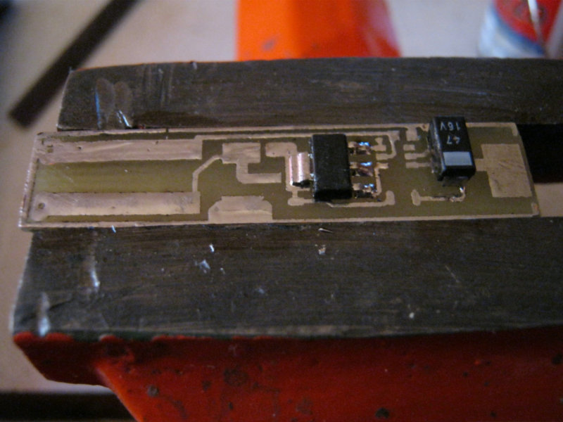

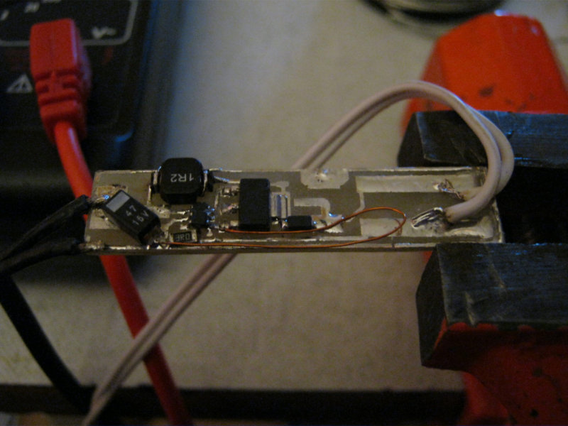
The wire is soldered to the place of the resistor at 0.028 Ohms, since we are unlikely to find such a resistor. You can solder in parallel 3-4 SMD jumpers (look like resistors, but with the inscription 0), they have about 0.1 ohms of real resistance.
But there were none of these, so I used an ordinary copper wire of similar resistance. I didn’t measure it exactly - just the calculations of some online calculator.
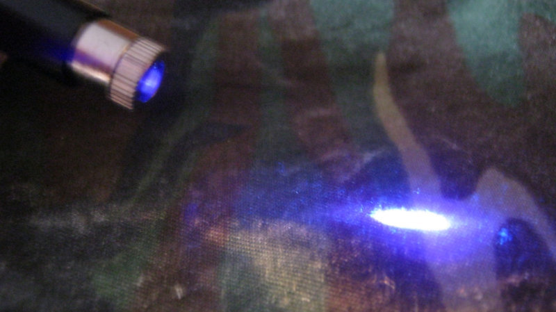
We are testing.
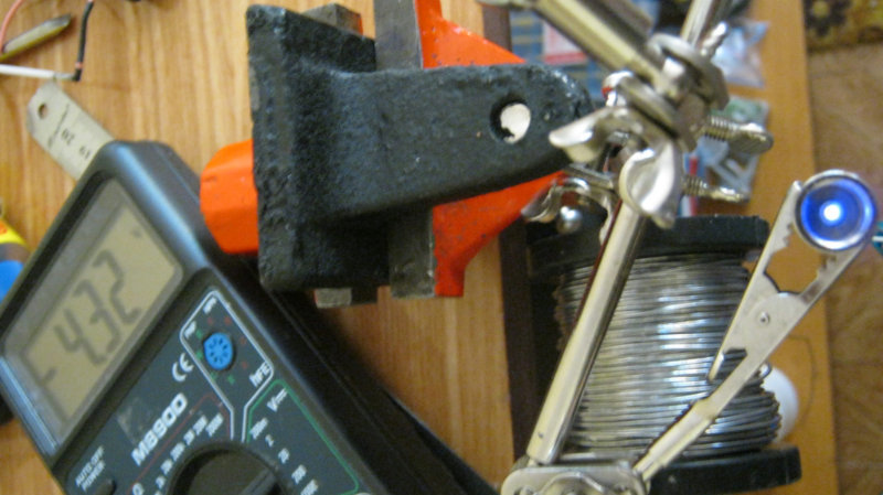
The voltage is set to only 4.5 volts, so it does not shine very brightly.
Of course, the board looks dirty before flushing the flux. You can rinse with simple alcohol.
Now it’s worth writing about the collimator. The fact is that the laser diode itself does not shine with a thin beam. If you turn it on without optics, it will shine like a regular LED with a divergence of 50-70 degrees. In order to create a beam, you need optics and the collimator itself.
The collimator is ordered from China . It also contains a weak red diode, but I did not need it. The old diode can be knocked out with an ordinary M6 bolt.
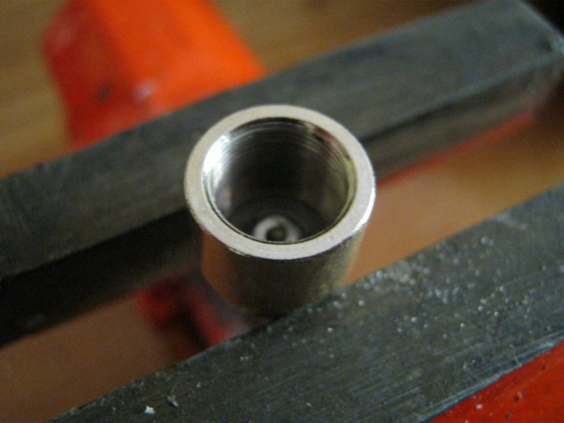
We unwind the collimator, unscrew the lens and the back, and unsolder the driver from the diode. The remaining mount is clamped in a vice. You can knock out a diode by hitting it.
The diode is knocked out.
Now you need to press in a new purple diode.
But you can’t press the diode on its legs, but it is inconvenient to press in another way.
What to do?
The back of the collimator is great for this.
We insert a new diode with legs into the hole in the rear of the cylinder, and clamp it in a vice.
Gently twist the vice until the diode is completely pressed into the collimator.
So, the driver and collimator are assembled.
Now we fix the collimator in the "head" of our laser, and solder the diode to the driver outputs using wiring, or directly to the driver board.
As a case, I decided to use a simple flashlight from a hardware store for a hundred rubles.
It looks like this:
All the glands for the laser and the collimator.
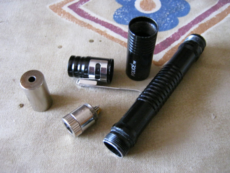
A magnet is fastened to the clothespin for convenience of fastening.
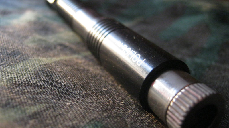
It remains only to insert the laser device into the housing and tighten.
Sprint layout 5, archived PCB layout files .
PS This pocket laser is a rather dangerous "toy." Class I-II lasers are not particularly dangerous for humans and eyes, unless the diode accidentally enters the eye if assembly is unsuccessful. But classes III-IV can damage or deprive vision at all. It is necessary to use glasses . It is impossible to direct the beam towards people, and even more so in the face .
The Chinese red pointer shines with a power of 0.5-1 mW. This laser has a power of 150-200 milliwatts. Imagine that 150-200 pointers were sent to you at the same time!
Those interested and wanting to dig deeper into electronics - please, under cat.
I got my arm killed Blu-ray cutter. It was a pity to throw it away, but what I could make of it - I did not know. Six months later, I came across a video in which such a home-made "toy" was shown. Then the blues came in handy!
The drive's read / write system uses a laser diode. It looks in most cases like this:
Or like that.
To supply a “red” diode, 3-3.05 volts are needed, and from 10-15 to 1500-2500 milliamps, depending on its power.
But the diode “violet” requires as much as 4.5-4.9 volts, so it will not work to feed through a resistor from a lithium battery. Have to make a driver.
Since I had a positive experience with the ZXSC400 chip, I chose it without hesitation. This chip is a driver for high-power LEDs. Datashit. With a strapping in the form of a transistor, a diode and an inductance, I did not become wiser - everything is from a datasheet.
I made a printed circuit board for the laser driver for the well-known to many amateur radio enthusiasts LUT-ohm (Laser-iron technology). This requires a laser printer. The diagram is drawn in the SprintLayout5 program and printed on film for further transfer of the picture to textolite. Almost any film can be used, if only it wouldn’t get stuck in the printer and print on it qualitatively. The film from plastic envelope folders is quite suitable.
If there is no film, no need to get upset! We borrow a female glossy magazine from a friend or wife, cut out the most uninteresting page from there, and customize it to A4 size. Then print.
In the photo below, you can see a film with applied toner in the form of a wiring diagram, and a piece of PCB prepared for toner transfer. The next step will be the preparation of the PCB. It is best to take a piece, two times larger than our scheme, so that it is more convenient to press it to the surface during the next step. The copper surface must be sanded and degreased.
Now you need to transfer the "drawing". We find the iron in the cabinet, turn it on. While it is warming up, put a piece of paper with a diagram on the textolite.
As soon as the iron heats up, you need to gently smooth the film through the paper.
This video shows the process very clearly.
When it “sticks” to the PCB, you can turn off the iron and go to the next step.
After transferring the toner with a conventional iron, this is how it looks:
If some of the tracks did not transfer, or if they did not transfer very well, they can be corrected with a CD marker and a sharp needle. It is advisable to use a magnifying glass, the tracks are quite small, only 0.4 mm. The board is ready for pickling.
We will poison with ferric chloride. 150 rubles per jar, enough for a long time.
We dilute the solution, throw our billet there, “stir” the board and wait for the result.
Do not forget to control the process. Carefully pull out the board with tweezers (it is also better to buy it, this will save us from excess mat and “snot” solder on the future board when soldering).
Well, the board has been corrupted!
Carefully clean with a fine skin, apply flux, tin. This is what happens after tinning.
It is possible to apply a little more solder pads than anywhere else to solder parts more conveniently, and without applying solder additionally.
It remains to cut a little further outlined contours, and grind excess files. I made the driver in duplicate - just in case. It is convenient to cut textolite with scissors for metal.
We will assemble the driver according to this scheme. Note: R1 is 18 milliohms , not megohms !
When soldering, it is best to use a soldering iron with a thin tip, for convenience you can use a magnifying glass, because the details are quite small. This soldering uses the LTI-120 flux.
So, the board is almost soldered.
The wire is soldered to the place of the resistor at 0.028 Ohms, since we are unlikely to find such a resistor. You can solder in parallel 3-4 SMD jumpers (look like resistors, but with the inscription 0), they have about 0.1 ohms of real resistance.
But there were none of these, so I used an ordinary copper wire of similar resistance. I didn’t measure it exactly - just the calculations of some online calculator.
We are testing.
The voltage is set to only 4.5 volts, so it does not shine very brightly.
Of course, the board looks dirty before flushing the flux. You can rinse with simple alcohol.
Now it’s worth writing about the collimator. The fact is that the laser diode itself does not shine with a thin beam. If you turn it on without optics, it will shine like a regular LED with a divergence of 50-70 degrees. In order to create a beam, you need optics and the collimator itself.
The collimator is ordered from China . It also contains a weak red diode, but I did not need it. The old diode can be knocked out with an ordinary M6 bolt.
We unwind the collimator, unscrew the lens and the back, and unsolder the driver from the diode. The remaining mount is clamped in a vice. You can knock out a diode by hitting it.
The diode is knocked out.
Now you need to press in a new purple diode.
But you can’t press the diode on its legs, but it is inconvenient to press in another way.
What to do?
The back of the collimator is great for this.
We insert a new diode with legs into the hole in the rear of the cylinder, and clamp it in a vice.
Gently twist the vice until the diode is completely pressed into the collimator.
So, the driver and collimator are assembled.
Now we fix the collimator in the "head" of our laser, and solder the diode to the driver outputs using wiring, or directly to the driver board.
As a case, I decided to use a simple flashlight from a hardware store for a hundred rubles.
It looks like this:
All the glands for the laser and the collimator.
A magnet is fastened to the clothespin for convenience of fastening.
It remains only to insert the laser device into the housing and tighten.
Sprint layout 5, archived PCB layout files .
PS This pocket laser is a rather dangerous "toy." Class I-II lasers are not particularly dangerous for humans and eyes, unless the diode accidentally enters the eye if assembly is unsuccessful. But classes III-IV can damage or deprive vision at all. It is necessary to use glasses . It is impossible to direct the beam towards people, and even more so in the face .
The Chinese red pointer shines with a power of 0.5-1 mW. This laser has a power of 150-200 milliwatts. Imagine that 150-200 pointers were sent to you at the same time!