Full-featured SDHC memory card driver for Stm32f4 (part 1)
What is this article for?
All embedders, sooner or later, face the problem of lack of ROM microcontroller for their projects. Well, corny, you need to develop a control system for a simple CNC machine, where the control program is stored on the device itself or a data collection system, say, from sensors of some experiment - it is obvious that the microcontroller was not originally designed to store such arrays of information.
There are a lot of solutions for this case, from the purchase and connection of EEPROM chips to the connection of a standard USB flash drive to the hardware USB host of the stone (if there is one, of course). Well, for hand-made projects, the best option is the most classic SD memory card. They come in different types, have different mechanisms for initializing and transmitting data, and are connected to the host via various interfaces (there are, however, only three of them, but more on that later). Moreover, many modern microcontrollers have on-board hardware modules of these interfaces, and the developer’s work comes down only to configuring them and sending the necessary commands to the card in accordance with the protocol. Well, even memory cards have a pleasant property of simply buying at every step.
About Secure Digital (SD) Cards
I will not rewrite Wikipedia - I will give here the basic information and types of SD memory cards and their characteristics.
Secure Digital format - a popular (perhaps the most popular today) flash memory format for use mainly in portable devices. Inside each such card there is, in fact, a flash memory chip (Memory Core) and a controller connecting it with the outside world that has 8 registers. The tasks of the latter are the hardware implementation of external interfaces, support for information about the card (type, capacity, speed class is still a bunch of other characteristics), power control, and, of course, management of the micro memory itself (addressing, reading, writing, cleaning and organizing about 80 control commands )
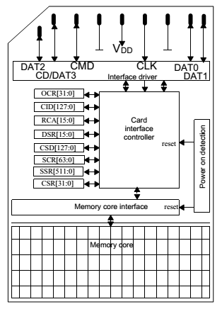
SD format was founded by Panasonic, SanDisk and Toshiba based on MMC cards. These companies later created the SD Card Association, which is currently developing and promoting SD technology. The main document that thoroughly describes the interface, protocol, commands, card registers is the Physical Layer Simplified Specification (Copyright 2001-2006 SD Group (Panasonic, SanDisk, Toshiba) and SD Card Association). This information is used by all sorts of R&D centers when developing hardware and software for their future devices. The file itself safely lies in the public domain in the internet, and there are no difficulties in downloading it. So, in accordance with this document, the following types of memory cards exist:
• SDcards (or SDSC (Secure Digital Standard Capacity)) - the first generation of memory cards. The volume limit is 2 GB. The minimum addressable space is 1 byte.
• SDHCCards (Secure Digital High Capacity) - high-capacity memory cards (up to 32 GB). They have a significant difference from the first type, namely, addressing occurs in blocks of 512 bytes and no one in this world can change this value. In other words, one cannot just take and write, for example, 71 bytes of information: the minimum packet size, again, 512 bytes. I didn’t particularly dig up why this is so, but there is a personal opinion that this is due to the 32-bit address space of the controller and because memory cards are usually formatted for one or another file system, the cluster size of which is conveniently combined with such blocks . SDHC cards also have an initialization process, which we will talk about a bit later.
• SDXC(Secure Digital eXtended Capacity) - memory cards with extended capacity - theoretically up to 2TB of memory. Addressing is also 512 bytes. So it turns out with 32-bit space: (2 ^ 32) * 512 = 2 Tb.
There are specifications for each generation of cards, and at the same time, information about old ones is described in each document for a newer generation - that is, they "get fat" with each product update. So download the Physical Layer Simplified Specification of the latest version and find there everything you need to work with all generations of cards. In addition, memory cards are divided into several classes according to the speed of reading / writing data. Well, as for all kinds of mini-, microSD, microSDXC, etc. - this is just another case size and pinout - no internal differences from standard size cards.
And now it’s important:Regardless of the type of card, capacity, its manufacturer, type of case, color and store where you bought it, all Security Digital cards have the same interaction interfaces with the outside world. Commands, initialization mechanisms are different, yes, but the interfaces are the same. This is what allows you to plug into the camera both SD and SDHC memory cards. Well, now the moment has come to discuss the language of the card, or rather, as many as three: SD and UHS-II (active speaker) and "the language of universal microprocessor communication, which every
Memory card interface
As mentioned above, Security Digital cards have three external interfaces: SD, UHS-II and SPI. The former are the “native” channels for exchanging data with the host, and, as a result, allow for the implementation of full-featured, full-speed interaction. SPI does not support a number of commands and does not provide maximum data exchange speed, but it is in all microcontrollers (both in modern and old models), which makes it possible to connect the card to everything that is bad without any problems. There are lots of articles on how to do this. But, with the development of microprocessor technology, with the reduction of nanometers in the technological process of stone production, the SPI interface, as a means of communication with an SD card, is gradually dying. Indeed, if your MK supports the hardware implementation of the SD protocol, Will you mess with a less functional alternative? Fate sent me to the project a stone Stm32f4 from STMicroelectronics, which just does have a peripheral module SDIO (Security Digital Input Output), which hardware implements both the interface and the protocol of the card.
So what is the SD protocol and what does it eat with? There are three key concepts here:
• command - a sequence of bits perceived by the card controller and calling it to one or another action;
• response - the response of the card controller to the command. It can contain both general information (card status, current status of various internal modules, etc.), and, in fact, information expected by the host (they requested a card identifier in a command - they received it in a response);
• data - well, there are no comments.
But before we look at the logic of the protocol, we turn to the physics of the interface (very overview).
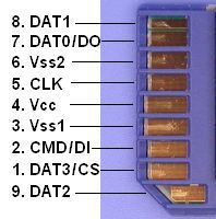
Pin 4 - power card;
Pin 3, 6 - ground;
Pin 5 - a clock signal;
Pin 2 - a line of commands and responses;
Pin 1, 7, 8, 9 - lines of a 4-bit data bus.
All sendings to and from the card are bit sequences that are strictly synchronized with the clock signal transmitted via the CLK line . Recommended frequencies are described in the specification for the card and have different meanings, depending on its type and speed class. I only note that for any card, initialization takes place at a very low (compared to data transfer) frequency. The data bus can be 1-bit (only D0 works) or 4-bit - this is configured during initialization. It is important that for SD cards on the host side, the data and command lines must be Push-Pull andbe pulled up to power via 4.5-10 kOhm resistors. The clock bus also needs to be pulled up to power.
Well, now to the protocol!
There are several options for exchanging host card information.
1) Teams without data.
All teams are divided into requiring and not requiring a response .
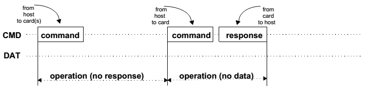
As can be seen from the figure, if we (the host) need to send a command that does not require a response - just send it. If, however, the team implies a certain answer, a helmet, and then we wait for an answer. Almost all commands and responses are checked by a checksum, both on the host side and on the card side. Well, look at the format of the command:
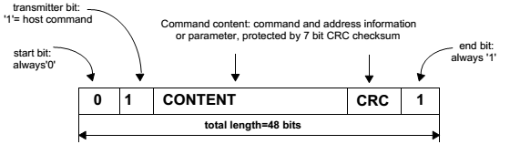
The frame consists of 48 bits. The first is the start bit - always zero. Then, we say that the data is sent from the host to the card and send a command with an argument. Yes, yes, the command consists of an index and an argument. After the command, we must send the 7-bit checksum calculated by the cyclic redundancy check (CRC) algorithm and complete the sending of the stop bit. There are two types of commands: CMD (basic commands) and ACMD (Application-Specific Command). They can be with or without argument, have a response and not have. In total there are about 80 teams (I didn’t think for sure, maybe more) and each of them is described in detail in the specification. We will focus only on a few necessary for the main work with the card (initialization, reading, writing). The team index is the number that comes after the CMD or ACMD characters. 6 bits and 32 bits of the command argument are allocated for it, if required.
An important explanation about ACMDs : the space of their indexes intersects with the indexes of CMD commands, so that the controller takes the command exactly as Application-Specific, it must be preceded by CMD55 !
The response (if required) is also a whole topic, if only because there are five types of them.
•R1 (normal response command) - length 48 bits. Perhaps the most popular response.

It contains the start bit, the transfer direction bit (from the card to the host), 6 bits of the index of the command that prompted the generation of the response, the status of the card, and, of course, the checksum with the stop bit. All information in the response of this type is carried by a 32-bit card status field . The specification carefully and conscientiously describes what each bit of this status means (the card is busy / free, locked / unlocked, the current state of the data transfer machine, readiness for a particular action, and much more).
• R1b - the same format as in the case of the R1 response, only transmits another busy flag on the data line.
•R2 (CID, CSD register) - a 136-bit response sends the contents of the CID and CSD registers of the card controller to the host.

Here, all the useful information is contained in a 127-bit field, which contains either the contents of the CID (in case it is a response to the CMD2 or CMD10 command) or the contents of the CSD register (in case of sending the CMD9 command). So what kind of registers are such that special teams were invented for them, and even with such a long response?
CID (Card identification data) - as the name implies, contains all the identification information about the card (serial number, manufacturer, date of manufacture, etc. ...). CSD (Card-specific data)- all technical information about the card (memory size, size of read / write blocks, maximum speed characteristics, maximum characteristics of current consumption in various modes, and much more). It is this information that the host of the mobile or camera uses to obtain all the information about the inserted card.
• R3 - 48 bits long, comes as a response to the ACMD41 command and carries information about the contents of the OCR (Operation Conditions Register) of the card register.

ACMD41 - card initialization command. After sending it, you must wait for this response, which will indicate the successful completion of the initialization process and report the contents of the OCR register (available voltage range, type of memory card, and busy flag).
•R6 (Published RCA response) - contains RCA (Relative card address) cards and some status bits.
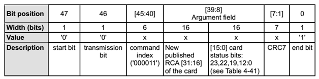
A bus involves connecting multiple cards to a single host. Therefore, such a concept as a card’s own address on the bus is very important. This is the contents of the RCA register.
• R7 (Card interface condition) - 48 bit response to the CMD8 command.

The card operates with a certain voltage, no more no less. Prior to initialization, it is necessary to validate (more on this later). In response, the card sends the voltage itself (more precisely, the value corresponding to this range) and a certain check pattern (more about this later).
2) Data.
Let me remind you (it was said a long time ago ...), we considered sending commands and receiving feedback from the card. Now is the time to figure out how to send, in fact, data. I repeat, this is done in blocks of 512 bytes (for SDHC cards) - the entire address space of the card is divided into 512 byte cells . Sending data must always be preceded by a special command telling the card controller that the data is about to go. And they go, as I said - on a 1- or 4-bit bus. Let's look at the format of sending data to the host from the card (reading).
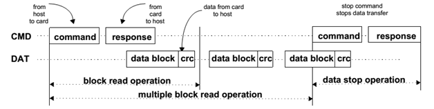
Two data transfer modes are possible: one block (block read operation) and several blocks at once (multiple block read operation). In any case, the start of the transfer and its completion occur on a special command, please note with a response.
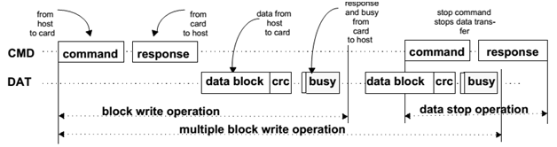
The reverse procedure (recording) is carried out in a similar way, only busy packets are necessarily present between the packets, signaling that the card is not ready to accept the next block (data has not yet been written to the flash card).
Initializing SD Memory Cards
Well, we, embedders, people are used to the fact that everything needs to be initialized, so the SD card is no exception to this magnificent rule. It is necessary to check the supported voltages, assign addresses, and in general, make sure that we can work with this card. Let's look at the initialization algorithm pulled out of the specification and go through it in order, block by block, in order to understand what needs to be done with the device before using it for its intended purpose.
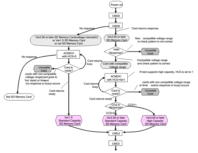
IMPORTANT : initialization is carried out at low speed! Card shred frequency is not more than 400 kHz !!!
MORE IMPORTANT: after applying power, do not rush to load the card with commands, let the voltage settle down, wait for 250 milliseconds (you can take a little longer, depending on the number of cards connected to one bus, the width of the data line and the parameters of the power supply). As soon as the voltage reached the required level, all stray capacitances, etc., were charged. etc., you can create the initialization process. And it starts with zeroing all the cards and transferring them to Idle State.
• Helmet CMD0 , pay attention, without an argument and do not expect anything in the response. As a result, all cards on the line will be idle.
• Remember, I said that stress needs to be validated? Right! You need to tell the card on which voltage we work and listen to everything about it from it. Helmet CMD8with an argument in which bits 11: 8 indicate the host voltage and bits 7: 0 - check pattern - any, the specification recommends sending 10101010 . Voltage bits are set in accordance with the table:

Well, everything is very well defined and far from the Low Voltage Range. Stm32f4 produces just the voltage in the range 2.7 - 3.6 V, so put 1 on the eighth bit of the argument. Total, we have a command with argument 110101010 . Sent. We checked that everything went well and we are waiting for an answer, it will not make us do this for a long time. In the specification, they saw that the answer to this command is R7 type.
If we did not wait for it, then the further command ACMD41decides how we were cheated - slipped a card version 1.X standard capacity or not an SD card. True, there is a possibility that we are just doing something wrong. But let's not talk about sad things, and suppose that the flash drive still answered. If everything is fine with the voltage, the card is happy, we are happy, the answer will contain everything that we sent in the argument, that is 110101010 . This is called valid esponse . If so, we proceed to the next step, otherwise - again - either cheated, or somewhere jamb.
• Waited 110101010 , and the time has come for immediate initialization - ACMD41 commands . And here we recall the IMPORTANCE :to tell the card that the command is not simple, but ACMD, we will first send CMD55 . In the argument, we must indicate the address of the card for which this command is intended. But stop, we have, because, as long as there is no address, we do not know him. Nothing, we find out ... but later, but for now we write zeros and a helmet. Having received a response of type R1 , we make sure that the card is ready to accept ACMD and only after that helmet 41 index! The command comes with an argument in which we specify 1 at the place of the 30th bit, which indicates that the host supports SDHC cards and the host voltage is 23: 0 bits in place (see the contents of the OCR register). The answer is waiting for the R3 type. Here it is important for us to get 1 in place of the 31stbits in the response packet carrying the contents of the OCR of the card register (busy flag). This will indicate that the card has completed the initialization process. In view of the fact that this process takes a long time (much longer than the clock cycle of the microcontroller), it is necessary to send ACMD41 in a cycle until we get an answer with the busy flag cleared. As soon as this happened, the check is 30 bits long, and if it is one, then we have an SDHC or SDXC high-capacity card, and a standard-capacity SD card otherwise. If we waited, waited, and the bisi flag kept hanging and hanging, then, as in the case described above, either an unsuitable card, or (most likely) our cant.
• Next helmet CMD2 - no argument and look at the answer R2. In this case, it will carry information about the contents of the CID register, and we can subtract the manufacturer ID, serial number of the card and other information.
• And finally, the final step is to obtain a card address ( RCA - relative
address ). As it was already mentioned, several cards can be connected to one bus, so each one must have its own unique local address. We send a CMD3 helmet and get an answer like R6 , in which the lower 16 bits contain the status of the card, and the higher bits contain a new RCA address. From now on, to access our card, we will have to call her by name, that is, by RCA address.
• Optional item. By default, the card works with a 1-bit data bus, which, of course, is slower than with a 4-bit one. If we want to achieve maximum performance - the ACMD6 helmet , with the previous CMD55 , of course. But first, you need to put the card in the Transfer State state (see below) with the CMD7 command with RCA as an argument. In the ACMD6 argument , in place of the very first bit, write 1 - if we want to enable the 4-bit mode and 0 - to disable it. Answer R1 will indicate the successful operation.
Example SDHC card initialization
This example uses a makeshift command sending function written to the periphery of Stm32F4.
char SDIO_send_command(char index, unsigned int arg, char resp_type, unsigned int *resp); • index - team index;
• arg is an argument;
• resp type - response type (0 - no response, 1 - short (48 bit) response, 2 - long (136 bit) response);
• resp - response array (in the case of a short response, information is carried by the first element of the array, in the case of a long response - 4 elements).
• The command returns 0, in case of a successful operation, sending a command and receiving a response, and an error code otherwise.
char SDHC_card_initialization(unsigned int *RCA)
{
	char result;
	unsigned int RESP[4];
	result = SDIO_send_command(0, 0, 0, RESP);     //Посылаем CMD0, дабы обнулить карты
	if (result != 0) return result;      //Чекаем на успех
	result = SDIO_send_command(8, 0x1AA, 1, RESP);      //Посылаем CMD8 с аргументом 110101010
	if ( (result != 0) || (RESP[0] != 0x1AA) ) return 4;      //Чекаем на успех
	while( !(RESP[0]&(1<<31) ) )      //Ждем, пока флаг бизи не слезет
	{
		result = SDIO_send_command(55, 0, 1, RESP);      //Шлем CMD55, тем самым, говоря, что потом будет ACMD
		if (result != 0) return result;
		result = SDIO_send_command(0x29, 0x40020000, 1, RESP);     //Шлем ACMD41
		if (result != 0) return result;
	}
       result = SDIO_send_command(2, 0, 3, RESP);     //Шлем CMD2 и получаем инфу о карте
	if (result != 0) return result;
	result = SDIO_send_command(3, 0, 1, RESP);     //Шлем CMD3 и получаем RCA номер
	if (result != 0) return result;
	SDIO->CLKCR = (0x02<<0)|(1<<11)|(1<<8)|(1<<14);     //Наращиваем клок (в части 2 - подробнее)
	*RCA = ( RESP[0] & (0xFFFF0000) );      //Маскируем отклик и получаем RCA
	result = SDIO_send_command(7, *RCA, 1, RESP);     //Выбираем нашу карту
	if (result != 0) return result;
	result = SDIO_send_command(55, *RCA, 1, RESP);      //Шлем CMD55, тем самым, говоря, что потом будет ACMD
	if (result != 0) return result;
	result = SDIO_send_command(6, 0x02, 1, RESP);      //Шлем ACMD6 c аргументом 0x02, установив 4-битный режим
	if (result != 0) return result;
	if (RESP[0] != 0x920) return 1; else return 0;    //Убеждаемся, что карта находится в готовности работать с трансфером
	return 0;
}
We run the code, make sure that the answer is ZERO and complete the initialization. Everything, we can work with memory and write / read information.
Data exchange
Here everyone drives the SD Memory Card State Diagram (data transfer mode).

There are 6 card statuses in this mode, and you can find them in the R1 response at 12: 9 bits. Turn to the specification.

• Stand by State (stby) - set after initialization instead of Idle State.
• Transfer State (tran) - data transfer mode.
• Receive Data State (rcv) - waiting for a packet of data from the host.
• Programming State (prg) - record the received burst in flash.
• Sending Data State (data) - sending a packet of data to the host.
•Disconnect State (dis) - used to select another card with the CMD7 command.
Writing data to a card
So, after successful initialization, we are in a state of tran , in any case, we must be. We look at the diagram: in order to switch to the rcv state , you need to send the CMD24 command with the address of the 512 byte cell that we want to write. Sent. The card went into data standby mode. Next, we start throwing information on the data bus to it until we transfer all 512 bytes or send the CMD12 command (stop transmission). After the act is completed, the card itself will move to prg state and stay there for a while (until the data is written). We are waiting ... How exactly are we waiting? And we send her in the CMD13 cycle with the address of the card in the argument, until the status tran is returned in the response R1. When this finally happened, you can send another packet of data by sending CMD24 again. In addition, there is also a recording mode for several blocks at once (CMD25) and other modes - for details - in the specification.
Reading data
In order to perform the reverse procedure, first of all, we make sure that the card is in tran . CMD17 helmet with RCA address in argument. If everything goes well, the card will move to the data state and begin to issue information on the data line, again with a 512 byte block. The task of the host at this time is to listen carefully to the line and read the data. As soon as the package is over, the card itself will move to the tran status . I think it’s not necessary to say that reading as well as writing is possible with several blocks at once.
I will not list the reader / writer in this article, because, unlike the initialization subroutine, it is too much tied to the hardware of the SDIO module of the Stm32f4 microcontroller, and this is the topic of the second part of the article.
References:
1) SD_Physical_Layer_Spec 2.0
2) SD_Physical_Layer_Spec 4.1
3) STM32F4 CortexM4 Reference manual