February 4, 2014 at 11:26
Creating a game in front of your eyes - Part 2: Shaders for styling pictures under CRT / LCD
- Tutorial
Let's talk about technology this time. In this article I will tell and show how to create a shader in Unity for styling graphics for old CRTs. Such a shader is suitable for pixel art and for styling a picture with an ancient technique. They should not be abused, but sometimes it can be used to the place. (I’ll specifically clarify - I do not propose to use such an effect constantly. But, for example, in splash screens - it may come to a place).
And immediately make a reservation - I do not have a deep understanding of shaders, but I expect even less from the reader. So I’ll write from the calculation that you don’t know anything about shaders, or almost nothing. And yes, I’ll try to explain to you the very bases of the work of shaders, so if you don’t know anything about them - welcome!
Here you need to know the following: a shader is a small program that runs on the graphics card processor for each vertex (vertex shaders) and for each rendered pixel (pixel or “fragmental” shaders).
In fact - even just pulling a texture onto a triangle is a shader. In such a shader, the vertex part of it is engaged in calculating the vertices of the triangle, and the pixel part directly in rendering the texture pixels. And, accordingly, a shader is called to draw each pixel. Moreover, they can work in parallel.
In Unity, you can use different shader languages, but I recommend CG, because it compiles fine in both OpenGL and DirectX. Accordingly, we do not need to write two different shaders.
Now, the next moment - to implement post-processing of the image (which is exactly what we planned) - we need to write not the shaders for the sprites themselves, but the general shader for the entire screen. More precisely, the render will be directed first to the texture, and this texture already using the shader will be drawn on the screen. And yes, for this we need the Pro version of the Unity package.
The first thing we need is to learn how to create a shader for the entire camera, which does not change anything.
To do this, create a new shader (file with the .shader extension) and copy this disc there:
I will explain the main points:
Left just a little bit. We need to apply a shader to the camera.
To do this, create another control script in C #:
It remains only to throw it on the camera and specify our shader in the "shader" field.
How to understand that this business works? Try to
So, we figured out the shaders.
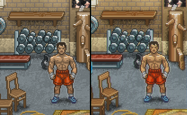
What do we want to achieve? To begin with, let's try to realize the effect when the image consists of color RGB pixels. That is, this:
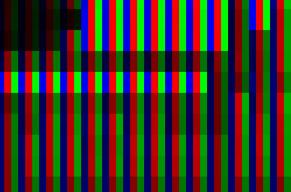
How to do it is pretty obvious. It is necessary to leave only the R, G and B component for each pixel on the screen with a cycle of 3 pixels.
Task number 1 - to get the screen coordinates of the current point in the pixel shader.
To do this, we will need to count something in the vertex shader and forward this thing to the pixel one. As mentioned above, for the exchange of data between the vertex and pixel shaders, there is a design
and also add a line to the vertex shader:
Now in the pixel shader we get the screen coordinate in the range from (0 ... 1). We need pixels. This is also done simply:
Hurrah! In
We get something like this:

Two points are immediately apparent - firstly, the effect turned out to be very strong, and secondly, the picture became darker. Thank God, having corrected the first, the second will also be corrected.
I propose not making a strict separation according to R / G / B, but in any case leaving all the components, just in different proportions. That is, in the “red” column leave 100% R, and about 50% G and B. And even better if we can customize this business.
In fact, our conversion can be done by multiplying the color by a certain multiplier. To leave only R, we need to multiply
To begin with, add a description of two parameters to the very beginning of the shader:
then write the links:
Now go to the pixel shader code and manipulate the color:
It remains only to learn how to manage these parameters in Unity. Let's write them in our C #:
And in the OnRenderImage method, add before Graphics.Blit:
Here I subtract from 1 to make it more visual. The larger the parameter, the stronger the dimming of the column.
If you did everything correctly, then in the Unity inspector when choosing a camera, you should see the sliders:

Now let's look at the effect:

Better, but still want brightness. Let's add brightness and contrast adjustments to our shader.
C # script:
Result:
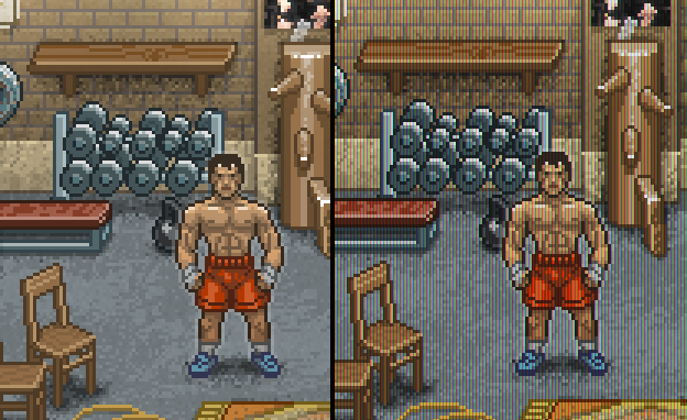
(contrast = 2.1, brightness = 27)
Now let's implement scanlines. Everything is simple here. Every 3rd row needs to be darkened.
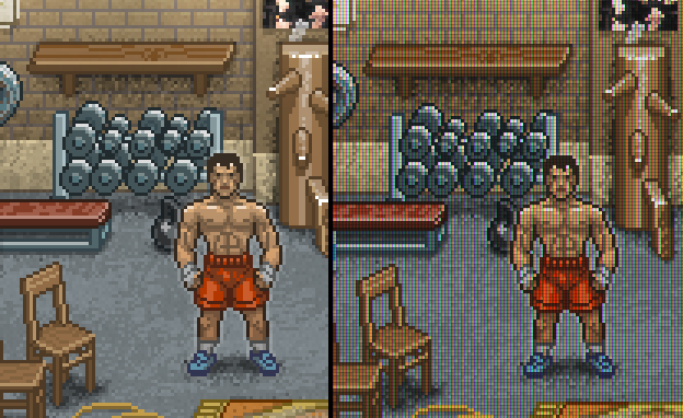
And the final touch is the Bloom effect. You can take such a shader, for example, here .
Done! We get a picture from the top of the article!
Yes, and of course - this shader will look best on a triple pixel, as in my examples.
UPD : As suggested in the comments below, you can solve this whole problem by simply multiplying one texture by another. Those. according to the specified parameters of the intensity of the bands, we render the texture-template, and then perform the multiplication. It will be faster in terms of speed, but the goal of this article was not to write the optimal shader, but to show the general principle.
All articles in the series:
And immediately make a reservation - I do not have a deep understanding of shaders, but I expect even less from the reader. So I’ll write from the calculation that you don’t know anything about shaders, or almost nothing. And yes, I’ll try to explain to you the very bases of the work of shaders, so if you don’t know anything about them - welcome!
What are shaders and how do they work?
Here you need to know the following: a shader is a small program that runs on the graphics card processor for each vertex (vertex shaders) and for each rendered pixel (pixel or “fragmental” shaders).
In fact - even just pulling a texture onto a triangle is a shader. In such a shader, the vertex part of it is engaged in calculating the vertices of the triangle, and the pixel part directly in rendering the texture pixels. And, accordingly, a shader is called to draw each pixel. Moreover, they can work in parallel.
Important remark. Each shader reads input parameters and gives output. At what, it happens in any order. In modern cards, a large number of shader threads that can be launched in parallel. That is, when one shader processes the pixel at the coordinates (0, 0), the other at the same moment can calculate the pixel at the coordinates (10, 10).
Thus, when processing a pixel in (0, 1), the shader does not know (and does not have access) to the result of processing the pixel (0, 0). It can only refer to the original value. Therefore, if you need to apply several effects depending on each other sequentially, you will most likely have to write several shaders.
In Unity, you can use different shader languages, but I recommend CG, because it compiles fine in both OpenGL and DirectX. Accordingly, we do not need to write two different shaders.
Now, the next moment - to implement post-processing of the image (which is exactly what we planned) - we need to write not the shaders for the sprites themselves, but the general shader for the entire screen. More precisely, the render will be directed first to the texture, and this texture already using the shader will be drawn on the screen. And yes, for this we need the Pro version of the Unity package.
So to battle
The first thing we need is to learn how to create a shader for the entire camera, which does not change anything.
To do this, create a new shader (file with the .shader extension) and copy this disc there:
Shader "Custom/CRTShader"
{
	Properties {
		_MainTex ("Base (RGB)", 2D) = "white" {}
	}
	SubShader {
		Pass {
			ZTest Always Cull Off ZWrite Off Fog { Mode off }
			CGPROGRAM
			#pragma vertex vert
			#pragma fragment frag
			#pragma fragmentoption ARB_precision_hint_fastest
			#include "UnityCG.cginc"
			#pragma target 3.0
			struct v2f
			{
				float4 pos      : POSITION;
				float2 uv       : TEXCOORD0;
			};
			uniform sampler2D _MainTex;
			v2f vert(appdata_img v)
			{
				v2f o;
				o.pos = mul(UNITY_MATRIX_MVP, v.vertex);
				o.uv = MultiplyUV(UNITY_MATRIX_TEXTURE0, v.texcoord);
				return o;
			}
			half4 frag(v2f i): COLOR
			{
				half4 color = tex2D(_MainTex, i.uv);
				return color;
			}
			ENDCG
		}
	}
	FallBack "Diffuse"
}
I will explain the main points:
- Properties - describes the input parameters of the shader (parameters coming from outside). At the moment, this is just a texture.
- vert - vertex shader, frag - pixel (fragmental)
- struct v2f - describes the data structure passed from vertex to pixel shaders
- uniform - creates a link from the shader language to the same parameter (s) from item 1
- In our example, the vertex shader performs a matrix operation to calculate the vertex coordinates and coordinates for the texture. Let's take it for magic that works;)
- In the same example, the pixel shader reads the texture at the coordinates received from the vertex shader ( tex2D command ) and produces the resulting color , which will be used for rendering.
- Shader languages often need multicomponent structures. For example, 3 coordinates or 4 color components. To describe them, types like float2 (meaning a structure of two floats) or, for example, int4, are used. The components can be accessed through the point .x .y .z .w or .r .g .b .a
Left just a little bit. We need to apply a shader to the camera.
To do this, create another control script in C #:
Hidden text
using UnityEngine;
[ExecuteInEditMode]
[RequireComponent(typeof(Camera))]
public class TVShader : MonoBehaviour
{
	public Shader shader;
	private Material _material;
	protected Material material
	{
		get
		{
			if (_material == null)
			{
				_material = new Material(shader);
				_material.hideFlags = HideFlags.HideAndDontSave;
			}
			return _material;
		}
	}
	private void OnRenderImage(RenderTexture source, RenderTexture destination)
	{
		if (shader == null) return;
		Material mat = material;
		Graphics.Blit(source, destination, mat);
	}
	void OnDisable()
	{
		if (_material)
		{
			DestroyImmediate(_material);
		}
	}
}
It remains only to throw it on the camera and specify our shader in the "shader" field.
How to understand that this business works? Try to
return colorwrite something like that in the shader before " " color.r = 0;and if everything is ok, then you will get a picture without red color. So, we figured out the shaders.
Getting to the implementation of the effect.
What do we want to achieve? To begin with, let's try to realize the effect when the image consists of color RGB pixels. That is, this:
How to do it is pretty obvious. It is necessary to leave only the R, G and B component for each pixel on the screen with a cycle of 3 pixels.
Task number 1 - to get the screen coordinates of the current point in the pixel shader.
To do this, we will need to count something in the vertex shader and forward this thing to the pixel one. As mentioned above, for the exchange of data between the vertex and pixel shaders, there is a design
v2f in which at the moment there are two fields - pos and uv. Add there:float4 scr_pos : TEXCOORD1;
and also add a line to the vertex shader:
o.scr_pos = ComputeScreenPos(o.pos);
Now in the pixel shader we get the screen coordinate in the range from (0 ... 1). We need pixels. This is also done simply:
float2 ps = i.scr_pos.xy *_ScreenParams.xy / i.scr_pos.w;
Hurrah! In
ps we have pixel coordinates on the screen. Then everything is quite simple. You need to write something like:int pp = (int)ps.x % 3; // остаток от деления на 3
float4 outcolor = float4(0, 0, 0, 1);
if (pp == 1) outcolor.r = color.r; else if (pp == 2) outcolor.g = color.g; else outcolor.b = color.b;
return outcolor;
We get something like this:
Two points are immediately apparent - firstly, the effect turned out to be very strong, and secondly, the picture became darker. Thank God, having corrected the first, the second will also be corrected.
I propose not making a strict separation according to R / G / B, but in any case leaving all the components, just in different proportions. That is, in the “red” column leave 100% R, and about 50% G and B. And even better if we can customize this business.
In fact, our conversion can be done by multiplying the color by a certain multiplier. To leave only R, we need to multiply
color by float4(1, 0, 0, 1)(the 4th component is alpha, we do not change it). We want to adjust the coefficients. That is, multiply the red column by (1, k1, k2, 1), the green one by (k2, 1, k1, 1), and the blue one by (k1, k2, 1, 1).To begin with, add a description of two parameters to the very beginning of the shader:
_VertsColor("Verts fill color", Float) = 0
_VertsColor2("Verts fill color 2", Float) = 0
then write the links:
uniform float _VertsColor;
uniform float _VertsColor2;
Now go to the pixel shader code and manipulate the color:
if (pp == 1) { muls.r = 1; muls.g = _VertsColor2; }
else
	if (pp == 2) { muls.g = 1; muls.b = _VertsColor2; }
	else
		{ muls.b = 1; muls.r = _VertsColor2; }
color = color * muls;
It remains only to learn how to manage these parameters in Unity. Let's write them in our C #:
[Range(0, 1)]
public float verts_force = 0.0f;
[Range(0, 1)]
public float verts_force_2 = 0.0f;
And in the OnRenderImage method, add before Graphics.Blit:
mat.SetFloat("_VertsColor", 1-verts_force);
mat.SetFloat("_VertsColor2", 1-verts_force_2);
Here I subtract from 1 to make it more visual. The larger the parameter, the stronger the dimming of the column.
If you did everything correctly, then in the Unity inspector when choosing a camera, you should see the sliders:
Now let's look at the effect:
Better, but still want brightness. Let's add brightness and contrast adjustments to our shader.
_Contrast("Contrast", Float) = 0
_Br("Brightness", Float) = 0
....
uniform float _Contrast;
uniform float _Br;
....
color += (_Br / 255);
color = color - _Contrast * (color - 1.0) * color *(color - 0.5);
C # script:
	[Range(-3, 20)]
	public float contrast = 0.0f;
	[Range(-200, 200)]
	public float brightness = 0.0f;
...
	mat.SetFloat("_Contrast", contrast);
	mat.SetFloat("_Br", brightness);
Result:
(contrast = 2.1, brightness = 27)
Now let's implement scanlines. Everything is simple here. Every 3rd row needs to be darkened.
if ((int)ps.y % 3 == 0) muls *= float4(_ScansColor, _ScansColor, _ScansColor, 1);
And the final touch is the Bloom effect. You can take such a shader, for example, here .
Done! We get a picture from the top of the article!
Yes, and of course - this shader will look best on a triple pixel, as in my examples.
UPD : As suggested in the comments below, you can solve this whole problem by simply multiplying one texture by another. Those. according to the specified parameters of the intensity of the bands, we render the texture-template, and then perform the multiplication. It will be faster in terms of speed, but the goal of this article was not to write the optimal shader, but to show the general principle.
All articles in the series:
- Idea, vision, choice of setting, platform, distribution model, etc.
- Shaders for styling pictures under CRT / LCD
- We fasten a scripting language to Unity (UniLua)
- Shader for fade in by palette (a la NES)
- Subtotal (prototype)
- Let's talk about PR indie games
- 2D animations in Unity ("like flash")
- Visual scripting of cut scenes in Unity (uScript)