Information security of bank non-cash payments. Part 8 - Typical Threat Models
- Tutorial

What research
Links to other parts of the study
- Информационная безопасность банковских безналичных платежей. Часть 1 — Экономические основы.
- Информационная безопасность банковских безналичных платежей. Часть 2 — Типовая IT-инфраструктура банка.
- Информационная безопасность банковских безналичных платежей. Часть 3 — Формирование требований к системе защиты.
- Информационная безопасность банковских безналичных платежей. Часть 4 — Обзор стандартов моделирования угроз.
- Информационная безопасность банковских безналичных платежей. Часть 5 — 100+ тематических ссылок про взломы банков.
- Информационная безопасность банковских безналичных платежей. Часть 6 — Анализ банковских преступлений.
- Информационная безопасность банковских безналичных платежей. Часть 7 — Базовая модель угроз.
- Информационная безопасность банковских безналичных платежей. Часть 8 — Типовые модели угроз (Вы здесь)
This article completes the cycle of publications devoted to ensuring the information security of bank cashless payments. Here we look at typical threat models that were referenced in the base model :
- Typical threat model. The network connection .
- Typical threat model. Information system built on the basis of client-server architecture .
- Typical threat model. Access control system .
- Typical threat model. Integration module .
- Typical threat model. The system of cryptographic protection of information.
HABRO-WARNING !!! Dear habrovchane, this is not an entertainment post.
Hidden under the cut 40+ pages of materials designed to help in work or school for people specializing in banking or information security. These materials are the final product of the study and are written in a dry official tone. In essence, these are blanks for internal security documents.
Well, the traditional - "the use of information from the article for illegal purposes is punishable by law . " Productive reading!
Information for readers who are familiar with the study, starting with this publication.
What research
You are reading the guide for the specialist responsible for ensuring the information security of payments in the bank.
The logic of presentation
At the beginning of Part 1 and Part 2 describes the object of protection. Then part 3 describes how to build a protection system, and talks about the need to form a threat model. In Part 4 describes what models are the threats and how they are formed. In part 5 and part 6 provides an analysis of actual attacks. Part 7 and Part 8 contain a description of the threat model, built on the basis of information from all previous parts.
TYPICAL MODEL OF THREAT. NETWORK CONNECTION
Protection object for which the threat model is applied (scope)
The object of protection is data transmitted via a network connection operating in data networks built on the basis of the TCP / IP stack.
Architecture
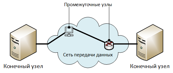
Description of architectural elements:
- “End nodes” are nodes that exchange protected information.
- “Intermediate Nodes” - elements of a data transmission network: routers, switches, access servers, proxy servers, and other equipment — through which the traffic of a network connection is transmitted. In general, a network connection can function without intermediate nodes (directly between the end nodes).
Top level security threats
Decomposition
U1. Unauthorized familiarization with the transmitted data.
Y2. Unauthorized modification of transmitted data.
Y3 Infringement of authorship of transmitted data.
U1. Unauthorized familiarization with the transmitted data
Decomposition at
1.1. <...> carried out on terminal or intermediate nodes:
1.1.1. <...> by reading the data while it is in the node’s storage devices:
U1.1.1.1. <...> in RAM.
Explanatory notes for 1.1.1.1.
For example, during the processing of the network stack node.
D1.1.1.2. <...> in non-volatile memory.
Explanations for 1.1.1.2.
For example, when storing transmitted data in cache, temporary files, or paging files.
D1.2. <...> carried out on third-party data transmission network nodes:
D1.2.1. <...> method of capturing all packets that fall on the network interface of the node:
Explanations for D1.2.1.
All packets are captured by putting the network card in promiscuous mode (promiscuous mode for wired adapters or monitor mode for wi-fi adapters).
D1.2.2. <...> by implementing man-in-the-middle (MiTM) attacks, but without modifying the transmitted data (not counting the overhead of the network protocols).
D1.2.2.1. Reference: "Typical Threat Model." Network connection Y2. Unauthorized modification of transmitted data . "
H1.3. <...>, carried out due to leakage of information on technical channels (TKUI) from physical nodes or communication lines.
D1.4. <...>, carried out for installation on the final or intermediate nodes of special technical means (ITS), intended for covert information retrieval.
Y2. Unauthorized modification of transmitted data
Decomposition
U2.1. <...> carried out on terminal or intermediate nodes:
D2.1.1. <...> by reading and making changes to the data while they are in the storage devices of the nodes:
У2.1.1.1. <...> in memory:
У2.1.1.2. <...> in non-volatile memory:
U2.2. <...>, carried out on third-party data transmission network nodes:
У2.2.1. <...> by
launching man-in-the-middle (MiTM) attacks and redirecting traffic to the attacker's node: У2.2.1.1. Physical connection of equipment intruders in the network connection gap.
U2.2.1.2. The implementation of attacks on network protocols:
U2.2.1.2.1. <...> VLAN
Management : V2.2.1.2.1.1.VLAN hopping .
U2.2.1.2.1.2. Unauthorized modification of VLAN settings on switches or routers.
U2.2.1.2.2. <...> traffic routing:
D2.2.1.2.2.1. Unauthorized modification of the static routing tables of routers.
U2.2.1.2.2.2. The attackers announced fraudulent routes through dynamic routing protocols.
U2.2.1.2.3. <...> automatic configuration:
U2.2.1.2.3.1. Rogue DHCP .
U2.2.1.2.3.2. Rogue WPAD .
U2.2.1.2.4. <...> addressing and name resolution:
U2.2.1.2.4.1. ARP spoofing .
U2.2.1.2.4.2. DNS spoofing .
U2.2.1.2.4.3. Making unauthorized changes to local host name files (hosts, lmhosts, etc.)
Y3 Violation of the authorship of the transmitted data
Decomposition
Q3.1. Neutralization of mechanisms for determining the authorship of information by specifying false information about the author or source of data:
D3.1.1. Change the information about the author contained in the information transmitted.
V3.1.1.1. Neutralization of cryptographic protection of integrity and authorship of transmitted data:
U3.1.1.1.1. Reference: "Typical Threat Model." The system of cryptographic protection of information.
E4 Creation of an electronic signature of a legitimate signatory under false data ” .
V3.1.1.2. Neutralization of the protection of the authorship of the transmitted data, implemented using one-time confirmation codes:
D3.1.1.2.1. SIM swap .
Q3.1.2. Change information about the source of information transmitted:
Q3.1.2.1. IP spoofing .
Q3.1.2.2. MAC spoofing .
TYPICAL MODEL OF THREAT. INFORMATION SYSTEM BUILT ON THE BASIS OF ARCHITECTURE CLIENT SERVER
Protection object for which the threat model is applied (scope)
The object of protection is an information system built on the basis of the client-server architecture.
Architecture

Description of architectural elements:
- "Client" is the device on which the client part of the information system functions.
- “Server” is the device on which the server part of the information system functions.
- “Data Warehouse” is a part of the information system's server infrastructure intended for storing data processed by the information system.
- "Network connection" - a channel for the exchange of information between the Client and the Server, passing through a data network. A more detailed description of the element model is given in the “Typical Threat Model. Network connection .
Restrictions
When modeling an object, the following restrictions are set:
- The user interacts with the information system within finite time intervals, called work sessions.
- At the beginning of each session, the user is identified, authenticated and authorized.
- All protected information is stored on the server side of the information system.
Top level security threats
Decomposition
U1. Perpetrators of unauthorized actions on behalf of a legitimate user.
Y2. Unauthorized modification of the protected information during its processing by the server part of the information system.
U1. Perpetrators of unauthorized actions on behalf of a legitimate user
Explanations
Usually information systems correlate actions with the user who performed them using:
- system logs (logs).
- Special attributes of data objects that contain information about the user who created or changed them.
In relation to the session, this threat can be decomposed into:
- <...> performed as part of a user session.
- <...> performed outside the user session.
User session can be initiated by:
- By the user.
- Intruders.
At this stage, the intermediate decomposition of this threat will be as follows:
1.1. Unauthorized actions were performed as part of the user session:
1.1.1. <...> set by the attacked user.
D1.1.2. <...> installed by intruders.
D1.2. Unauthorized actions performed outside of user session.
From the point of view of information infrastructure facilities that may be affected by intruders, the decomposition of intermediate threats will look like this:
| Items | Threat decomposition | ||
|---|---|---|---|
| D1.1.1. | D1.1.2. | D1.2. | |
| Customer | D1.1.1.1. | D1.1.2.1. | |
| Network connection | D1.1.1.2. | ||
| Server | D1.2.1. | ||
Decomposition at
1.1. Unauthorized actions were performed as part of the user session:
1.1.1. <...> set by the attacked user:
W1.1.1.1. The intruders acted independently from the Client:
A1.1.1.1.1 The intruders used the standard means of accessing the information system:
A1.1.1.1.1.1. The attackers used the Client’s physical I / O (keyboard, mouse, monitor, or touch screen of a mobile device):
1.1.1.1.1.1.1. The attackers acted during periods of time when the session is active, I / O facilities are available, and the user is not in place.
1.1.1.1.1.2. The attackers used remote administration tools (regular or provided by malicious code) to control the Client:
1.1.1.1.1.2.1. The attackers acted during periods of time when the session is active, I / O facilities are available, and the user is not in place.
U1.1.1.1.1.2.2. The attackers used remote administration tools whose work is invisible to the attacked user.
D1.1.1.2. The attackers substituted data in the network connection between the Client and the Server, modifying it so that they were perceived as actions by a legitimate user:
U1.1.1.2.1. Reference: “Typical Threat Model. Network connection Y2. Unauthorized modification of transmitted data . "
D1.1.1.3. Malefactors forced the user to perform the actions specified by them, using methods of social engineering.
D1.1.2 <...> installed by hackers:
D1.1.2.1. The intruders acted from the Client ( I ):
D1.1.2.1.1. The attackers neutralized the access control system of the information system:
1.1.2.1.1.1. Reference: “Typical Threat Model. Access control system. U1. Unauthorized establishment of a session on behalf of a legitimate user . "
D1.1.2.1.2. Malefactors used regular means of access of the information system
D1.1.2.2. The attackers acted from other nodes of the data transmission network, from which it is possible to establish a network connection with the Server ( I ):
D1.1.2.2.1. The attackers neutralized the access control system of the information system:
D1.1.2.2.1.1. Link:“Typical threat model. Access control system. U1. Unauthorized establishment of a session on behalf of a legitimate user . "
D1.1.2.2.2. The attackers used non-standard means of access information system.
Clarifications D1.1.2.2.2.
The attackers could install a regular client of the information system on a third-party host or could use non-standard software implementing regular communication protocols between the Client and the Server.
U1.2 Unauthorized actions performed outside the user's session.
U1.2.1 The attackers performed unauthorized actions, and then made unauthorized changes to the information system operation logs or special attributes of data objects, indicating that the actions performed by them were performed by a legitimate user.
Y2. Unauthorized modification of the protected information during its processing by the server part of the information system
Decomposition
U2.1. The attackers modify the protected information using the standard means of the information system and conduct it on behalf of the legitimate user.
B2.1.1. Reference: "Typical Threat Model." Information system built on the basis of client-server architecture. U1. Perpetrators of unauthorized actions on behalf of a legitimate user . ”
Y2.2. The attackers modify the protected information by using data access mechanisms not provided for by the standard operating mode of the information system.
U2.2.1. Malefactors modify the files containing the protected information:
У2.2.1.1. <...> using the file handling mechanisms provided by the operating system.
U2.2.1.2. <...> by provoking the recovery of files from an unauthorized modified backup.
Y2.2.2. Criminals modify the protected information stored in the database ( I ):
У2.2.2.1. The attackers neutralize the access control system DBMS:
U2.2.2.1.1. Reference: "Typical Threat Model." Access control system. U1. Unauthorized establishment of a session on behalf of a legitimate user . "
U2.2.2.2. Malefactors modify the information, using regular interfaces of a DBMS for data access.
Y2.3. The attackers modify the protected information by unauthorized modification of the algorithms of the software processing it.
U2.3.1. The source code of the software is modified.
U2.3.1. Modified software code is exposed.
Y2.4. Malefactors modify the protected information by using vulnerabilities in the software of the information system.
Y2.5. Malefactors modify the protected information during its transfer between the components of the server part of the information system (for example, the database server and the application server):
У2.5.1. Reference: "Typical Threat Model." Network connection Y2. Unauthorized modification of transmitted data . "
TYPICAL MODEL OF THREAT. ACCESS LIMITING SYSTEM
Protection object for which the threat model is applied (scope)
The protection object for which this threat model is applied corresponds to the threat model protection object: “Typical threat model. Information system built on the basis of client-server architecture. ”
The system of delimitation of user access in this threat model means a component of an information system that implements the functions:
- User identification.
- User authentication.
- User authorization.
- Logging user actions.
Top level security threats
Decomposition
U1. Unauthorized establishment of a session on behalf of a legal user.
Y2. Unauthorized elevation of user privileges in the information system.
U1. Unauthorized establishment of a session on behalf of a legal user
Explanations The
decomposition of this threat will generally depend on the type of user identification and authentication systems used.
In this model, only the user identification and authentication system using text login and password will be considered. In this case, we assume that the username is publicly available information known to attackers.
Decomposition at
1.1. <...> due to compromised credentials:
D1.1.1. Attackers compromised user credentials during storage.
Explanations D1.1.1.
For example, credentials could be written on a sticker pasted on a monitor.
D1.1.2. The user accidentally or by malicious intent gave access details to attackers.
D1.1.2.1. User recited credentials out loud while typing.
D1.1.2.2. The user deliberately transferred their credentials:
D1.1.2.2.1. <...> to colleagues.
Clarifications D1.1.2.2.1.
For example, so that they can replace it for the period of the disease.
D1.1.2.2.2. <...> to the counterparties of the employer performing work on the objects of information infrastructure.
D1.1.2.2.3. <...> to third parties.
Clarifications D1.1.2.2.3.
One, but not the only way to implement this threat is the use of social engineering methods by hackers.
D1.1.3. The attackers selected the credentials by a search method:
D1.1.3.1. <...> using standard access mechanisms.
D1.1.3.2. <...> by previously intercepted codes (for example, password hashes) for storing credentials.
D1.1.4. Attackers used malicious code to intercept user credentials.
H1.1.5. The attackers removed the credentials from the network connection between the Client and the Server:
1.1.5.1. Reference: "Typical Threat Model." Network connection U1. Unauthorized familiarization with the transmitted data . "
D1.1.6. The attackers removed the credentials from the records of work monitoring systems:
D1.1.6.1. <...> video surveillance systems (in case there were keystrokes on the keyboard during operation).
D1.1.6.2. <...> systems for monitoring employee actions behind a computer
Explanations D1.1.6.2.
An example of such a system is StuffCop .
D1.1.7. Attackers have compromised user credentials due to the shortcomings of the transfer process.
Explanations D1.1.7.
For example, the transmission of passwords in clear text by e-mail.
D1.1.8. The attackers learned the credentials by monitoring the user's session using remote administration systems.
1.1.9. The attackers recovered their credentials as a result of their leakage through technical channels (TCIS):
1.1.9.1. The attackers saw how the user enters the credentials from the keyboard:
1.1.9.1.1 The attackers were located in close proximity to the user and saw the credentials entered with their own eyes.
Clarifications W1.1.9.1.1
Such cases may include the actions of work colleagues or the case when the user's keyboard is visible to visitors of the organization.
D1.1.9.1.2 The attackers used additional technical tools, such as binoculars or unmanned aerial vehicles, and saw the entry of credentials through a window.
D1.1.9.2. The attackers removed the credentials from the records of the radio between the keyboard and the system unit of the computer in the case of connecting them over the radio interface (for example, Bluetooth).
D1.1.9.3. The attackers carried out the interception of credentials due to their leakage through the channel spurious electromagnetic radiation and interference (PEMIN).
Explanations D.1.1.3.3.
Examples of attacks here and here .
1.1.9.4. The attacker intercepted the entry of credentials from the keyboard through the use of special technical means (ITS), designed for covert information retrieval.
Explanations D.1.1.4.4.
Examples of devices .
1.1.9.5. The attackers intercepted the input of credentials from the keyboard by
analyzing the Wi-Fi signal, modulated by the keystroke process by the user.
Explanations D.1.1.5.
An example of an attack .
D1.1.9.6. The attackers have intercepted the input of credentials from the keyboard by analyzing the sounds of keystrokes.
Clarifications W1.1.9.6.
An example of an attack .
W1.1.9.7. The attackers intercepted the entry of credentials from the keyboard of the mobile device by analyzing the accelerometer readings.
Clarifications W1.1.9.7.
An example of an attack .
U1.1.10. <...> previously stored on the Client.
Explanations D.1.1.10.
For example, a user could save in the browser login and password to access a specific site.
D1.1.11. Attackers have compromised credentials due to flaws in the process of revoking user access.
Explanation D1.1.11.
For example, after the user's dismissal his user accounts remained unblocked.
D1.2. <...> by exploiting vulnerabilities in the access control system.
Y2. Unauthorized elevation of user privileges in the information system
Decomposition of
U2.1 <...> by making unauthorized changes to data containing information about the privileges of the user.
U2.2 <...> due to the use of vulnerabilities in the access control system.
Y2.3. <...> due to the shortcomings of the user access control process.
Explanations D2.3.
Example 1. The user for work was given access greater than he needed for business needs.
Example 2. After a user was transferred to another position, the previously granted access rights were not revoked.
TYPICAL MODEL OF THREAT. INTEGRATION MODULE
Protection object for which the threat model is applied (scope)
The integration module is a set of information infrastructure objects designed to organize the exchange of information between information systems.
Given the fact that in corporate networks it is not always possible to unambiguously separate one information system from another, the integration module can also be considered as a link between the components within one information system.
Architecture The
generalized scheme of the integration module is as follows:
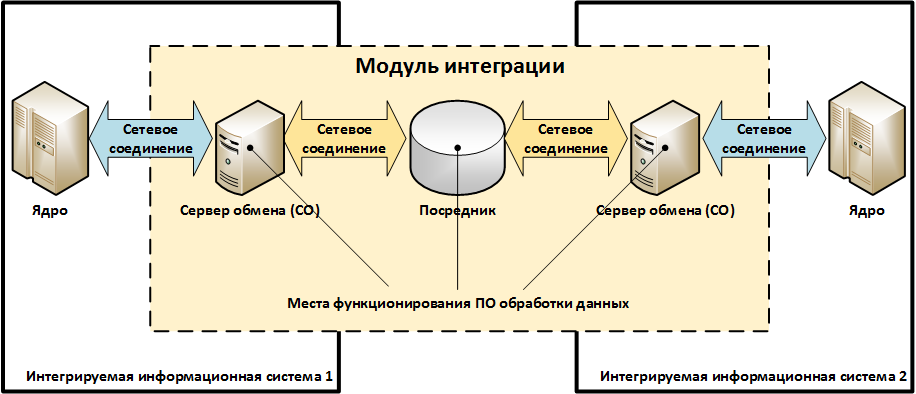
Description of the architectural elements:
- “Exchange server (CO)” is a node / service / component of an information system that performs the function of data exchange with another information system.
- “Intermediary” is a node / service intended for organizing interaction between information systems, but not included in their composition.
Examples of “Intermediaries” can be e-mail services, enterprise service buses (enterprise service bus / SoA-architecture), third-party file servers, etc. In general, the integration module may not contain “Intermediaries”. - "Data processing software" is a set of programs that implements data exchange protocols and format conversion.
For example, the conversion of data from the UBBS format to the ABS format, the change of message statuses during transmission, etc. - The “network connection” corresponds to the object described in the typical network connection threat model. Some of the network connections from those shown in the diagram above may not be.
Examples of integration modules
Scheme 1. The integration of the ABS and the automated workplace of the CBD through a third-party file server
To execute payments, an authorized bank employee unloads electronic payment documents from the ABS and saves them to a file (in its own format, for example, SQL dump) on the network folder (\\ ... \ SHARE \) file server. Then this file is converted using a converter script into a set of UBEBS format files, which are then read by the AWS of the CBD.
After that, an authorized employee - the user of the ARM CBR - encrypts and signs the received file and sends them to the payment system of the Bank of Russia.
When payments are received from the Bank of Russia, the ARM CBR performs their decoding and verification of the electronic signature, and then writes them down as a set of UBEBS format files to a file server. Before importing payment documents into ABS, they are converted with the help of a converter script from the EBRD format to the ABS format.
We will assume that in this scheme, the ABS operates on one physical server, the AWS of the CBD functions on a dedicated computer, and the script converter runs on a file server.

The correspondence of the objects of the considered scheme to the elements of the integration module model:
“Exchange server by the ABS” is the ABS server.
"Exchange servers from the ARM CBD" - computer ARM CBD.
"Mediator" - a third-party file server.
"Data processing software"- script converter.
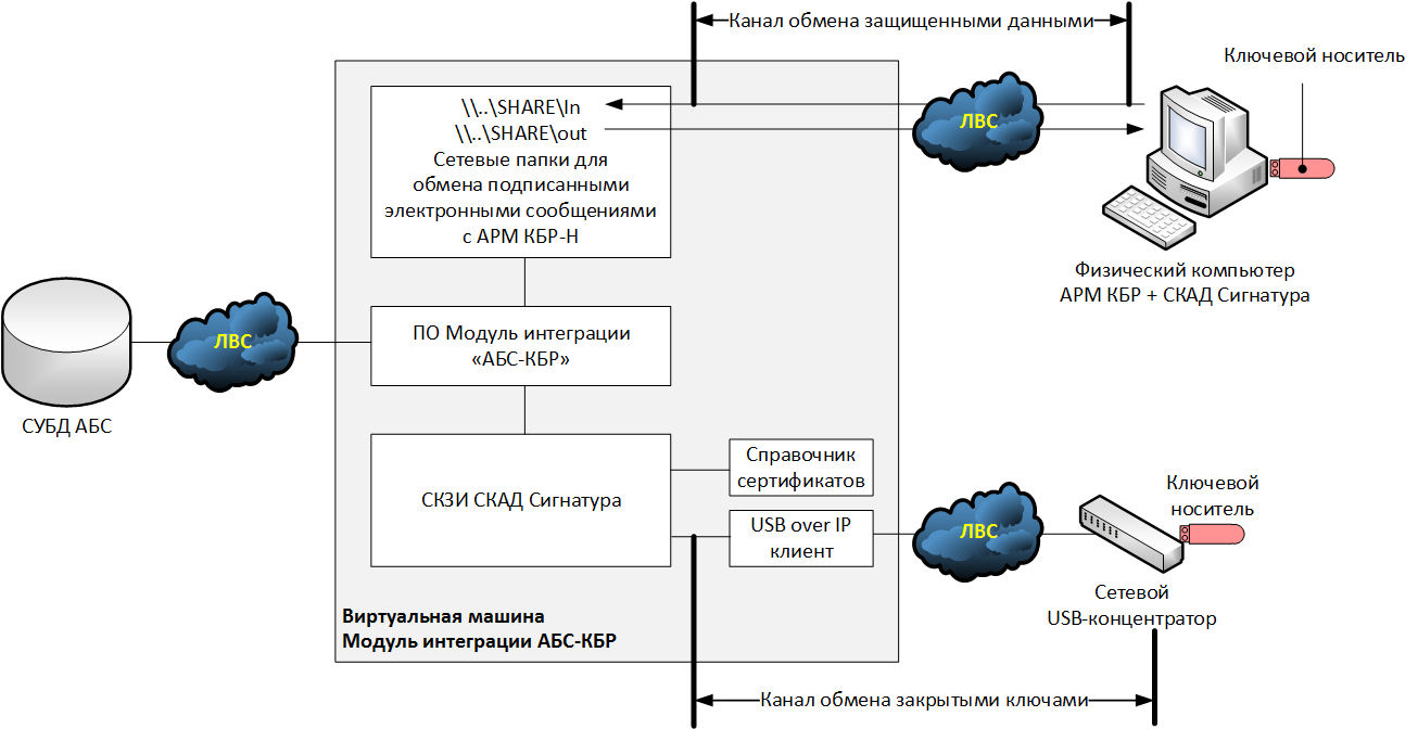
Scheme 2. Integration of the ABS and AWS of the CBD when placing a shared network folder with payments on the AWS of the CBD
Everything is the same as Figure 1, but a separate file server is not used, instead the network folder (\\ ... \ SHARE \) with electronic payment documents is placed on computer with ARM CBD. The script converter also works on the AWS CBD.

Correspondence of the objects of the considered scheme to the elements of the integration module model:
Similar to Scheme 1, but the “Mediator” is not used.
Scheme 3. The integration of the ABS and AWS CBD-N through IBM WebSphera MQ and the implementation of the signature of electronic documents "on the side of the ABS"
ABS works on a platform that is not supported by SCZD Signature. The signature of outgoing electronic documents is carried out on a special electronic signature server (ES Server). The same server verifies the electronic signature under documents from the Bank of Russia.
The ABS uploads a file with payment documents in its own format to the ES Server.
The ES server with the help of a converter script converts the file into electronic messages of the format UBEBS, after that the electronic messages are signed and transmitted to IBM WebSphere MQ.
The AWS CBD-N contacts IBM WebSphere MQ and receives signed payment messages from there, after which an authorized employee — the AWC user AWD — encrypts them and sends them to the Bank of Russia payment system.
When payments are received from the Bank of Russia, the AWS KBR-N decrypts them and verifies the electronic signature. Successfully processed payments in the form of decrypted and signed electronic messages of the UBEBS format are transmitted to IBM WebSphere MQ, from where they are received by the ES Server.
The ES server verifies the electronic signature of incoming payments and saves them to the file of the ABS format. After that, an authorized employee - an ABS user - uploads the resulting file to the ABS in the prescribed manner.
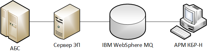
The correspondence of the objects of the considered scheme to the elements of the integration module model:
“Exchange server by the ABS” is the ABS server.
"Exchange server from the ARM CBD" - computer ARM CBD.
“Intermediary” - ES Server and IBM WebSphere MQ.
"Data processing software"- script converter, SKZI SCAD Signature on the VC Server.
Scheme 4. Integration of the RB and ABS Server through the API provided by a dedicated exchange server.
We assume that the bank uses several remote banking service systems (DBOs):
- "Internet Client-Bank" for individuals (ICB FL);
- "Internet Client-Bank" for legal entities (ICB LE).
In order to ensure information security, the entire interaction of the ABS with the RBS systems is carried out through a dedicated exchange server that operates within the ABS information system.
Next, we consider the process of interaction between the DBO IKB LE and the ABS system.
The RBS server, having received a duly certified payment order from the client, should, on its basis, create a corresponding document in the ABS. To do this, it uses the API to transmit information to the exchange server, and the latter, in turn, enters the data in the ABS.
When the balances on the client's account change, the ABS generates electronic notifications, which are transmitted to the RBS server using the exchange server.
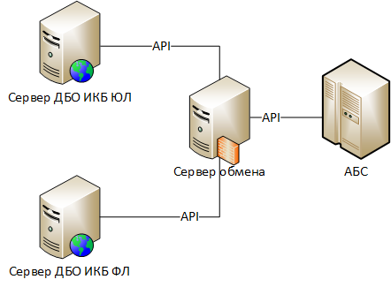
The correspondence of the objects of the considered scheme to the elements of the integration module model:
“Exchange server by the RB” is the RB of the IKB UL.
"Server exchange by the ABS" - server exchange.
“Mediator” is absent.
“Data processing software” is the RBS Server components responsible for using the exchange server API, the exchange server components responsible for using the ABS API.
Top level security threats
Decomposition
U1. The introduction of counterfeit information by intruders through the integration module.
U1. The introduction of false information by the attackers through the integration module
Decomposition at1.1. Unauthorized modification of legitimate data during its transfer through network connections:
A1.1.1 Reference: “Typical threat model. Network connection Y2. Unauthorized modification of transmitted data . "
D1.2. Transfer via communication channels of false data on behalf of a legitimate participant in the exchange:
D1.1.2 Reference: “Typical Threat Model. Network connection Y3 Violation of the authorship of the transmitted data . "
H1.3. Unauthorized modification of legitimate data when it is processed on the Exchange Servers or the Intermediary:
D1.3.1. Link:“Typical threat model. Information system built on the basis of client-server architecture. Y2. Unauthorized modification of the protected information during its processing by the server part of the information system " .
D1.4. Creating fake data on the Exchange Servers or the Intermediary on behalf of the legitimate participant in the exchange:
D1.4.1. Reference: "Typical Threat Model." Information system built on the basis of client-server architecture. U1. Perpetrators of unauthorized actions on behalf of a legitimate user. ”
V1.5. Unauthorized modification of data during their processing using data processing software:
У1.5.1. <...> by introducing unauthorized changes in the settings (configuration) of the data processing software by the attackers.
D1.5.2. <...> by introducing unauthorized changes by hackers into the executable files of the data processing software.
D1.5.3. <...> due to the interactive management of data processing software by malicious users.
TYPICAL MODEL OF THREAT. SYSTEM OF CRYPTOGRAPHIC PROTECTION OF INFORMATION
Protection object for which the threat model is applied (scope)
The object of protection is a system of cryptographic protection of information used to ensure the security of an information system.
Architecture
The basis of any information system is the application software (software) that implements its target functionality.
At the same time, cryptographic protection is usually implemented by calling cryptographic primitives from the business logic of the application software, which are located in specialized libraries - crypto cores.
The cryptographic primitives include low-level cryptographic functions, such as:
- encrypt / decrypt the data block;
- create / check the electronic signature of the data block;
- calculate the hash function of the data block;
- generate / upload / upload key information;
- etc.
The business logic of the application software using cryptographic primitives implements a higher-level functionality:
- encrypt the file on the keys of the selected recipients;
- establish a secure network connection;
- inform about the results of verification of electronic signature;
- etc.
The interaction of business logic and crypto core can be done:
- directly, by calling the business logic of cryptographic primitives from the dynamic libraries of the crypto core (.DLL - for Windows, .SO - for Linux);
- indirectly, through cryptographic interfaces - wrappers, for example, MS Crypto API, Java Cryptography Architecture, PKCS # 11, etc. In this case, the business logic refers to the cryptointerface, and that translates the call to the corresponding crypto core, which in this case is called crypto-provider. The use of cryptographic interfaces allows the application software to abstract from specific cryptographic algorithms and be more flexible.
Two typical schemes of organization of a crypto-core can be distinguished:
Scheme 1 - Monolithic crypto-core

Scheme 2 - Separated crypto-core

Elements on the above diagrams can be either separate software modules running on the same computer or network services that interact within a computer network.
When using systems built according to scheme 1, the application software and the crypto-core work within the framework of a unified environment for the functioning of crypto-tools (SFC), for example, on the same computer, running the same operating system. The user of the system, as a rule, can run other programs within the framework of the same operating environment, including those containing malicious code. Under such conditions, there is a serious risk of leakage of closed cryptographic keys.
To minimize the risk, apply scheme 2, in which the cryptokernel is divided into two parts:
- The first part together with the application software works in an untrusted environment where there is a risk of infection by malicious code. We will call this part - "the software part."
- The second part works in a trusted environment on a dedicated device, which contains a private key storage. Further we will call this part - “hardware”.
The division of a crypto core into software and hardware is very conditional. There are systems on the market that are built according to a scheme with a divided cryptokernel, but the “hardware” part of which is represented as a virtual machine image — virtual HSM ( example ).
The interaction of both parts of the crypto-kernel occurs in such a way that the private cryptographic keys are never transferred to the software part and, accordingly, cannot be stolen with the help of malicious code.
The interaction interface (API) and the set of cryptographic primitives provided by the application software to the crypto-core are the same in both cases. The difference lies in the way they are implemented.
So, when using a scheme with a divided cryptokernel, the interaction of the software and hardware is performed according to the following principle:
- Cryptographic primitives that do not require the use of a private key (for example, calculating a hash function, checking electronic signatures, etc.) are performed by the software part.
- Cryptographic primitives using the private key (creating an electronic signature, decrypting data, etc.) are performed by the hardware.
We illustrate the work of a divided cryptokernel using the example of creating an electronic signature:
- The software part calculates the hash function of the data to be signed and passes this value to the hardware through an exchange channel between crypto-cores.
- The hardware, using the private key and the hash, generates the value of the electronic signature and transfers it to the program part via the exchange channel.
- The software part returns the resulting value to the application software.
Features of the verification of the electronic signature
When the receiving party receives the data signed by the electronic signature, it must carry out several stages of verification. A positive result of the verification of an electronic signature is achieved only with the successful completion of all stages of verification.
Step 1. Control data integrity and data authorship.
The content of the stage. An electronic signature of the data is verified using the appropriate cryptographic algorithm. Successful completion of this stage indicates that the data has not been modified since it was signed, as well as the fact that the signature was made with a private key corresponding to the public key of the electronic signature verification.
Place of performance: kryptoyadro.
Step 2. Control confidence in the signer's public key and control the validity of the private key of the electronic signature.
The content of the stage. The stage consists of two intermediate sub-steps. The first establishes whether the public key of the electronic signature verification was trusted at the time of signing the data. The second establishes whether the private key of the electronic signature was valid at the time of signing the data. In general, the validity periods of these keys may not coincide (for example, for qualified certificates of electronic signature verification keys). Ways of establishing trust in the signer's public key are determined by the electronic document management rules adopted by the interacting parties.
Place of performance: application software / cryptokernel.
Stage 3. Control of the signatory's authority.
The content of the stage. In accordance with the established rules of electronic document management, it is checked whether the signatory had the right to certify the protected data. For example, we give a situation of violation of authority. Suppose there is an organization where all employees have an electronic signature. The order of the head, but signed with the electronic signature of the warehouse manager, is received into the internal electronic document management system. Accordingly, such a document can not be considered legitimate.
Place of performance: application software.
Assumptions adopted in the description of the object of protection
- Information channels, with the exception of key exchange channels, including pass through the application software, API and crypto core.
- Information about trust in public keys and / or certificates, as well as information about the powers of the owners of public keys, is placed in the public key storage.
- Application software works with a public key store through a crypto core.
An example of an information system protected by the SKZI
To illustrate the previously presented schemes, we consider a hypothetical information system and select all structural elements on it.
Description of the information system The

two organizations decided to introduce a legally significant electronic document management (EDM) among themselves. To do this, they entered into an agreement in which they stated that the documents will be transmitted by e-mail, and at the same time they must be encrypted and signed by a qualified electronic signature. Office software from the Microsoft Office 2016 package should be used as tools for creating and processing documents, and CryptoPRO and CryptoARM encryption software are used as cryptographic protection tools.
Description of the organization's infrastructure 1
Organization 1 decided that it would install the CryptoPRO CIPS and CryptoARM software on the user's AWP - a physical computer. Encryption keys and electronic signatures will be stored on the key carrier ruToken, operating in a mode of extractable key. The user will prepare electronic documents locally on his computer, after which they are encrypted, signed and sent using a locally installed email client.
Description of the organization's infrastructure 2
Organization 2 decided to put the encryption and electronic signature functions on the dedicated virtual machine. At the same time, all cryptographic operations will be performed automatically.
To do this, two network folders are organized on the dedicated virtual machine: "\\ ... \ In \", "\\ ... \ Out \". In the network folder "\\ ... \ In \" will be automatically placed received from the counterparty files in open form. These files will be decrypted and their electronic signature will be verified.
In the folder "\\ ... \ Out \" the user will place the files that need to be encrypted, signed and sent to the counterparty. The user will prepare the files on his workstation.
To perform the functions of encryption and electronic signature on a virtual machine, the cryptographic cryptographic information protection system, CryptoARM software and mail client are installed. Automatic control of all elements of the virtual machine will be carried out using scripts developed by system administrators.
The cryptographic keys of the electronic signature will be placed on the token with the non-recoverable JaCarta GOST key, which the user will connect to his local computer.
The token will be forwarded to the virtual machine using specialized USB-over-IP software installed on the user's work station and on the virtual machine.
The system clock on the user's AWP in organization 1 will be adjusted manually. The system clock of a specialized virtual machine in organization 2 will be synchronized with the system clock of the hypervisor, and those, in turn, will be synchronized via the Internet with public time servers.
Selection of structural elements SKZI
Based on the above description of the IT infrastructure, we will select the structural elements of the SKPI and write them in a table.
Table - Correspondence of the elements of the SKZI model to elements of information systems
| Item Name | Organization 1 | Organization 2 |
| Application Software | ON CryptoARM | ON CryptoARM |
| The software part of the crypto core | SKZI CryptoPRO CSP | SKZI CryptoPRO CSP |
| Hardware part of the crypto core | missing | JaCarta GOST |
| API | MS CryptoAPI | MS CryptoAPI |
| Public key store | AWP user: - hard drive; - standard Windows certificate storage. | Hypervisor: - hard drive. Virtual machine: - hard disk; - standard certificate store Windows. |
| Private Key Storage | Key carrier ruToken operating in a retrievable key mode | Key carrier JaCarta GOST, operating in non-recoverable key mode |
| Public key exchange channel | AWP user: - RAM. | Hypervisor: - RAM. Virtual machine: - RAM. |
| Private key exchange channel | AWP user: - USB bus; - RAM. | missing |
| Channel exchange between crypto cores | missing (no hardware of the crypto core) | AWP user: - USB bus; - RAM; - software module USB-over-IP; - network interface. Corporate network of the organization 2. Hypervisor: - operational memory; - network interface. Virtual machine: - network interface; - RAM; - software module USB-over-IP. |
| Open Data Channel | AWP user: - I / O; - RAM; - HDD. | AWP user: - I / O; - RAM; - HDD; - network interface. Corporate network of the organization 2. Hypervisor: - network interface; - RAM; - HDD. Virtual machine: - network interface; - RAM; - HDD. |
| Secure data channel | The Internet. Corporate network of the organization 1. User’s automated workplace: - hard disk; - RAM; - network interface. | The Internet. Corporate network of the organization 2. Hypervisor: - network interface; - RAM; - HDD. Virtual machine: - network interface; - RAM; - HDD. |
| Time channel | AWP user: - I / O; - RAM; - system timer. | The Internet. Corporate network of the organization 2, Hypervisor: - network interface; - RAM; - system timer. Virtual machine: - RAM; - system timer. |
| Control Command Transmission Channel | AWP user: - I / O; - RAM. (CryptoARM graphic user interface) | Virtual machine: - RAM; - HDD. (Automation Scripts) |
| Channel receiving results | AWP user: - I / O; - RAM. (CryptoARM graphic user interface) | Virtual machine: - RAM; - HDD. (Log files of automation scripts) |
Top level security threats
Explanations
Assumptions made when decomposing threats:
- Strong cryptographic algorithms are used.
- Cryptographic algorithms are used safely in the correct modes of operation (for example, ECB is not used to encrypt large amounts of data, allowable load on the key, etc.).
- The attackers are aware of all the algorithms, protocols and public keys used.
- Intruders can read all encrypted data.
- Malefactors are able to reproduce any program elements in the system.
Decomposition
U1. Compromise of private cryptographic keys.
Y2. Encrypt fake data on behalf of a legitimate sender.
Y3 Decryption of encrypted data by non-legitimate recipients of data (intruders).
E4 Creating an electronic signature of a legitimate signer under false data.
V5 Getting a positive result of verification of electronic signature of false data.
Y6 The erroneous acceptance of electronic documents for execution due to problems in the organization of electronic documents.
E7. Unauthorized familiarization with the protected data during their processing.
U1. Compromise of private cryptographic keys
U1.1. Getting the private key from the storage of private keys.
D1.2. Getting the private key from the objects of the environment of the functioning of the cryptographic means in which it may temporarily be.
Explanations D1.2.
Objects in which the private key can be temporarily stored will include:
- RAM,
- temporary files,
- paging files
- hibernation files
- “hot” state snapshots files of virtual machines, including the paused memory files of virtual machines.
D1.2.1. Removing private keys from working RAM by freezing RAM modules, retrieving them, and then reading data (freeze attack).
Explanations D1.2.1.
An example of an attack .
H1.3. Getting the private key from the private key exchange channel.
Explanations D1.3.
An example of the implementation of this threat will be given below .
D1.4. Unauthorized modification of a cryptokernel, as a result of which private keys become known to attackers.
V1.5. Compromise of the private key as a result of using technical information leakage channels (TKUI).
Explanations D1.5.
An example of an attack .
H1.6. Compromise of the private key as a result of the use of special technical means (ITS), intended for the secret collection of information ("bugs").
U1.7. Compromise of private keys in the process of storing them outside of SKZI.
Explanations D1.7.
For example, a user stores his key carriers in a desktop drawer, from which they can easily be extracted by intruders.
Y2. Encryption of fake data on behalf of a legitimate sender
Explanations
This threat is considered only for data encryption schemes with sender authentication. Examples of such schemes are specified in the recommendations for standardization R 1323565.1.004-2017 “Information technology. Cryptographic protection of information. Shared Key Generation Schemes with Public Key Authentication . ” For the remaining cryptographic schemes, this threat does not exist, since encryption is performed on the recipient’s public keys, and they are generally known to attackers.
Decomposition
U2.1. Compromise of the private key of the sender:
U2.1.1. Reference: "Typical Threat Model." The system of cryptographic protection of information. U1. Compromise of private cryptographic keys " .
Y2.2. Substitution of input data in the channel for the exchange of open data.
Notes U2.2.
Examples of the implementation of this threat are given below here and here .
Y3 Decryption of encrypted data by persons who are not legitimate recipients of data (intruders)
Decomposition
Q3.1. Compromise of the private keys of the recipient of the encrypted data.
V3.1.1 Reference: “Typical Threat Model. The system of cryptographic protection of information. U1. Compromise of private cryptographic keys " .
D3.2. Substitution of encrypted data in the exchange of protected data.
E4 Creating an electronic signature of a legitimate signer under false data
Decomposition
D4.1. Compromise of private keys of an electronic signature of a legitimate signer.
D4.1.1 Reference: “Typical Threat Model. The system of cryptographic protection of information. U1. Compromise of private cryptographic keys " .
Y4.2. Substitution of signed data in the open data exchange channel.
Note Y4.2.
Examples of the implementation of this threat are given below here and here .
V5 Getting a positive result of the verification of electronic signature of false data
Decomposition
У5.1. The attackers intercept the message about the negative result of the verification of the electronic signature in the transmission channel of the results of the work and replace it with a message with a positive result.
E5.2. Malefactors carry out an attack on trust to certificates of the signature ( SCENARIO - all elements are obligatory ):
У5.2.1. Attackers generate public and private key electronic signature. If the system uses certificates of electronic signature keys, they generate an electronic signature certificate as close as possible to the certificate of the intended sender of the data whose message they want to forge.
U5.2.2. Attackers make unauthorized changes to the public key store, giving the public key they generated the necessary level of trust and authority.
D5.2.3. Attackers sign fake data with a previously generated electronic signature key and embed it in the secure data exchange channel.
H5.3. The attackers carry out an attack using the overdue keys of the electronic signature of the legal signatory ( SCENARIO - all elements are required ):
У5.3.1. The attackers compromise the expired (not currently in effect) private keys of the electronic signature of the legitimate sender.
Y5.3.2. The attackers replace the time in the time transmission channel with the time at which the compromised keys still operated.
H5.3.3. The attackers sign fake data with a previously compromised electronic signature key and inject them into the secure data exchange channel.
E5.4. The attackers carry out an attack using the compromised electronic signature keys of the legal signer ( SCENARIO - all elements are required ):
У5.4.1. Malicious users make a copy of the public key store.
D5.4.2. The attackers compromise the private keys of one of the legal senders. He notices the compromise, revokes the keys, information about the revocation of the key is placed in the public key storage.
D5.4.3. Malefactors replace storage of public keys with earlier copied.
L5.4.4. The attackers sign fake data with a previously compromised electronic signature key and inject them into the secure data exchange channel.
E5.5. <...> due to the presence of errors in the implementation of the 2nd and 3rd stage of the verification of electronic signature:
Explanations У5.5.
An example of the implementation of this threat is given below .
W5.5.1. Verification of the trust to the certificate of the key of the electronic signature only by the presence of trust to the certificate with the help of which it is signed, without checking the CRL or OCSP.
Clarification W5.5.1.
An example of a threat .
Y5.5.2. When building a chain of trust to a certificate, the powers of issuing certificates are not analyzed
. Explanations У5.5.2.
An example of an attack against SSL / TLS certificates.
The attackers bought a legitimate certificate for their e-mail. Then they made a fraudulent site certificate and signed it with their certificate. If the authorization check is not performed, then when checking the chain of trust, it will be correct, and, accordingly, the fraudulent certificate will also be correct.
Y5.5.3. When building a trust chain to a certificate, intermediate certificates are not checked for revocation.
Y5.5.4. CRL updates occur less frequently than the certification authority releases them.
Y5.5.5. The decision on trust in the electronic signature is made before the OCSP response is received regarding the status of the certificate, sent on request made later than the signature generation time or earlier than the next CRL received after the signature generation.
Explanations D5.5.5.
In the regulations of most CAs, the time of certificate revocation is considered the time of issue of the nearest CRL containing information on certificate revocation.
Y5.5.6. Upon receipt of the signed data, the certificate does not verify that the certificate belongs to the sender.
Explanations D5.5.6.
An example of an attack. For SSL certificates: the address of the called server may not be checked for the value of the CN field in the certificate.
An example of an attack. Malefactors compromised keys of an electronic signature of one of participants of a payment system. After that, they broke into the network of another participant and, on his behalf, sent to the settlement server of the payment system payment documents signed by compromised keys. If the server only analyzes trust and does not verify compliance, then fraudulent documents will be considered legitimate.
Y6 The erroneous acceptance of electronic documents for execution due to problems in the organization of electronic documents.
Decomposition
V6.1. The receiving party does not detect duplication of received documents.
Explanation Q6.1.
An example of an attack. Attackers can intercept a document transmitted to the recipient, even if it is cryptographically protected, and then repeatedly send it to the protected data transmission channel. If the recipient does not detect duplicates, then all received documents will be perceived and processed as different documents.
E7. Unauthorized familiarization with the protected data during their processing SKZI
Decomposition
D7.1. <...> due to the leakage of information through third-party channels (side channel attack).
Explanation Q7.1.
An example of an attack .
D7.2. <...> due to the neutralization of the protection against unauthorized access to the information processed on the
MISP : D7.2.1. Operation of SKZI with violations of the requirements described in the documentation on SKZI.
D7.2.2. <...>, implemented in at the expense of the presence of vulnerabilities in:
D7.2.2.1. <...> means of protection against unauthorized access.
D7.2.2.2. <...> itself SKZI.
D7.2.2.3. <...> environment of functioning of cryptomechanism.
Attack examples
The scenarios considered below obviously contain errors of information security organization and serve only to illustrate possible attacks.
Scenario 1. An example of the implementation of threats Y2.2 and Y4.2.
Object Description

Software ARM CBD and SKZI SCUD Signature installed on a physical computer that is not connected to the computer network. PCF vdToken is used as the key carrier in the operation of the non-recoverable key.
The settlement procedure assumes that the settlement officer downloads electronic messages in open form (the old AWS KBR scheme) from a special protected file server, then writes them to a removable media USB flash drive and transfers them to the KBR AWS, where they are encrypted and signs After that, the specialist transfers the protected electronic messages to the alienable medium, and then, via his working computer, writes them to the file server, from where they get to the UTA and then to the payment system of the Bank of Russia.
In this case, the channels for the exchange of open and protected data will include: a file server, a specialist’s work computer, and alienable media.
Attack
Unauthorized attackers install a remote control system on a specialist’s work computer and, at the time of recording on an alienable carrier of payment orders (electronic messages) in open form, replace the contents of one of them. The specialist transfers the payment orders to the AWS of the CBD, signs and encrypts them, without noticing the substitution (for example, due to the large number of payment orders on the flight, fatigue, etc.). After that, a fake payment order, passing through the technological chain, enters the payment system of the Bank of Russia.
Scenario 2. An example of the implementation of threats Y2.2 and Y4.2.
Description of the object

Computer with installed AWS of the CBD, SCAD Signature and the key carrier connected to the PCF vdToken functions in a dedicated room without access by personnel.
The billing specialist is connected to the ARM CBD in the remote access mode via the RDP protocol.
Attack The
attackers intercept the details, using which the billing specialist connects and works with the KBR AWS (for example, through malicious code on his computer). Then they make a connection on his behalf and send a fake payment order to the payment system of the Bank of Russia.
Scenario 3. An example of the implementation of the threat of 1.1.
Description of the object
Consider one of the hypothetical options for the implementation of the ABS-KBR integration modules for the new scheme (AWS KBR-N), in which the electronic signature of outgoing documents takes place on the ABS side. At the same time, we will assume that the ABS operates on the basis of an operating system that is not supported by SCZI SCAD Signature, and, accordingly, the cryptographic functionality has been moved to a separate virtual machine - the ABS-KBR integration module.
As a key carrier, a normal USB token is used, operating in a removable key mode. When connecting the key carrier to the hypervisor, it turned out that there are no free USB ports in the system, so it was decided to connect the USB token through a network USB hub, and install a USB-over-IP client to the virtual machine that will communicate with the hub.
Attack The
attackers intercepted the private key of the electronic signature from the communication channel between the USB hub and the hypervisor (the data was transmitted in clear text). Having the private key, the attackers formed a fake payment order, signed it with an electronic signature and sent it to the AWP KBR-N for execution.
Scenario 4. An example of the implementation of threats V5.5.
Description of the object
Consider the same scheme as in the previous scenario. We assume that the emails coming from the AWS KBR-N fall into the \\ ... \ SHARE \ In folder, and those sent to the AWS KBR-N and further into the payment system of the Bank of Russia - into \\. .. \ SHARE \ out.
We will also assume that when implementing the integration module, the lists of revoked certificates are updated only when the cryptographic keys are reissued, and that the emails received in the \\ ... \ SHARE \ In folder are checked only for integrity control and trust control for the open key signature.
Attack
The attackers, using the keys stolen in the previous scenario, signed a fake payment order containing information about the receipt of money on the account of the fraudster client and inserted it into the secure data exchange channel. Since it is not the Bank of Russia that checks that the payment order is signed by the Bank of Russia, it is accepted for execution.