Autodesk Simulation CFD 2014 Quick Start Guide
- Tutorial
Good day.
It so happened that recently I had to deal with the task of calculating the thermodynamics of a heat exchanger drawn in 3D.
And after a short search, my choice fell on Autodesk Simulation CFD 2014.
Yes, there were a lot of English-language training videos on YouTube, but the user had to search for some aspects that made life easier for quite some time.
I want to share these findings today with you, maybe it will be useful to someone.
(It will be long and tedious so, for the patient)
So first, briefly about the task before me.
I was given a heat exchanger drawn in 3D (in Autodesk Inventor), which was a red-hot smoke oven that was supposed to pass through a network of pipes to heat other air that was already used for its intended purpose. All the initial data were set and I was interested in the result of whether the heat exchanger of this configuration will be effective, that is, what air temperature will be at the outlet.
Step one.
We open our 3D body by choosing the path to it and indicating the name of our new project, then click Create new design study.

Next we will have this window

In the first tab of which we will be asked to remove small angles that interfere with the program, in the second tab will be indicated extra small objects that the program does not consider necessary to take into account. (In fairness, I must say that if your part is drawn correctly without gaps and intersections, these tabs will be empty and unused.)
In the third tab indicated on the screen, we will indicate the void program that needs to be filled with air or liquid, that is, its working media, depending on the necessary you simulation. The fact is that the program does not perceive voids, let's say that the pipes themselves are an environment, it needs instead of the emptiness there to be a response part of the appropriate size, it can certainly be drawn manually, but it's long, boring and wrong when the program can do this itself in 3 clicks.
So, as shown in the video, being in the open third tab, we sequentially highlight the inputs and outputs of our voids by clicking after each selection the build surface, when a closed red contour appears, after both or all the outputs of one of our voids are constructed in this way, we click fill void, which will automatically create a new part in the void between its two surfaces we have just built.
As for the fourth tab, this is the construction of the part around your part, let's say the wind around the car, but this time I will not stop there.

Next, closing the geometry tools window, we will find ourselves in the next step of our simulation, the choice of materials. The materials tab will be highlighted in blue on the top panel of the main panel, which means that now we need to assign materials to all the parts in our assembly. I have 4 of them on the screen, one of which is already highlighted.

Having selected all the details that will consist of one material (in my case it’s air), click on the edit button and first select the medium solid / liquid / resistance, etc. from the list, and then choose what kind of medium is in my case air.

Further, in the same way, we also assign materials for other parts in my case, steel for the heat exchanger body. After assigning all materials to the left in the materials window there should be no details with the inscription unsigned, otherwise the program will swear during the simulation.
So, we go to the boundary conditions tab, where we select the inputs of our media one by one and assign them the parameters we need (temperature, pressure, force and volume of the flow, etc.), in my case it is air with a temperature of 10 degrees and a flow volume of 22000 m3 / h The parameters for each input must be assigned in turn, for each value, each time you press accept after entering, otherwise it will only remember, for example, the temperature or pressure for one input.

It is imperative to select the outlets of air or liquid and assign pressure to them leaving zero in the value column, so the program will understand where to move the gas.
The boundary conditions tab is more responsible for the state of materials in your simulation, initial conditions for the properties of the media, but setting milestones only in the boundary conditions tab also works.
(I’ll make a reservation that my task was different from calculating just heat transfer between two environments, I had an open fire stove and just didn’t set it, I had to set a constant temperature to the walls of the combustion chamber at 300 degrees, and they already gave heat to the air.)
After that As you assigned all the parameters to the media and materials, you can go to the next mesh sizing tab. This tab is responsible for building if I correctly understood the point clouds on the solid model, in general, it creates a grid based on which it will do its calculations.
Here you only need one autosize button, if your model is drawn correctly then everything will be fine.
If, as I have, then at first the model was built difficult with many occurrences of intersections, then during the simulation the program may not start complaining about the impossibility of building a grid. Then we enter the edit tab and after selecting the entire model and changing the size of the grid with the slider, which is responsible for the accuracy of the simulation. It is also important to tick off surfacrefinment, gap refinment and press refin.

Next, you can specify the movement of any parts in the motion tab if you have any.
Finally, move on to the simulation.
The solve tab is responsible for it, in it, in the first tab, you can specify the number of frames that will be responsible for calculating the movements of the media inside the part, I was more interested in the temperature, so I lowered them from 100 to 15.

On the second tab, put a check in the heat transfer box and below where auto-convection. Also there is gravity in the graph, there will be three zeros, they correspond to the coordinates x, y, z in my case, I need to put -1 on the axis of the game because gravity goes back to the axis of the game.

And press the Solve button.
So, after we clicked the “solve” button, CFD 2014 will begin to build a grid and exchange information with the server, an internet connection is required. (why don't I know)
Go through the process of creating a grid, sharing server information, etc. which may take 5 to 30 minutes.
Ideally, we will see here is a window for calculating the processes of simulation. Another 30 minutes.

Then we get our results.
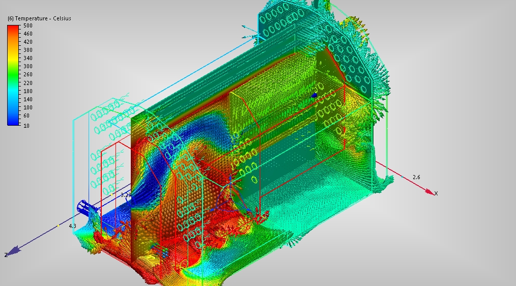
We find ourselves in such a window where the global tab shows the different characteristics of our entire detail.

The planes tab allows you to cut our part along any axis, as well as change the displayed result depending on the characteristics (temperature, pressure, flow rate) by clicking on the add button (big green plus), and for clarity, you can show the direction of movement with arrows flows in environments, in the vector tab, by selecting velocity vector and changing the size of the arrows in the edit / vector settings tab.


Also on the points tab, the add button adds a point anywhere in the model where you can measure all its parameters and add this point to the final report.

And for the sake of what the simulation is done, this is a report.
It can be found and saved in the summary file tab.
You can also show the movement of flows in schematic lines.

And for clarity, the full video of creating a simulation of this model: