FT232H, MPSSE and SPI programmer for 15 euros
It is strange that about this extremely popular and useful chip there has not yet been an article on Habré. I consider it necessary to fill this gap. The article will describe several interesting ways to use the FTDI FT232H chip and its analogues for various application purposes.
A few words about it: relatively cheap, easy to wiring and programming, a common USB 2.0 converter <-> serial protocols ( USART , SPI , I2C , JTAG TAP and just GPIO bit-bang), well suited for making your own devices with connection to PC via USB, and for testing and debugging other devices.
From a simple breakout-board on this chip, you can easily and naturally make a UART-converter, SPI-programmer, JTAG-debugger, I2C-master, GPIO bit-bang converter (and with it other protocols that do not require transcendent frequencies and are resistant to possible delays introduced by the USB stack, for example, Dallas 1-wire).
If the above features have managed to interest you - please, under cat.
A bit of history
Company FTDI was founded in 1992 in the city of Glasgow in Scotland. She specializes in USB-related solutions, and is known for its FT232 series USB-Serial converters, which have already been mentioned more than once on Habré in various articles on DIY hardware and microcontroller firmware. This series is still being successfully produced and sold, but progress does not stand still, and at the end of 2009, with the release of the FT2232D chip, the "reboot" of the series began, adding to the existing capabilities of the killer feature - the Multi-Protocol Synchronous Serial Engine ( MPSSE), which will be discussed in this article.MPSSE technology and its supporting chips
This technology provides hardware support for serial protocols SPI, I2C and JTAG, as well as the ability to "jump" GPIO after transferring the chip to a special mode, called, oddly enough, MPSSE Mode.This mode is currently supported by 4 different controllers manufactured by FTDI:
FT232H, FT2232D, FT2232H, FT4232H.
There are also various projects for emulating this mode on microcontrollers of various architectures and manufacturers, but in this article I will only consider FTDI, otherwise it risks growing even twice.
A good introduction to the technology, with wiring diagrams for each protocol, a list of supported features for each chip and explanations can be found in Application Note 135 with a telling nameMPSSE Basics .
Details about connecting and working with the relevant protocols are in separate ANs: SPI , I2C , JTAG .
Now a little from the technical specifications of the youngest of the 4 supported chips - FT232H , because the rest differ from it, by and large, only in the number of channels and the presence or absence of certain features (built-in LDO-controller, for example).
Let me quote some key TX from the datasheet :
- MPSSE Support
- USB <-> USART at speeds up to 12 MBaud (RS232 speed can be limited by an external logic level shift chip)
- Configurable GPIO pins with adjustable maximum current (4, 8, 12 or 16 mA)
- Storage of the pin configuration, operation mode after Reset, USB VID, DID and Description string in an external EEPROM with the possibility of overwriting it via USB
- Core voltage 1.8 V (incoming - from 3.3 V to 5 V), pins - 3.3 V (all pins are tolerant to 5 V)
- Temperature range -40 ° C to 85 ° C
- Available in LQFP48 and QFN packages
- Drivers available for Windows, MacOS X and Linux
I have nothing to add about USART here - this is the main mode of operation of all the chips in the series, and it works perfectly. All the necessary stop bit settings and hardware parity are supported, so you can safely make your own USB modem if necessary.
If the chip only needs a GPIO interface, then there are 16 pins per channel (in MPSSE mode), but if you plan to use GPIO in parallel with any of the hardware-supported protocols, only 12 pins will be available.
Configuration record (if any) external EEPROM) is performed by FT_Prog, there are few options available, the most important are Vendor ID, Device ID, Description and Serial Number.
The chip is unpretentious to power, it eats what they give (if they are given in the range indicated above), but its older brothers do not have an integrated LDO regulator, so you need to use an external one to power it from USB.
The LQFP48 case is quite solderable at home even in the absence of a hot air station or a soldering iron with a microwave tip, but everything, of course, depends on the hands. I will not talk about soldering QFN, if you can solder such cases, then you probably already heard about FT232 more than once.
About drivers, it is worth adding that FTDI provides two types of drivers on a royalty-free basis - Virtual Com. Port and D2XX Direct, but only the latter is needed to work with MPSSE. There is also a free libusb-based driver - libftdi .
I do not want to solder anything!
For those who do not want to solder, there are many breakout boards on the market equipped with an FT2232H chip (a dual-channel version of FT232H, which for simplicity can be considered two FT232H in one case), all the necessary binding and an external EEPROM.The board I bought cost 15 euros, in the CIS you can buy a similar one for about 600 rubles without delivery (from DiHalt , for example , just ask for an option for FT2232D, and it’s better to immediately for FT2232H, if any).
My board looks like this:
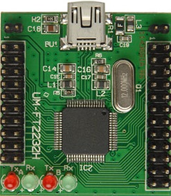
On the left - power, ground and 16 pins of channel A, on the right - power, ground, 16 pins of channel B, Reset and Wake-up. TX and RX diodes work correctly only in USART mode (unless you specifically ignite them programmatically when working with MPSSE), so I did not even solder them on my board. The LDO controller and the EEPROM chip are on the back of the board.
Practical use
Enough theory and stories, it's time to move on to practice. Imagine that you already have such a board, and now you are thinking about what you can do with it. And here's what:0 . USB <-> USART converter without any newfangled MPSSE there, as the fathers taught. There are a lot of applications for it, you can restore modems and routers killed by unsuccessful firmware, restore hard drives that are (slightly) damaged, connect to debug interfaces of various equipment, and so on, there are a lot of applications, I won’t consider them here.
1 . SPI programmerfor flashing and restoring BIOSes for more or less new PCs (produced in 2008 and newer, a mass transition to SPI-chips for storing BIOSs took place along with the introduction of X58, as I recall). With the introduction of SecureBoot technology (and its attendant ones), the firmware of a modified BIOS turned from an ordinary operation into a walk on a rake, as a result of which it would be possible to send a car to “brick” a machine. An external SPI programmer solves these problems completely.
2 . JTAG debugger for various MK. At the moment, I am flashing and debugging the following MKs with this board: STM32F1xx \ L1xx \ F4xx, Infineon XMC4500 (ARM Cortex-M) and Infineon XE167FM (C166), but the list of supported MKs is much wider, because such popular debuggers as open CooCox are based on FT232H Colinkand the closed but more powerful Amontec JTAGKey2 , under which you can successfully mimic.
3 . I2C bus master , which can be used, for example, to control the VID of a processor or video card, and under normal conditions, I2C is compatible with SMBus and PCBus, which hang half of the low-speed PC peripherals. So far I have not thoroughly studied this mode, so I will not describe working with it.
4 . USB <-> GPIO Converteron the basis of which it is possible to implement both simple tasks from the “turn off the device by pressing a button in the program” series and more complicated tasks, such as implementing your own protocols at the software level. At the same time, the program is written on a PC, which has both advantages (much more freedom in the choice of languages and an abundance of resources) and disadvantages (delays in the USB stack and its unpredictable timings will not allow implementing very high-speed protocols), but the very possibility not to use MK for interaction with iron for those who are unfamiliar with them is good.
I will dwell on paragraph 1, leaving paragraph 2 for the next article.
Making an SPI Programmer
To turn the FT232H-based board into an SPI programmer, we need:0. The board itself
1. An EEPROM chip with an SPI interface, for example, which is popular with manufacturers of modern motherboards Winbond W25Q64BV , which we will program. On desktop boards, they come in DIP8 (almost always) and SOIC8 (some Gigabyte and EVGA models), to simplify the replacement in case of BIOS damage, the chip is usually not soldered, but installed in a crib or ZIF socket. On laptops, the BIOS chip is most often soldered to the motherboard, and for programming you have to use an ISP port or a special clip, worn on top of the chip
2. Two optional 4.7 kΩ resistors for tightening the #WP and #HOLD pins to the power supply during firmware (you can do without them if the board has enough free 3.3 V pins)
3. Optional socket for the EEPROM chip (so as not to solder the wires to its conclusions)
4. PC with Linux (least of all gestures), Windows (more) or OS X (not officially supported, only by enthusiasts).
5. Installed in the utility system flashrom , collected from libftdi support.
Then everything is simple, we connect FT232H and EEPROM according to the scheme (taken from the scheme of my RushSPI programmer ):

Open the command line and run the command there:
flashrom -p ft2232_spi:type=232HFor multichannel FTDI chips, you will need to additionally indicate on which channel the connected EEPROM chip is located, for example, for FT2232H and channel A, the command will be like this:
flashrom -p ft2232_spi:type=2232H,port=AThe result of this command should be something like this:
Found chip "Winbond W25Q64.V" (8192 KB, SPI)If the chip was not found, then either you they messed up with the connection, either your flashrom was built without libftdi, or you have Windows and you need to install another driver based on the manufacturer found on the system from the manufacturer libusb, as described here .
If the chip is found, then now read the contents with the same command with the additional key -r dumpname.rom, or write your file with the command with the -w newbios.rom switch. A
list of available keys supported by programmers and everything else can be found inofficial wiki project . There is also an article on FT232H-based programmers, here it is .
Conclusion
The resulting programmer flashes the eight-megabyte SPI chip in ~ 150 seconds, which is not fast, but not too long, and for 15 euros - just fine.With its help, I have repeatedly restored my BIOS, which could not stand the experiments .
With his help (though in USART converter mode), it was possible to fix a broken hard drive.
About firmware and debugging of various MK on JTAG with its help I will tell in the next article.
Please report any possible errors, errors and flaws in L \ C.
Thank you for reading and for reading this footcloth.