We apply Voronoi mosaic, pixelation and geometric masks in shaders to decorate the site
- Tutorial
This article is a logical continuation of the introduction to programming shaders for web designers . In it, we made a template for creating various 2D effects with photos using shaders and looked at a couple of examples. In this article we will add a couple of textures, apply Voronoi splitting to create a mosaic of them, talk about creating different masks in shaders, pixelation, and also touch on some of the problems of the ancient GLSL syntax that still exists in our browsers.
Just as last time, there will be a minimum of theory and a maximum of practice and reasoning in a mundane everyday language. Beginners will find here a sequence of actions with tips and useful comments, and experienced front-tenders will probably find a couple of ideas for inspiration.
A survey in a previous article showed that the theme of WebGL effects for sites may be of interest not only to the layout designers, but also to our colleagues of other specializations. In order not to be puzzled by the latest ES chips, we intentionally confine ourselves to more traditional syntactic constructions that everyone can understand. And again I draw the attention of readers to the fact that the built-in editors from CodePen affect the performance of what is being done in them.
But let's start ...
Template for working with shaders
For those who have not read the previous article - we have made the following template for working with shaders:
It creates a plane (in our case, a square) on which the picture-texture is drawn. No extra dependencies and a very simple vertex shader. Then we developed this pattern, but now we will start from the moment when there is no logic in the fragment shader yet.
Mosaic
Mosaic is a plane broken into small areas, where each of the areas is filled with a certain color or, as in our case, a texture. How can we even break our plane into pieces? Obviously, you can break it into rectangles. But this is so easy to do with the help of SVG, to drag WebGL into this task and lay everything out of the blue to absolutely nothing.
For a mosaic to be interesting, there must be different fragments in it, both in shape and in size. There is one very simple, but at the same time very entertaining approach to building such a partition. It is known as the Voronoi mosaic or the Dirichlet partition, and they write on Wikipedia that Descartes used something similar back in the 17th century. The idea is something like this:
- Take a set of points on the plane.
- For each point on the plane, find the point closest to it from this set.
- Actually that's all. The plane is divided into polygonal regions, each of which is defined by one of the points of the set.
Probably better to show this process with a practical example. There are different algorithms for generating this partition, but we will act on the forehead, because calculating something for each point on the plane is just the task for the shader. First we need to make a set of random points. In order not to load the code of the examples we will make a global variable for them.
functioncreatePoints() {for (let i = 0; i < NUMBER_OF_POINTS; i++) {
        POINTS.push([Math.random(), Math.random()]);
    }
}
Now we need to transfer them to the shaders. The data is global, so we will use the modifier uniform. But there is one subtle point: we simply cannot pass on an array. It would seem that the 21st century is in the courtyard, but still nothing will come of it. As a result, you have to transfer an array of points one by one.
for (let i = 0; i < NUMBER_OF_POINTS; i++) {
    GL.uniform2fv(GL.getUniformLocation(PROGRAM, 'u_points[' + i + ']'), POINTS[i]);
}
Today, we will repeatedly encounter similar problems of inconsistency between what is expected and what is in real browsers. Typically, WebGL lessons use THREE.js and this library hides some of the dirt in itself, as jQuery once did in its tasks, but if you remove it, the reality hurts your brain.
In the fragment shader, we have an array variable for points. We can create only fixed-length arrays. Let it start with 10 points:
#define NUMBER_OF_POINTS 10
uniform vec2 u_points[NUMBER_OF_POINTS];
Make sure of the performance of all this by drawing circles on the ground points. Such drawing of various geometric primitives is often used for debugging - they can be clearly seen and you can immediately understand what is and where it is going.
Use the "drawing" circles, direct and other landmarks for invisible objects on which animations are built. This will give obvious clues about how they work, especially if the algorithms are difficult to quickly understand without prior preparation. Then all this can be commented out and left for colleagues - they will say thank you.
for (int i = 0; i < NUMBER_OF_POINTS; i++) {
    if (distance(texture_coord, u_points[i]) < 0.02) {
        gl_FragColor = WHITE;
        break;
    }
}
Good. Let's also add a little movement to the points. Let them move in a circle to begin with, we will return to this issue later. The coefficients are also set by the eye, just to slow down their movement slightly and reduce the amplitude of oscillations.
functionmovePoints(timeStamp) {if (timeStamp) {
        for (let i = 0; i < NUMBER_OF_POINTS; i++) {
            POINTS[i][0] += Math.sin(i * timeStamp / 5000.0) / 500.0;
            POINTS[i][1] += Math.cos(i * timeStamp / 5000.0) / 500.0;
        }
    }
}
We return to the shader. For future experiments, the numbers of the regions into which everything is divided will be useful. So we find the point from the set closest to the current pixel and save the number of this point - the same as the area number.
float min_distance = 1.0;
int area_index = 0;
for (int i = 0; i < NUMBER_OF_POINTS; i++) {
    float current_distance = distance(texture_coord, u_points[i]);
    if (current_distance < min_distance) {
        min_distance = current_distance;
        area_index = i;
    }
}
To test the performance again, let's paint everything in bright colors:
gl_FragColor = texture2D(u_texture, texture_coord);
gl_FragColor.g = abs(sin(float(area_index)));
gl_FragColor.b = abs(sin(float(area_index)));
The combination of the module (abs) and limited functions (in particular, sin and cos) is often used when working with similar effects. On the one hand, this adds a bit of randomness, but on the other hand, it immediately gives a normalized result from 0 to 1, which is very convenient - we will have very many values within these limits.
We also find points that are more or less equidistant from several points in the set, and paint them. This action does not carry much payload, but it's still interesting to look at the result.
int number_of_near_points = 0;
for (int i = 0; i < NUMBER_OF_POINTS; i++) {
    if (distance(texture_coord, u_points[i]) < min_distance + EPSILON) {
        number_of_near_points++;
    }
}
if (number_of_near_points > 1) {
    gl_FragColor.rgb = vec3(1.0);
}
It should turn out something like this:
This is still a draft version, we will continue to refine it. But now the general concept of such a separation of the plane is clear.
Mosaic of photos
It is clear that in the pure form of the benefits of such a partition is not very much. To expand the horizons and just for the sake of interest, you can play with it, but on a real site it would be worth adding a couple more photos and making a mosaic of them. Let's alter the texture creation function a little to make it more than one.
functioncreateTextures() {
    for (let i = 0; i < URLS.textures.length; i++) {
        createTexture(i);
    }
}
functioncreateTexture(index) {
    const image = new Image();
    image.crossOrigin = 'anonymous';
    image.onload = () => {
        const texture = GL.createTexture();
        GL.activeTexture(GL['TEXTURE' + index]);
        GL.bindTexture(GL.TEXTURE_2D, texture);
        GL.pixelStorei(GL.UNPACK_FLIP_Y_WEBGL, true);
        GL.texImage2D(GL.TEXTURE_2D, 0, GL.RGB, GL.RGB, GL.UNSIGNED_BYTE, image);
        GL.texParameteri(GL.TEXTURE_2D, GL.TEXTURE_WRAP_S, GL.CLAMP_TO_EDGE);
        GL.texParameteri(GL.TEXTURE_2D, GL.TEXTURE_WRAP_T, GL.CLAMP_TO_EDGE);
        GL.texParameteri(GL.TEXTURE_2D, GL.TEXTURE_MIN_FILTER, GL.LINEAR);
        GL.uniform1i(GL.getUniformLocation(PROGRAM, 'u_textures[' + index + ']'), index);
    };
    image.src = URLS.textures[index];
}
Nothing unusual happened, we just replaced the zeros with the parameter indexand reused the already existing code to load three textures. In the shader, we now have an array of textures:
#define NUMBER_OF_TEXTURES 3
uniform sampler2D u_textures[NUMBER_OF_TEXTURES];
Now we can use the region number saved earlier to select one of the three textures. But...
But before that I would like to make a small digression. About sore. About syntax. Modern Javascript (conditionally ES6 +) is a nice language. It allows you to express your thoughts as they arise, does not limit the scope of a particular programming paradigm, completes some points for us and allows us to focus more on the idea than on its implementation. For the creator - the most it. Some people think that it gives too much freedom and switch to TypeScript for example. Pure C is a stricter language. He also allows a lot, you can find anything on him, but after JS he is perceived as a little awkward, old-fashioned or something. Nevertheless, he is still good. GLSL as it exists in browsers is just something. Not only is he an order of magnitude stricter than C, since it still lacks many familiar operators and syntactic constructs. This is probably the biggest problem when writing more or less complex shaders for WebGL. Behind the horror that the code turns into, it can be very difficult to look at the original algorithm. Some layout designers think that until they have learned C, the path to shaders is closed for them. So: knowledge of C here does not help. Here is a world of its own. The world of madness, dinosaurs and crutches.
How can I choose one of three textures with one number - the area number. The remainder of dividing the number by the number of textures comes to mind. Great idea. Only the operator %, who already writes the hands, is not here. The impression of understanding this fact is well described by the picture:

Of course you will say "yes, not a problem, there is a function mod- we will take it!". But it turns out that it does not accept two integers, only fractional ones. Ok, well, make of them float. We floatget the same , but we need int. You have to convert everything back, otherwise there is a non-illusory chance to get an error when compiling.
int texture_index = int(mod(float(area_index), float(NUMBER_OF_TEXTURES)));And here's a rhetorical question: maybe it would be easier to implement its remainder function from dividing integers, rather than trying to assemble it from standard methods? And this is still a simple function, and it happens that very deeply nested sequences of such transformations are obtained, in which it is not quite clear what is happening.
Okay, let's leave it as it is. Just take the color of the desired pixel from the selected texture and assign it to a variable gl_FragColor. So? We have already done this? And then this cat appears again. You cannot use a non-constant when referring to an array. And all that we have calculated is no longer a constant. Ba-dum-tsss !!!
You have to do something like this:
if (texture_index == 0) {
    gl_FragColor = texture2D(u_textures[0], texture_coord);
} else if (texture_index == 1) {
    gl_FragColor = texture2D(u_textures[1], texture_coord);
} else if (texture_index == 2) {
    gl_FragColor = texture2D(u_textures[2], texture_coord);
}
Agree, this code direct road to govnokod.ru , but nevertheless in a different way. Even the operator switch-caseis not here to somehow improve this disgrace. There is a truth yet another, less obvious crutch, solving the same task:
for (int i = 0; i < 3; i++) {
    if (texture_index == i) {
        gl_FragColor = texture2D(u_textures[i], texture_coord);
    }
}
Cycle counters that increment by one can be considered by the compiler to be constant. But with an array of textures, this could not be done - in the last Chrome there was an error saying that it is impossible to do this with an array of textures. With an array of numbers worked. Guess why it works with one array, but not with the other? If you thought that the type conversion system in JS is full of magic - sort out the "constant - not constant" system in GLSL. The funniest thing here is that the results also depend on the video card used, so that the tricky crutches that worked on the NVIDIA video card may well break on AMD.
It is better to avoid such decisions based on assumptions about the operation of the compiler. They tend to break down and are difficult to test.
Sadness, sadness. But if we want to do interesting things, we need to abstract from all this and continue.
At the moment we got a mosaic of photos. But there is one detail: if the points are very close to each other, then there is a rapid transition of two areas. It is not very beautiful. We need to add some algorithm that does not allow the points to come closer. You can make a simple option, which checks the distance between points and, if it is less than a certain value, then we push them apart. This option is not without flaws, in particular, it sometimes leads to a slight twitching of points, but in many cases it can be enough, especially since the calculations here are not very much. More advanced variants would be a system of moving charges and a “web”, in which pairs of points are connected by invisible springs. If you are interested in implementing them,
for (let i = 0; i < NUMBER_OF_POINTS; i++) {
    for (let j = i; j < NUMBER_OF_POINTS; j++) {
        let deltaX = POINTS[i][0] - POINTS[j][0];
        let deltaY = POINTS[i][1] - POINTS[j][1];
        let distance = Math.sqrt(deltaX * deltaX + deltaY * deltaY);
        if (distance < 0.1) {
            POINTS[i][0] += 0.001 * Math.sign(deltaX);
            POINTS[i][1] += 0.001 * Math.sign(deltaY);
            POINTS[j][0] -= 0.001 * Math.sign(deltaX);
            POINTS[j][1] -= 0.001 * Math.sign(deltaY);
        }
    }
}
The main problem of this approach, as well as the one we used in the shader, is a comparison of all points with all. You do not need to be a great mathematician to understand that the number of distance calculations will be incredible if we make not 10 points, but 1000. Yes, even 100 is enough for everything to slow down. Therefore, it makes sense to apply it only for a small number of points.
If we want to make such a mosaic for a large number of points, then we can use the already familiar to us division of the plane into equal squares. The idea is to place a single point in each square, and then carry out all comparisons only with points from adjacent squares. The idea is good, but experiments have shown that, with a large number of points, inexpensive laptops with integrated video cards still fail. Therefore, it is worth thinking ten times before deciding to make such a mosaic of a large number of fragments on your website.
Do not be radishes, check the speed of their crafts, not only on your mining farm, but also on ordinary laptops. Most users will have them.
Splitting a plane into parts according to a function graph
Let's look at another option of dividing the plane into parts. He will not require large computing power. The basic idea is to take some mathematical function and plot it. The resulting line will divide the plane into two parts. If we use a view function y = f(x), we get a division in the form of a cut. Replacing X with Y, we can change the horizontal section to the vertical one. If we take the function in polar coordinates, then it will be necessary to convert everything to Cartesian and vice versa, but the essence of the calculations will not change. In this case, it will not be a cut into two parts, but rather a hole cutting. But we will see the first option.
For each Y, we will calculate the value of X to make a vertical cut. We could take for this purpose a sine wave for example, but this is too boring. It is better to take them at once a few pieces and lay down.
We take several sinusoids, each of which is tied to the Y coordinate and time, and we add them. Physicists would call such an addition a superposition. Obviously, by multiplying the whole result by some number, we change the amplitude. We take it out to a separate macro. If you multiply the coordinate - the sine parameter, the frequency will change. We have already seen this in the last article. We also remove from the formula the frequency modifier common to all sinusoids. It will not be superfluous to play with time, a negative sign will give the effect of moving the line in the opposite direction.
floattime = u_time * SPEED;
float x = (sin(texture_coord.y * FREQUENCY)
    + sin(texture_coord.y * FREQUENCY * 2.1    + time)
    + sin(texture_coord.y * FREQUENCY * 1.72   + time * 1.121)
    + sin(texture_coord.y * FREQUENCY * 2.221  + time * 0.437)
    + sin(texture_coord.y * FREQUENCY * 3.1122 + time * 4.269))
        * AMPLITUDE;
Having made such global settings for our function, we will face the problem of repeating the same movement at rather short intervals. In order to solve this question, we need to multiply everything by the coefficients, which have the smallest common multiple and a very large one. Something similar is used in the random number generator, remember? In this case, we did not think and took ready numbers from some example from the Internet, but no one bothers to experiment with their values.
It remains only to choose one of two textures for points above our graph of the function and the second for points below it. More precisely, to the left and to the right, we all turned:
if (texture_coord.x - 0.5 > x) {
    gl_FragColor = texture2D(u_textures[0], texture_coord);
} else {
    gl_FragColor = texture2D(u_textures[1], texture_coord);
}
What we received is reminiscent of sound waves. More precisely, their image on the oscilloscope. And indeed, instead of our sine waves, we could transfer data from some sound file. But working with sound is a topic for a separate article.
Masks
The previous examples should push on quite a logical remark: it all looks like the work of masks in SVG (if you didn’t work with them - see examples from the SVG mask article and wow effects ). Just here we do them a little differently. As a result, the same is obtained - some areas are painted with one texture, some with another. Only smooth transitions have not yet been. So let's do one.
We remove all unnecessary and return the coordinates of the mouse. Make a radial gradient with the center at the cursor location and use it as a mask. In this example, the behavior of the shader will more closely resemble the logic of the masks in the SVG than in the previous examples. We will need a function mixand some function of distance. The first will mix the pixel color values from both textures, taking as a third parameter a coefficient (from 0 to 1), which determines which of the values will prevail in the result. As a function of distance we take the sine modulus - it will just give a smooth change in the value between 0 and 1.
gl_FragColor = mix(
    texture2D(u_textures[0], texture_coord),
    texture2D(u_textures[1], texture_coord),
    abs(sin(length(texture_coord - u_mouse_position / u_canvas_size))));
Actually that's all. Look at the result:
The main advantage over SVG is obvious:
In contrast to the SVG, here we can easily make smooth gradients for various mathematical functions, and not to collect them from a variety of linear gradients.
If you have a simpler task that does not require such smooth transitions or complex shapes that are calculated in the process, then most likely it will be easier to implement without using shaders. And the performance on a weak gland is likely to be better. Choose a tool based on your tasks.
For educational purposes, let's look at another example. To begin with, we make a circle in which the texture will remain as it is:
gl_FragColor = texture2D(u_textures[0], texture_coord);
float dist = distance(texture_coord, u_mouse_position / u_canvas_size);
if (dist < 0.3) {
    return;
}
And all the rest is filled with diagonal stripes:
floatvalue = sin((texture_coord.y - texture_coord.x) * 200.0);
if (value > 0.0) {
    gl_FragColor.rgb *= dist;
} else {
    gl_FragColor.rgb *= dist / 10.0;
}
All the same, we multiply the parameter for the sine to increase the frequency of the strips; we divide the obtained values into two parts; for each of the halves we convert the color of the pixels in our own way. It is useful to remember that drawing diagonal lines is usually associated with the addition of coordinates along X and Y. Please note that we all also use the distance to the mouse cursor when colors change, thereby creating a kind of shadow. In the same way you can use it in geometric transformations, we will soon look at the example of pixelation. In the meantime, take a look at the result of this shader:
Simple and cute.
And yes, if you get a little confused, you can make textures not from images, but from frames from video (there are many examples in the network, you can easily figure them out), and apply all our effects to them. Many sites from directories like Awwwards use similar effects in combination with video.
One more thought to remember:
No one bothers to use one of the textures as a mask. We can take a picture and use the color values of its pixels in our transformations, be it changes of other colors, shifts to the sides or something else that comes to your mind.
But back to breaking the plane into parts.
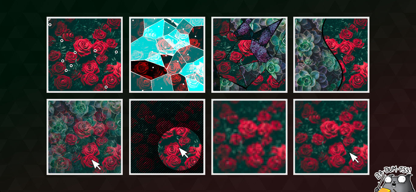
Pixelate
This effect is somewhat obvious, but at the same time it is so common that it would be wrong to pass by. We divide our plane into squares in the same way as in the example with the noise generator, and then set the same color for all pixels inside each square. It is obtained by mixing the values from the corners of the square; we have already done something similar. For this effect, we do not need complex formulas, so we simply add all the values and divide by 4 - the number of corners of the square.
float block_size = abs(sin(u_time)) / 20.0;
vec2 block_position = floor(texture_coord / block_size) * block_size;
gl_FragColor = (
    texture2D(u_textures[0], block_position)
        + texture2D(u_textures[0], block_position + vec2(1.0, 0.0) * block_size)
        + texture2D(u_textures[0], block_position + vec2(0.0, 1.0) * block_size)
        + texture2D(u_textures[0], block_position + vec2(1.0, 1.0) * block_size)
    ) / 4.0;
Again, we tied one of the parameters to time through the sine module in order to visually see what happens when it changes.
Pixel waves
Finally, we once again apply the techniques already known to us in one place to add waves to the example with pixels.
float block_size = abs(sin(
    length(texture_coord - u_mouse_position / u_canvas_size)
        * 2.0 - u_time)) / 100.0 + 0.001;
Use the sine module to drive everything from 0 to 1; add the distance from the current position to the mouse cursor, time, and select some coefficients to make it all look beautiful. To the result we add a small constant in order to avoid zero block sizes.
These are rather peculiar "pixel" waves, but just as one could take the shifts from the previous article and calculate them, not the size of pixel blocks. Then more natural waves will turn out. Also, no one bothers to make several "points of excitement", the waves of which will be mixed, as we mixed the sines in one of the previous examples. The scope for fantasy is wide enough. The only thing to remember is performance. Do not abuse with a lot of calculations.
Results
Taking the pattern from the introduction to the programming of shaders, we implemented several popular effects, looked at the ideas that were put into them, repeated a couple of times and added them to our collection of knowledge. Further study of shaders in the context of two-dimensional effects will be reduced to all sorts of experiments and the realization of their fantasies or the ideas of our fellow designers. It is already difficult to systematize such things and present them in the form of a sequence of more or less related examples. Therefore, we will stop at this point with the analysis of two-dimensional effects. Novice developers would like to wish patience in studying this topic. This is one of the areas in which there are no proven paths of development, so you have to experiment a lot to start doing such things freely.
PS: What topics related to WebGL (or with the development of non-standard sites in general) in your opinion should be covered in articles on Habré? This area is quite wide and, as I understand it, not very systematized. What topics should pay attention in the first place?